A few months ago, for fun I bought a crumby hobby grade CNC router from one of my favorite low cost online suppliers. I was working with some development 3D printed skate trucks and I needed to cut some wheel wells in a skate deck in a more precise way than I had in the past. With the insanely low cost of these machines, I had little to lose even if it just turned into spare parts.
Vevor CNC 3018 DIY 3 Axis Engraver Kit GRBL Control $149.99 with free shipping (now $154.99). This is the same 3018 sold all over by Cronos.
It went terribly. The near total lack of rigidity meant that cutting mere plywood took forever and pushed the machine to it’s limits. The spindle just flaps around and gets really scary if pushed hard.
I need to have a CNC router available to me for some upcoming carbon and wood skate deck projects as well as for cutting molds for bike projects. I decided to make something nice.
Contrary to what most do, make the router then the control box, I decided to do things the opposite way. Electricity and electronics are my worst skills and I have a lot to learn. It also seemed to me that most designs for home made CNC routers are limited primarily by the control systems and if left for the end, there is a lot missing in the final product.
I have several goals with this project.
- I need a real CNC router.
- I need to learn how to do the work of engineering and assembly of these systems well for professional and vocational reasons.
- I want a stand alone system that isn’t dependent on connections to outside computers.
- I also wanted a control box that would allow me to modularly work with the offline controller as well as GRBL, Arduino, Raspberry Pi, Pico, as well as other control systems.
The last point is important. In a way, I’m not building one control box. I’m building five at once. Having a modular architecture and a power and motion control in place ready to plug into, many interesting electronics projects can be worked on by myself or students without the very heavy backend requirements to truly test ideas.
Thus, to start the box, I’m going to do the quick exercise of hacking the Cronos GRBL control board into a proper CNC control box format. If I make any tragic mistakes, I can recover as this is a very cheap platform. I really am a noob with this type of project so I could really screw up. These boards are commonly available in the marketplace for $39.99 and are an easy choice for a student looking to get into this type of project. It will also control a laser but I’m going to deal with all that at another time.
This isn’t a serious upgrade in a way that will show up at the machine. Functionally, other than the spindle upgrade, it’s basically the same. Instead, it’s the ground work to bring the system to another level. Getting a control that is configurable within a more professional box. While some of the costs laid out here may seem expensive at first glance, remember, these are professional quality components, with data sheets (generally), that can be used again in later iterations of design or other projects.
I am making every effort to keep the parts as compact as practical. Effort on this now will make many decisions far easier later in the project.
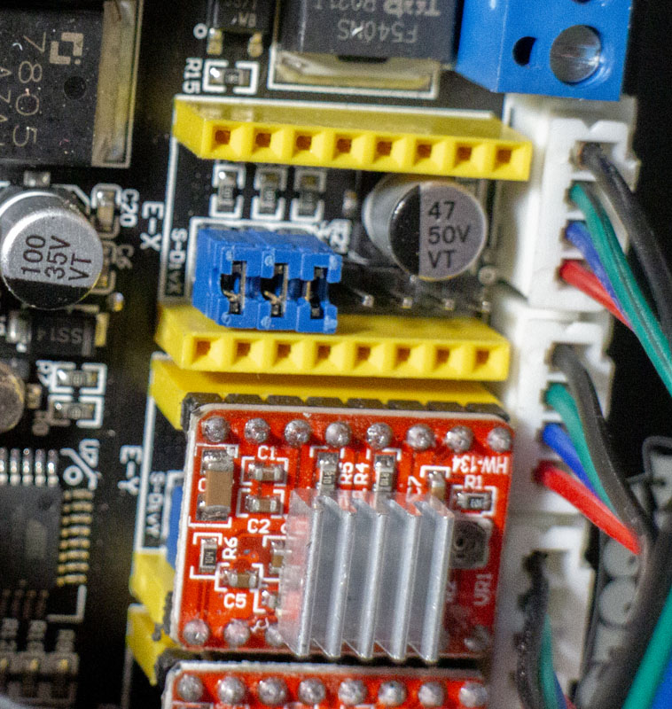
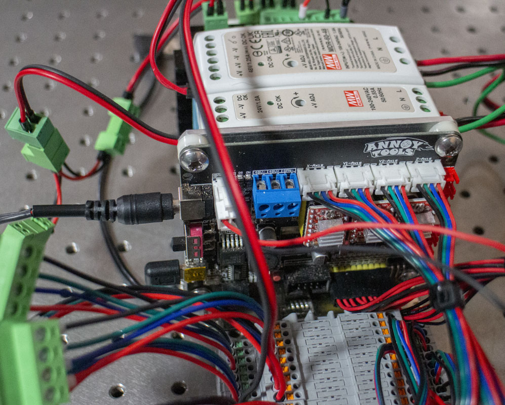
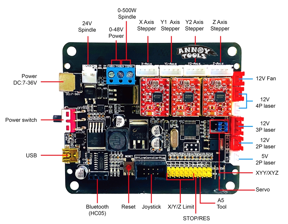
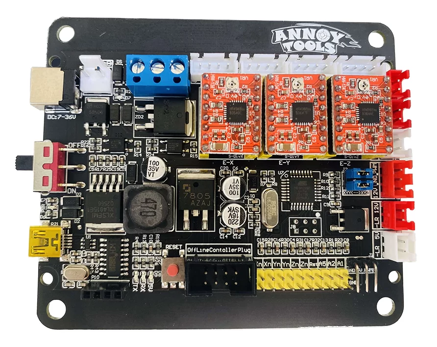
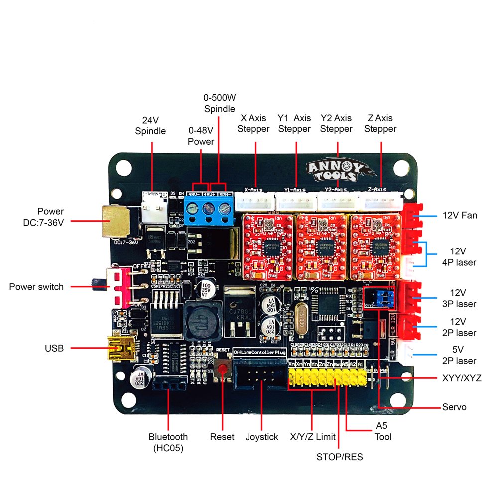
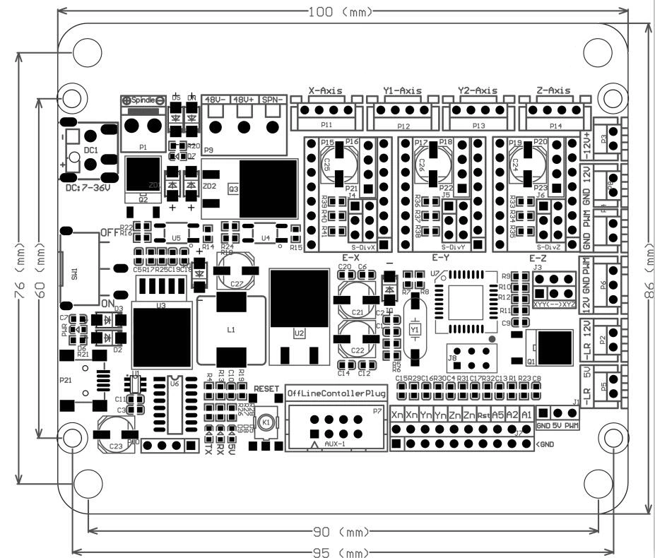
The board is a Cronos Maker GRBL1.1 TMC2208 board. It is GRBL based and commonly uses CANDLE as an interface. These are open source codes and available to anyone. The board can be flashed with updated code much line any Arduino, see HERE.
It’s popular to build a controller box like I’m doing here using Newfangled Solutions Mach 3 and a suitable board. The cost of that software is $175 and boards are $30 – $200. The architecture is a bit better when using these boards but with the cost, I’d prefer investing in a true offline controller. For example, a DDCS NCH-02. This is a quality offline control for $200.
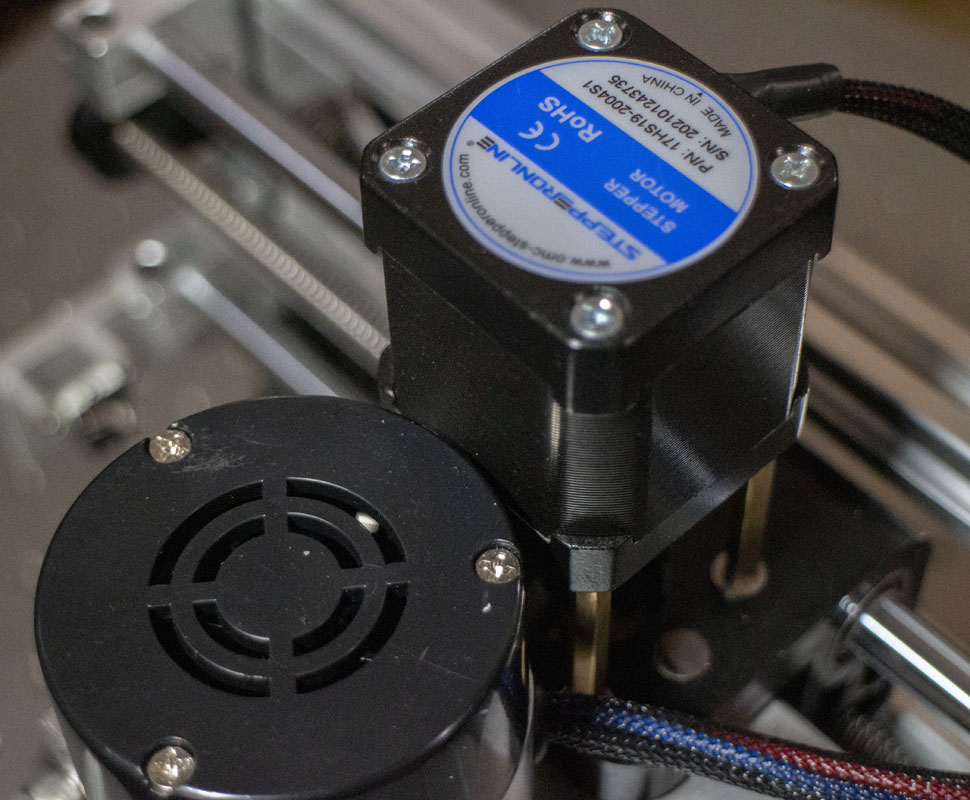
First, DC1 pin on the board gets 24v power from the a power supply on the DIN35 rail. This will run the board and the three small NEMA 17 (42×42 x,y 33mm 1.33A, z 47mm 2A) stepper motors.
In testing while rapid feeding all axii at the same time, no load, and the draw was close to 0.50 amps which means that a 1.00 amp power supply is probably perfect. I’ll keep my eye on this and see what happens under load as amperage will go up.
MEAN WELL MDR-20-24 AC to DC DIN-Rail Power Supply 24V 1.00 Amp,24W $18.85

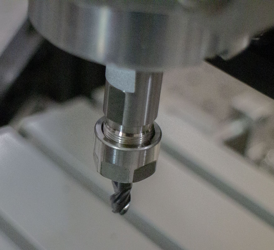
Obviously, everyone is going to first upgrade the spindle. The stock unit is just a toy, doesn’t spin very fast, and isn’t rigid at all. You’d be mistaken to think that you’re going to fix the rigidity issue with a spindle swap alone. Still, it’s a worthy upgrade if you aren’t going to do much else.
Daedalus CNC Brushless Spindle Motor, 400w, ER11, 48V DC, 12000RPM $69.99
Daedalus 55mm Spindle Clamp Mounting Bracket (55MM Clamp) $13.99
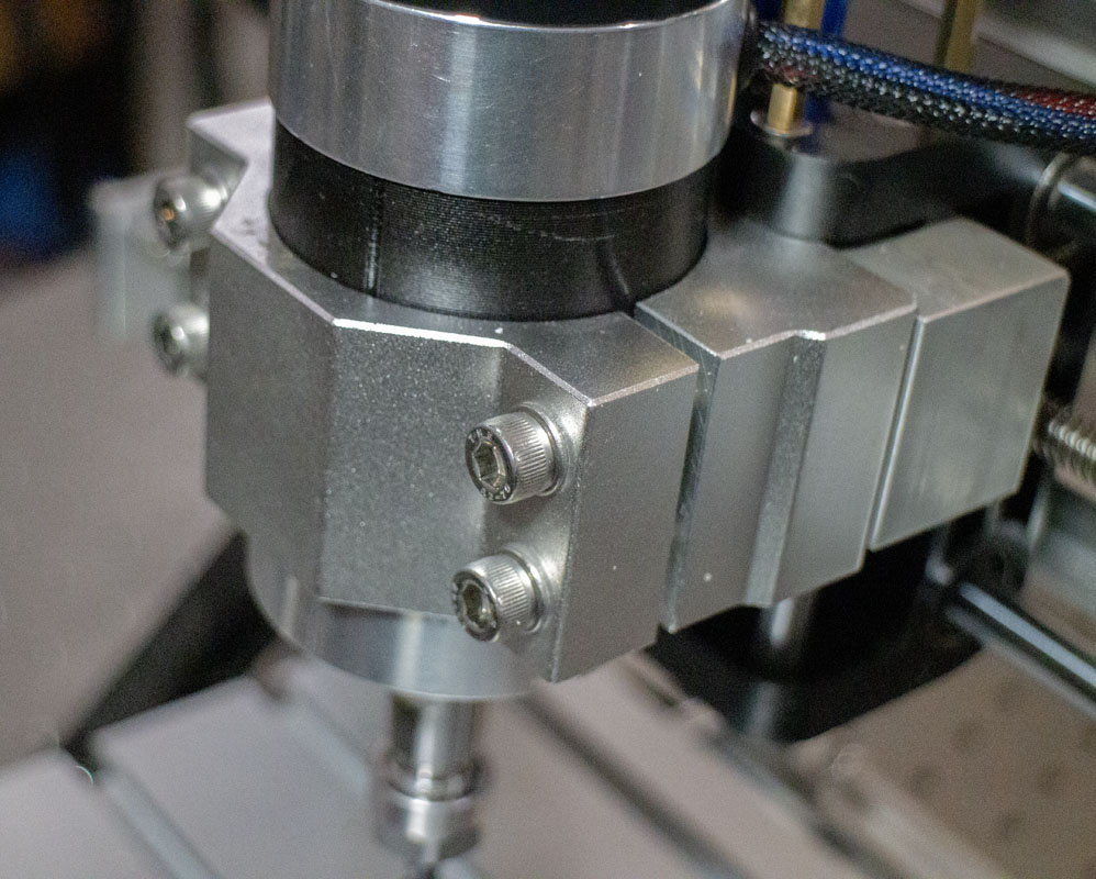
This motor was chosen for some very specific reasons. While it is still small enough to work with the 3018 system, it has the tool collet taper actually built into the motor’s spindle. Many small CNC spindle motors still require funky and flexible adapters to simple small motor shafts. I could also use this in a proper machine later if needed. This was a good compromise for the short term.
First spindle issue, you need to power this separately than the GRBL board. It’s 48V and requires over 1 Amp service. That means we need a power supply and a driver.
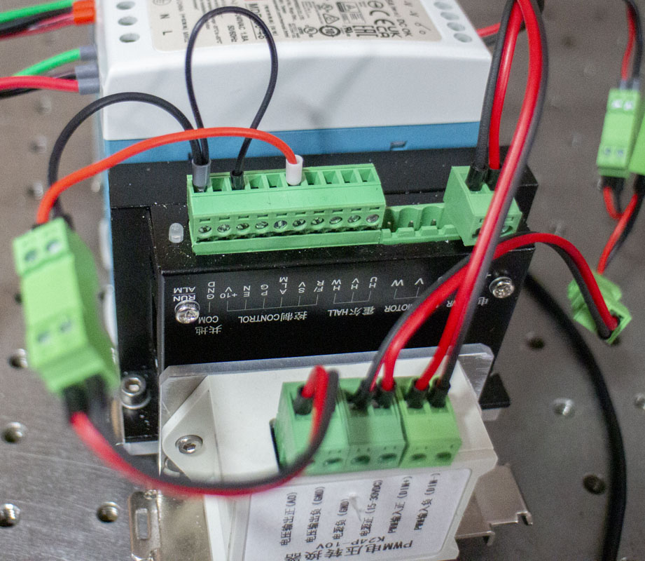
WS55-220, 3 Phase BLDC Motor Controller $42.59
MEAN WELL MDR-60-48 AC to DC DIN-Rail Power Supply 48V 1.25 Amp 60W $20.50
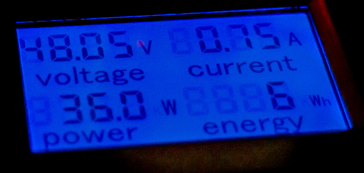
I am still working on sizing this power supply. Typically these spindles are sold with 10amp power supplies. With the motor spinning at 12,000 without any load, the driver is pulling just shy of 0.90 amp. I will have more to add here later as I start pushing the motor hard. By grabbing the spindle to load it at lower speeds, the draw goes up to about 4.5 amps so the end may be a Delta CliQ II Series DRP048V480W1BA 480W power supply that I have on hand. It’s a nice compact high output power supply. I’ll plan on using it and see what happens with the consumption as this unit should we well in the range.
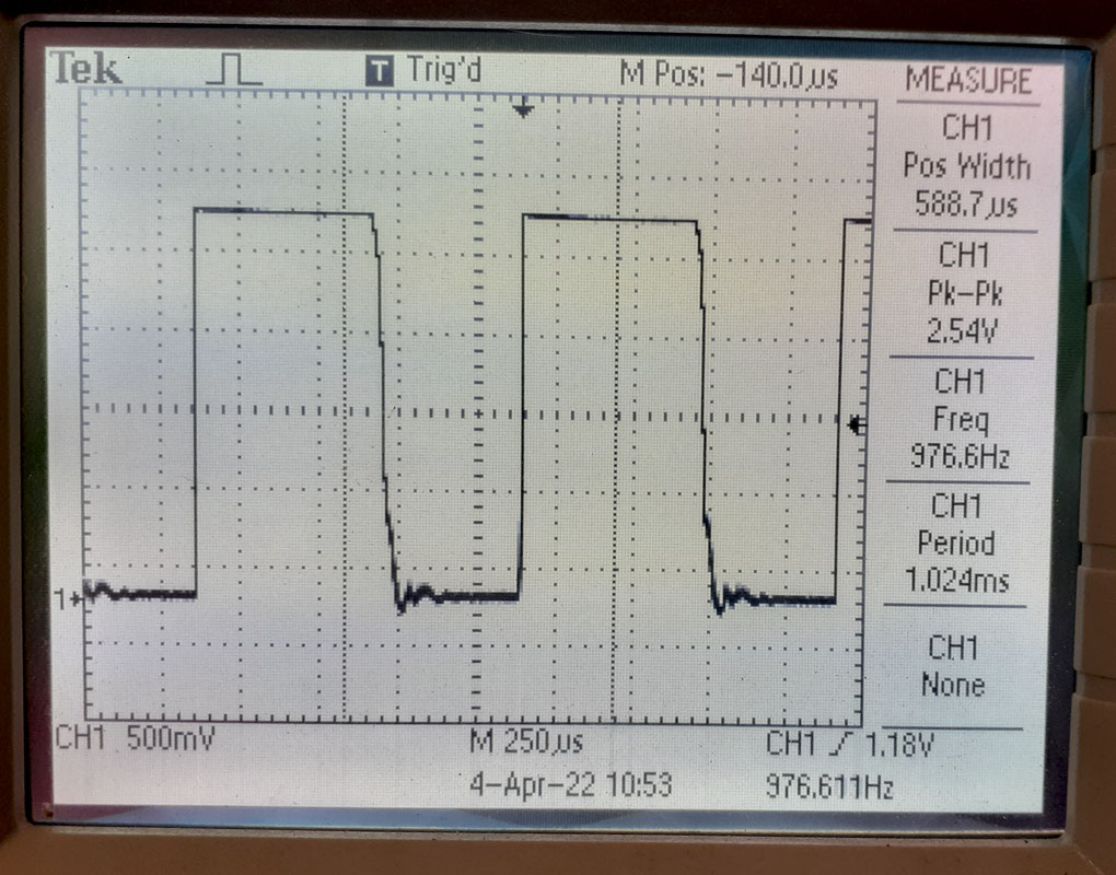
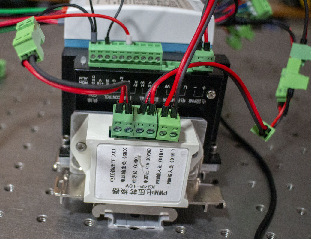
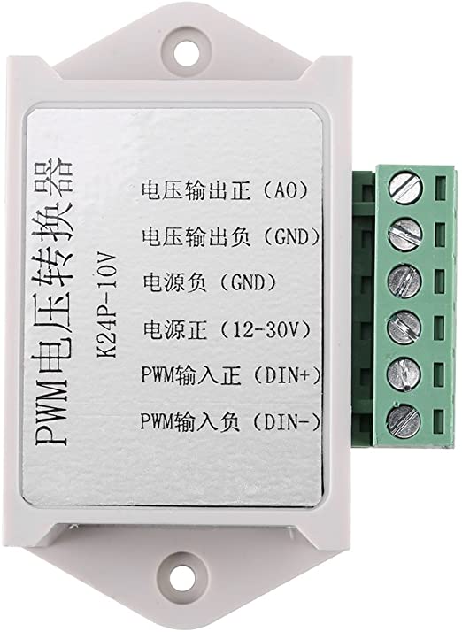
Now you have the next issue, the P1 spindle output on the Annoy board is a 24v PWM digital 8-bit signal. The WS55-220 controller is looking for a 0-10v analog signal to determine spindle speed. Many people online just give up and go to a separate manual control for spindle speed but we aren’t going to do that here as it would defeat the whole point of using a program. This is what works.
Hilitand 24V PWM to 0-10V Converter $17.78
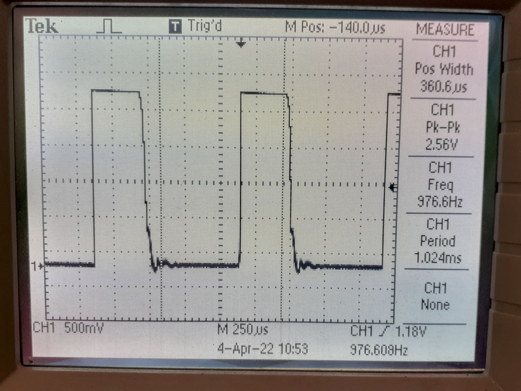
The PWM unit here actually does exactly what you intend it to do. Also, as it has Phoenix Contact 3.81mm printed-circuit board connectors (MC 1,5/ 2-ST-3,81 – 1803578) in the design means that it’s ready for a modular install. I tried several other cheaper and similarly priced units prior to this. They didn’t or barely worked. Don’t fuck around, get this one.
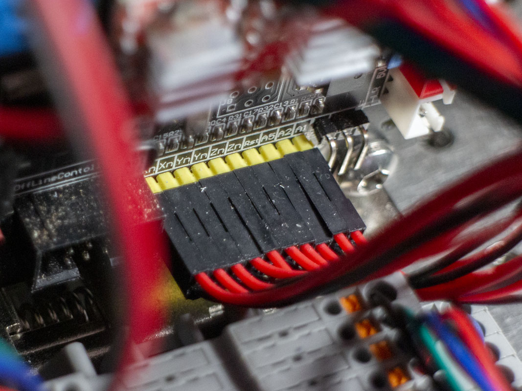
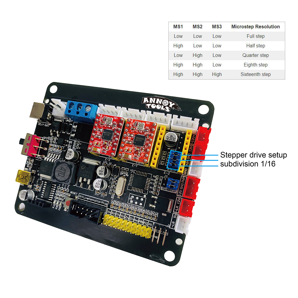
We can also change the micro step resolution of the little TMC2208 stepper motor drivers. There are jumpers hidden beneath the driver boards on the Annoy card. A range of full step to sixteenth step is provided.
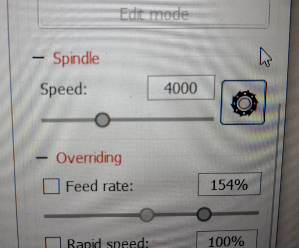
This change of the spindle and control will require a setting change in Candle software, here $30 is set to 17720. As the digital signal is 8-bit, you will really only see 256 increments. Make sure to set the minimum spindle speed to 0 and max to 12000. You won’t be able to get very low, I’m only able to free spin at about 500rpm. The thing is that without a 0-12000 setting, the tune will be impossible to be even approximate to the program.
This will change our setup in the Candle program. An easy to use cheat sheet for understanding these settings is available HERE.
| $0=10 | $20=0 | $100=800.000 | ||
| $1=100 | $21=0 | $101=800.000 | ||
| $2=0 | $22=1 | $102=800.000 | ||
| $3=1 | $23=0 | $110=1450.000 | ||
| $4=0 | $24=100.000 | $111=1450.000 | ||
| $5=0 | $25=1000.000 | $112=1450.000 | ||
| $6=0 | $26=250 | $120=3000.000 | ||
| $10=1 | $27=1.000 | $121=3000.000 | ||
| $11=0.010 | $30=17720 | $122=3000.000 | ||
| $12=0.020 | $31=0 | $130=299.000 | ||
| $13=0 | $32=0 | $131=179.000 | ||
| $132=44.000 | ||||

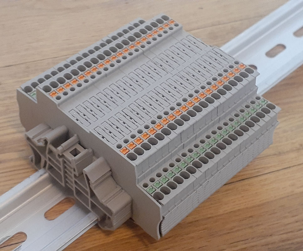
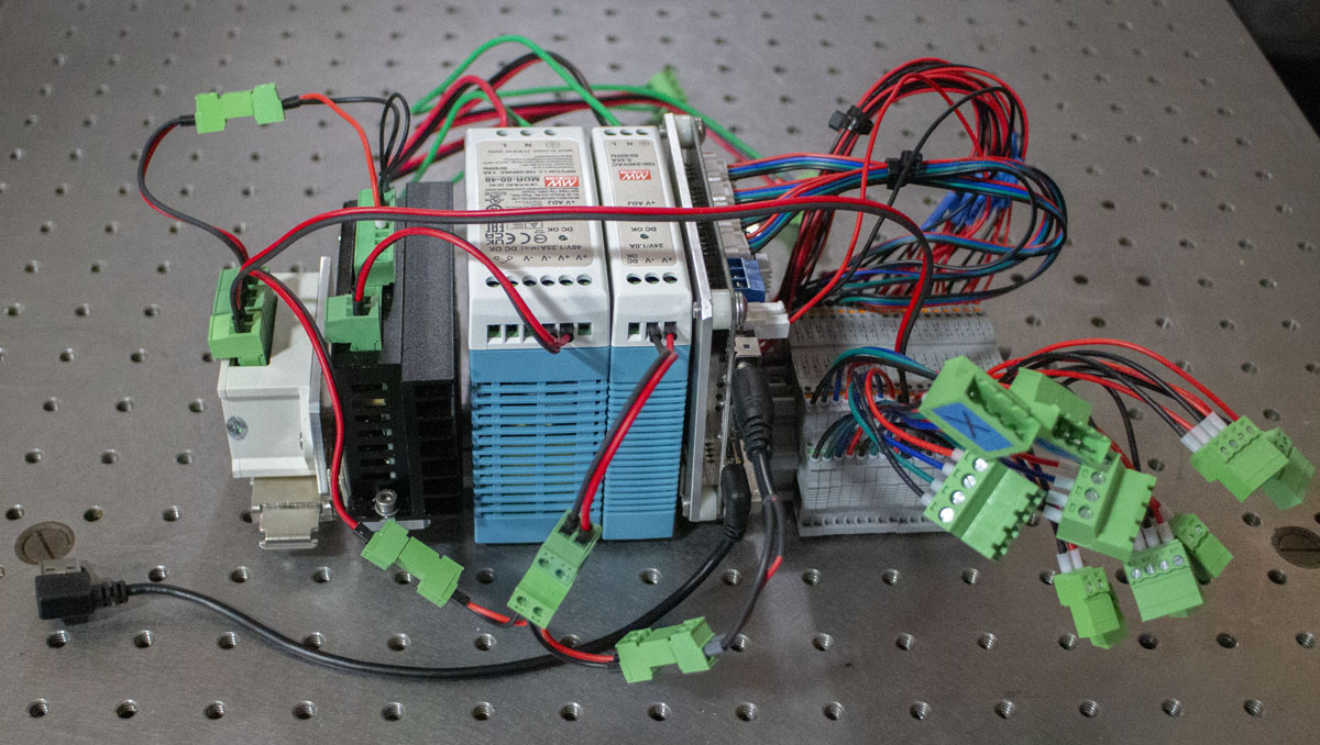
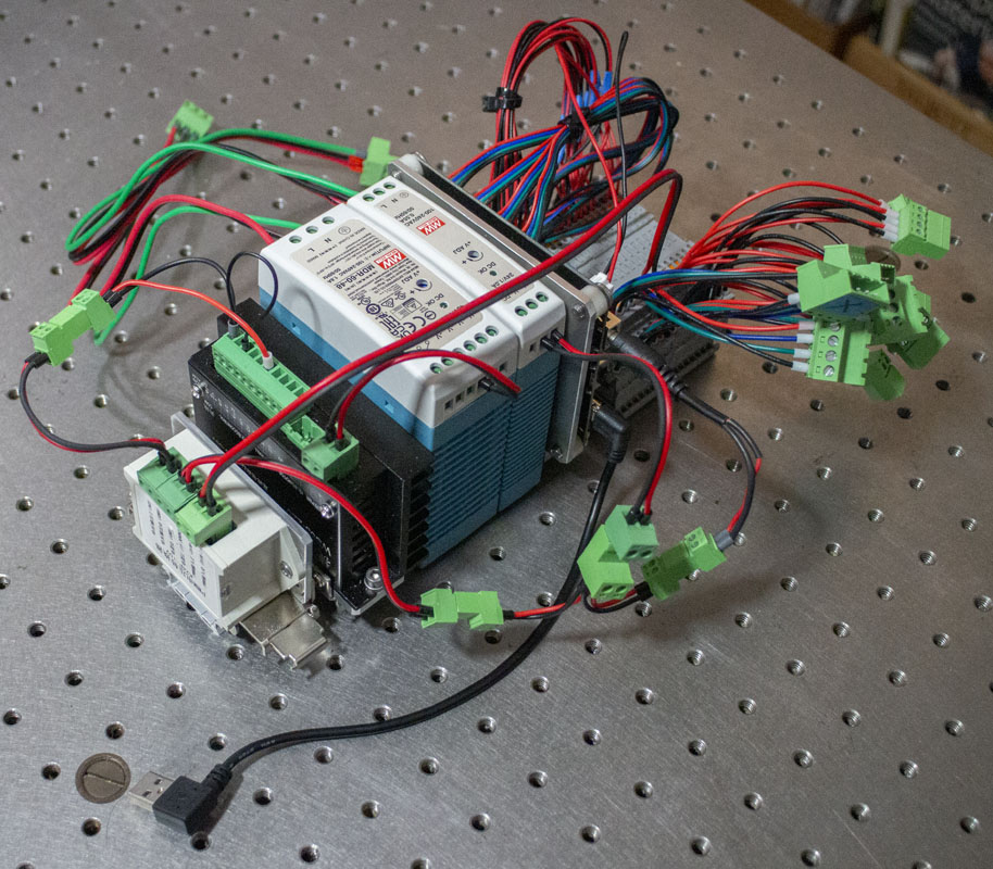
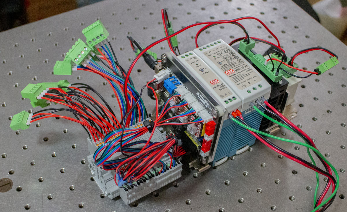
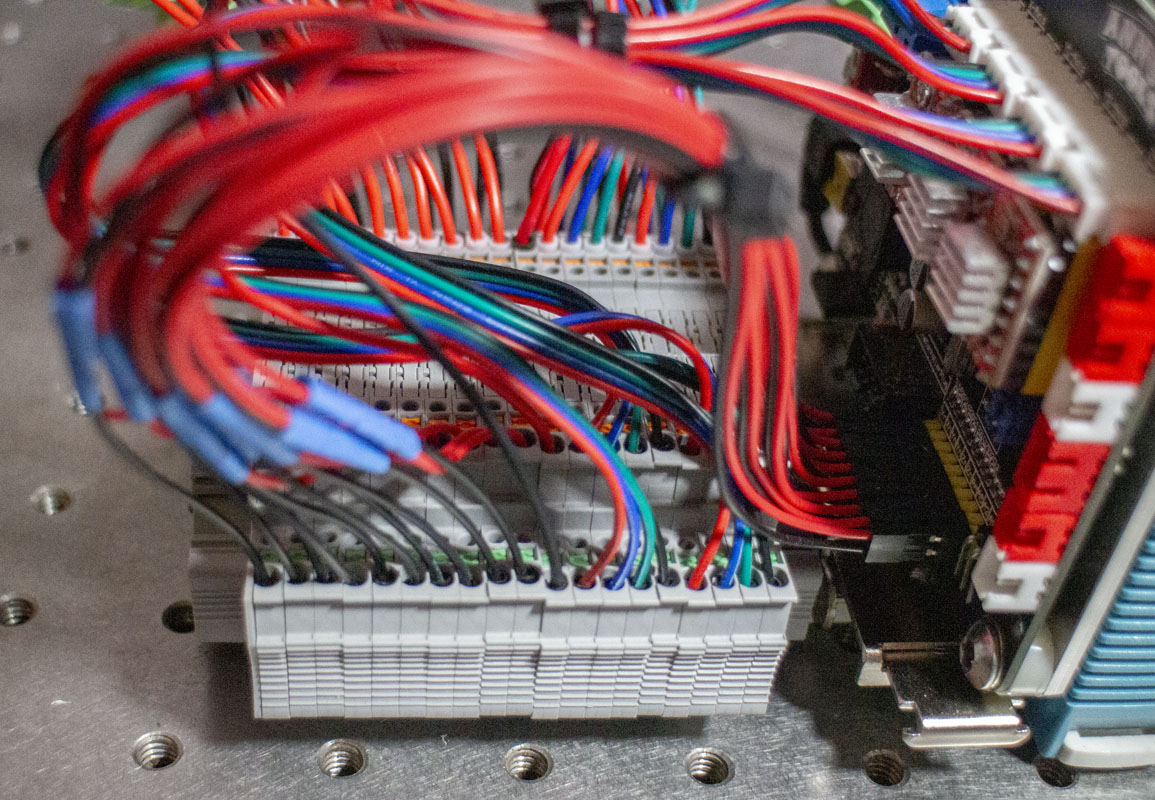
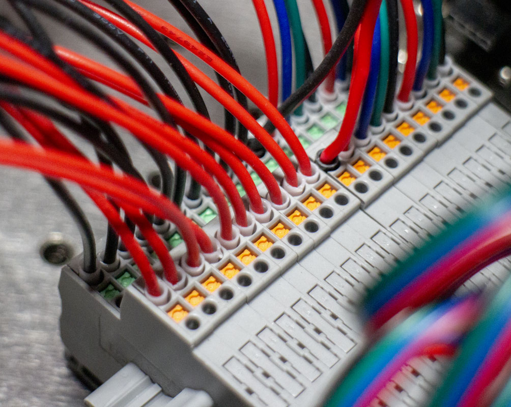
A big part of this project is working out a quality system for connecting all of the dots. We want clean, modular, and flexible. Much of that is accomplished by using a DIN rail whenever possible. With this and some good cable connections, system components are easily added, removed, or shifted around in a box.
For setting up the 35mm DIN rail, I’ve made a few decisions.
Phoenix Contact, DIN rail perforated – NS 35/ 7,5 AL PERF 2000MM VPE – 0843107
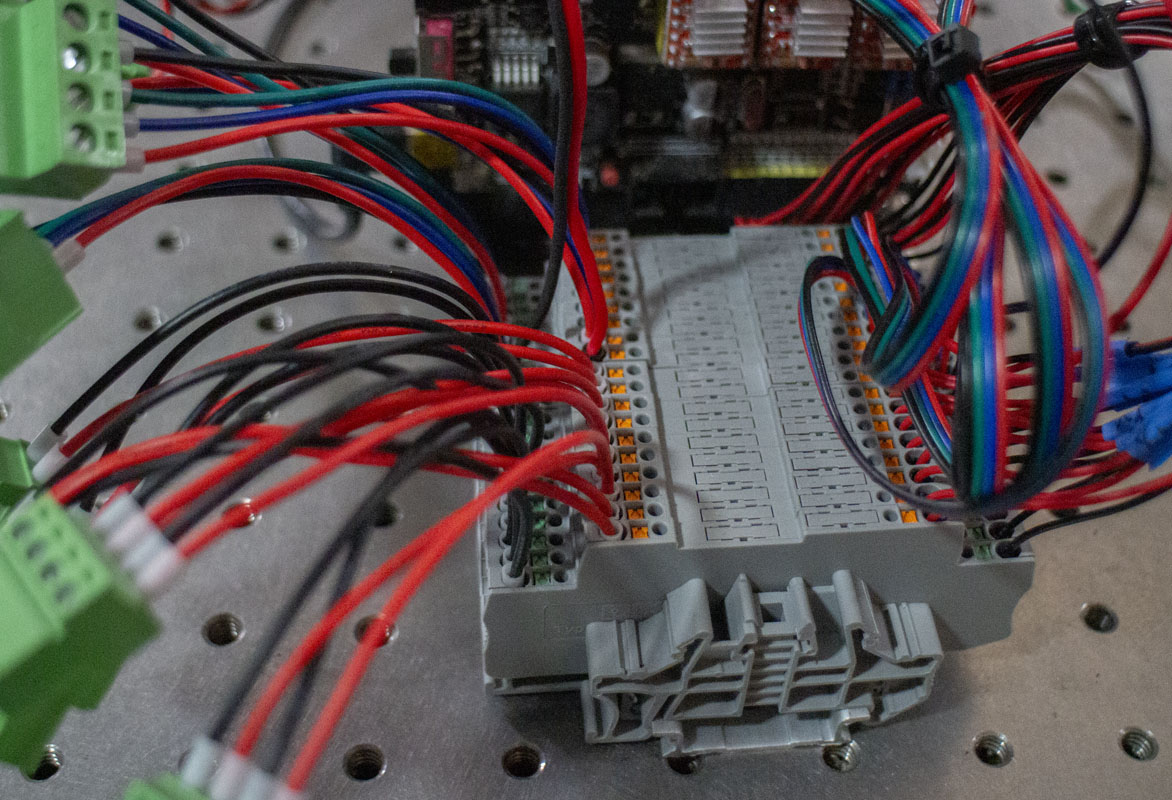
Phoenix Contact, Feed-through terminal block – PTT 1,5/S-2L – 3210356, $2.90 ea x 18
Phoenix Contact, End clamp – CLIPFIX 35 – 3022218, $1.52 ea x 6
Phoenix Contact, End cover – D-PTT 1,5/S-2MT-0,8 – 3210353 – $1.14 ea x 1
Winford Engineering, DINM3o, tabs on left, $32.50 +shipping for 10x
McMaster-Carr, 18-8 Stainless Steel Hex Drive Flat Head Screw, M4 x 0.7 mm Thread, 5 mm Long, 92125A185, $11.54 for 50
The Phoenix Contact PTT terminals are 3.5mm wide and handle two terminals each. This saves an amazing amount of room. If I was really desperate for more density and was willing to spend a little more, I could use 3213713 ($5.96 ea) that could run 3 terminals each. If space wasn’t an issue and money was, single terminal Dinkle DK4N terminals. These are single terminal and 5.1mm wide and available in bulk for close to $0.30 each from many sources.
Even more space could be conserved by using 15mm DIN rails but that starts getting a little more exotic than I’m ready for now.
Some quick milling work on some 1/8″ aluminum plate will need to be done to make mount plates for the GRBL board, PMWto10V converter, and the spindle driver for fastening to the DINM30 clips.
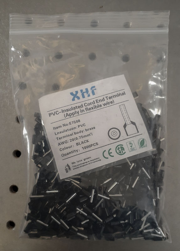
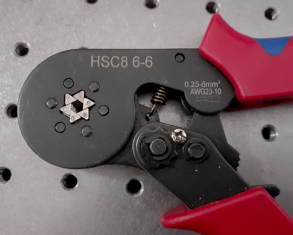
One very important component to all this wiring is using the proper crimped ferrules. These really are magic! I find that it’s nice to use a ferrule that is one size smaller than the wire it’s meant for.
XHF Insulated Cord End Terminals, Wire Ferrules Terminals, AWG 24, 1000pcs ,Black, $16.99
XHF Insulated Cord End Terminals, Wire Ferrules Terminals, AWG 22, 1000pcs ,Black, $8.78
XHF Insulated Cord End Terminals, Wire Ferrules Terminals, AWG 20, 1000pcs ,Black, $8.89
IWISS HSC8 6-6A wire ferrule crimping tool, $21.99
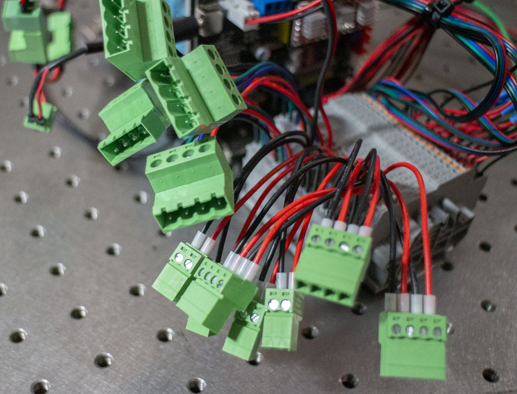
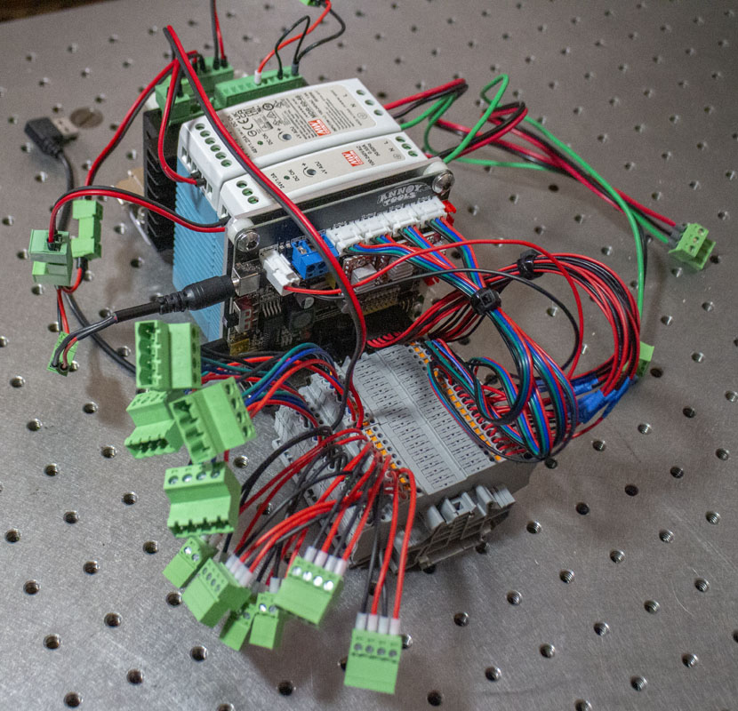
I’ve listed the little green cable disconnects that you see in the images below. They work pretty well in the box and are common. These are the primary part descriptions and numbers as provided by Phoenix Contact. You could buy these by the number at electronics parts suppliers but I highly recommend you search for similar parts on Amazon or ebay as you should be able to get them for far less than the MSRP.
Phoenix Contact COMBICON MC 3.81mm Printed-circuit board connectors, MC 1,5/ 2-ST-3,81 – 1803578
Phoenix Contact COMBICON IMC 3.81mm Printed-circuit board connector – IMC 1,5/ 2-ST-3,81 – 1857883
Phoenix Contact COMBICON MC 3.81mm Printed-circuit board connector – MC 1,5/ 3-ST-3,81 – 1803581
Phoenix Contact COMBICON IMC 3.81mm Printed-circuit board connector – IMC 1,5/ 3-ST-3,81 – 1857896
Phoenix Contact COMBICON MC 3.81mm Printed-circuit board connector – MC 1,5/ 4-ST-3,81 – 1803594
Phoenix Contact COMBICON IMC 3.81mm Printed-circuit board connector – IMC 1,5/ 4-ST-3,81 – 1857906
Phoenix Contact COMBICON MSTB Series 5.08mm Printed-circuit board connector – MSTB 2,5/ 2-ST-5,08, 1757019
Phoenix Contact COMBICON IC Series 5.08mm Printed-circuit board connector – IC 2,5/ 2-ST-5,08, 1786174
Phoenix Contact COMBICON MSTB Series 5.08mm Printed-circuit board connector – MSTB 2,5/ 3-ST-5,08, 1757022
Phoenix Contact COMBICON IC Series 5.08mm Printed-circuit board connector – IC 2,5/ 3-ST-5,08, 1786187
Phoenix Contact COMBICON MSTB Series 5.08mm Printed-circuit board connector – MSTB 2,5/ 4-ST-5,08, 1757035
Phoenix Contact COMBICON IC Series 5.08mm Printed-circuit board connector – IC 2,5/ 4-ST-5,08, 1786190
While there is a lot of flexibility on how you route and connect your wires, I strongly suggest having the COMBICON IC Series 5.08mm, 4-pin connector for power to the stepper motors. In a modular context, the stepper motors will have to connect to a real driver with the same connector type. In my case, four DM542, 4.2A drivers. These will allow me to run motors all the way to NEMA 34 (86×86) x 80 and almost any NEMA 23 (57×57). Planning this ahead of time saves a few headaches.
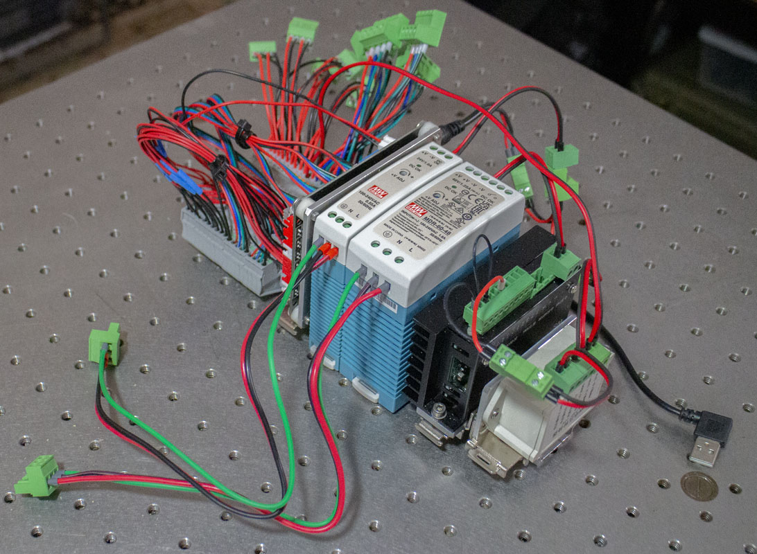
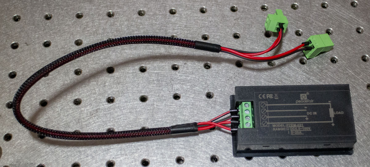
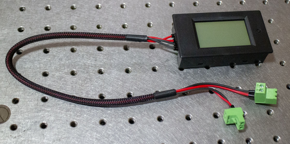
A bit of clutter was added to the wiring by adding jumpers from the power supplies for the Peacefair PZEM-031-20A ammeter ($14.59). It’s nothing fancy but it gives me a lot of good information about what is happening with consumption. I may buy a second of these so I don’t have to swap out wiring and leave them permanently in place for both spindle and steppers.
I’ve decided to continue with the Chinese convention of black, green, red, and blue for the stepper motors. Power will be black and red, 20AWG for DC and 18AWG for AC. I still need to do a bit of cleanup with my signal wires but I’m leaning toward 22AWG for these as they are small enough to soldier easily to DB15 and DB37 connectors (used in DDCS V3.1 iteration) but still large enough to crimp a ferrule and insert into terminal blocks.
In the GRBL 3018 environment, the board uses JST-XH2.5 connectors at the output for the steppers. The connection at the stepper is JST-PH2.0. Both of these can be crimped with special crimping tools like the Iwiss SN-2549. Many inexpensive kits are available for a selection of these connectors.
I’m still looking for a good labeling method for the wires. There are a couple of ideas in play and I’m going to have to settle on something soon. Good ideas are welcome if you have them.
Now that this component of the project is complete, I’m going to start setting up for the Digital Dream DDCS V3.1 CNC Motion Controller stand alone I have. Then I’ll have a better idea about the size and layout of the box.