For those familiar with my work, it’s known that I try to push my models hard in the design of my bikes and the parts that go onto them.
Because of that, equation driven construction geometry for entire bikes and groupings of parts turn into hundreds of parameters and equations for any given configuration and there are a great many configurations. Navigating this complexity has become a skill unto itself and good housekeeping within the modelspace becomes most of my workload.
This is all worth it as I can then go on very deep investigations into what makes a bike a bike. Hidden deep within the lines and the math I find things others don’t. I like that.
In the last few days while putting together my model package for a new bike, I had to find a gremlin hidden deep in my model, specifically in the area of brake caliper mounting. Something had been a little off in recent builds and I needed to figure it out before I could move forward.
Like many components in mature, complex assemblies, the sub-assembly was showing it’s age and needed some updating. It is a decade old and has seen periodic hacking. The architecture that went into building it was laborious and made errors easy to make that would have cascading results. I’ve also learned and grown in my methods in the last few years. I thought that I’d spend a few hours rebuilding it, and cleaning it up for improved use in the future.
After a few hours, found the problem in this process and improved much of how the assembly works. I then spent another day fixing and improving the overall construction. I now have a configuration for nearly any brake and mounting combination and spacing that I can drop into a bike design. This really helps when clearance is such a devil.
What I wanted to share from this is something that a lot of folks may find very valuable. A formula driven system for laying out brake mounting systems in CAD. Automating these positional values help eliminate error and improves precision in the model. I had these values from past work but an actual automated calculation in Solidworks hadn’t been done.
I work with SolidWorks so my formula use that syntax. Users of other systems may need to make adjustments.
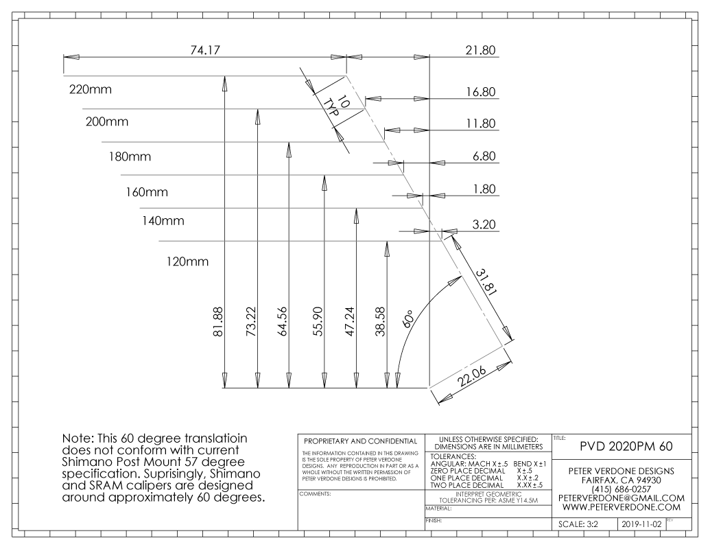
Please note that the equations for the post mount caliper locations are based off the PVD/SRAM 60 degree system. The PVD/Shimano 57 degree system isn’t very well represented in documentation so the 60 degree should be preferred. Flat mount has been defined as 32 degree from Shimano.
![]()
The driving parameters are in the form as follows:
“Rotor Size”= 160mm
“Frame Mount Size”= 140mm
Depending on the side of the mount that is being worked with, the variable can be replaced in the equations for the frame or rotor sizing. This makes housekeeping simple and clear. From that, calipers can be placed and screws mounted. Extra points as any rotor diameter can be chosen for all the snowflakes.
Referencing the diagrams above, the formulas are as follows:
“Post Mount 60 Top” = sin ( 60.0 ) * ( 51.81082007 + ( “Rotor Size” – 160 ) / 2 ) + cos ( 60.0 ) * 22.06102725
“Post Mount 60 Bolt#1” = cos ( 60.0 ) * ( 51.81082007 + ( “Rotor Size” – 160 ) / 2 ) – sin ( 60.0 ) * 22.06102725
“Post Mount 60 Bolt#2” = “Post Mount Bolt#1” + 74.17mm
“Post Mount 57 Top” = sin ( 57.0 ) * ( 50.58523019 + ( “Rotor Size” – 160 ) / 2 ) + cos ( 57.0 ) * 24.7423622
“Post Mount 57 Bolt#1” = cos ( 57.0 ) * ( 50.58523019 + ( “Rotor Size” – 160 ) / 2 ) – sin ( 57.0 ) * 24.7423622
“Post Mount 57 Bolt#2” = “Post Mount Bolt#1” + 74.17mm
“Shimano Flat Mount R Top” = sin ( 32.0 ) * ( 39.43246374 + ( “Rotor Size” – 140 ) / 2 ) – cos ( 32.0 ) * 5.77328361
“Shimano Flat Mount R Bolt #1” = cos ( 32.0 ) * ( 39.43246374 + ( “Rotor Size” – 140 ) / 2 ) + sin ( 32.0 ) * 5.77328361
“Shimano Flat Mount R Bolt #2” = “Flat Mount R Bolt #1” + 34mm
“SRAM Flat Mount R Top” = sin ( 30.5 ) * ( 39.57007816+ (( “Rotor Size” – 140 ) * 8.5/10/COS( 30.5 ) ) / 2 ) – cos ( 30.5 ) * 4.73908368
“SRAM Flat Mount R Bolt #1” = cos ( 30.5 ) * ( 39.57007816 + (( “Rotor Size” – 140 ) * 8.5/10/COS( 30.5 ) ) / 2 ) + sin ( 30.5 ) * 4.73908368
“SRAM Flat Mount R Bolt #2” = “SRAM Flat Mount R Bolt #1” + 34mm
“Shimano Flat Mount F Top” = sin ( 32.0 ) * ( 25.75824217 + ( “Rotor Size” – 140 ) / 2 ) – cos ( 32 ) * 3.12457365
“Shimano Flat Mount F Bolt #1” = cos ( 32.0 ) * ( 25.75824217 + ( “Rotor Size” – 140 ) / 2 ) + sin ( 32 ) * 3.12457365
“Shimano Flat Mount F Bolt #2” = “Flat Mount F Bolt #1” + 70mm
“Sidewinder Height Plane” = sin ( 32.0 ) * ( 25.22832290 + ( “Frame Mount Size” – 140 ) / 2 ) – cos ( 32 ) * 3.97262175
“Sidewinder Bolt #1” = cos ( 32.0 ) * ( 25.22832290 + ( “Frame Mount Size” – 140 ) / 2 ) + sin( 32 ) * 3.97262175
“Sidewinder Bolt #2″= “Sidewinder Bolt #1” + 39.0mm
Excuse that I am forced to use 8 decimal places. This is a re-engineered system that repairs incorrectly defined standards. Were this done correctly from the start, far neater values would be possible.
Documentation on this topic is terrible. I’ve discussed all of this at length in the past. Through a long process of discovery, I’ve found that lateral locating of the caliper mount should be done from the rotor, not the dropout. Without that, systemization is impossible. This is really important. The mount follows the rotor, not the other way around.
The difficulty here, obviously, is that while the brake components stay the same, the way that the wheels clear the frame is different. In both wheels, the wheel is changed symmetrically. In the front, a different lateral positioning is used as more room is available.
“Hub Spacing”= 148mm, 142mm, 110mm, or 100mm
“Rotor Face from Center”= 55.25mm (148), 53.25 (142), 44.50 (110), 39.50 (100)
“Post Mount Screws from Inner Rotor Face”= 9.55mm
“Flat Mount Screws from Inner Rotor Face”= 12.20mm
“Sidewinder Face from Inner Rotor Face” = 20.20mm
Here’s another fancy frustration saver for the equations field:
= IIF ( “Hub Spacing” = 148 , 55.25 , IIF ( “Hub Spacing” = 142 , 52.25 , IIF ( “Hub Spacing” = 110 , 44.5 , 39.5 ) ) )
This will allow for the return of the rotor location given the 4 most popular hub spacings. I can add more as time goes by or my directions change.
Those lateral values are based on the Shimano centerlock specification (10.5mm (F) & 18.75mm (R)) for the inner face of the rotor to the hub end. The Shimano specification for 6-bolt is 10.25mm (F) & 18.25mm (R) from to the hub end. Thus, calculations specifically for 6-bolt would be 0.25mm (F) and 0.50mm (R) outboard from what I’ve provided. I believe that the centerlock is the preferred universal in the current era. Different rotor thickness can inform the builder as well, Shimano is based on 1.75mm.
The benefits of this are quickly made clear as I can test and confirm several designs in just minutes.
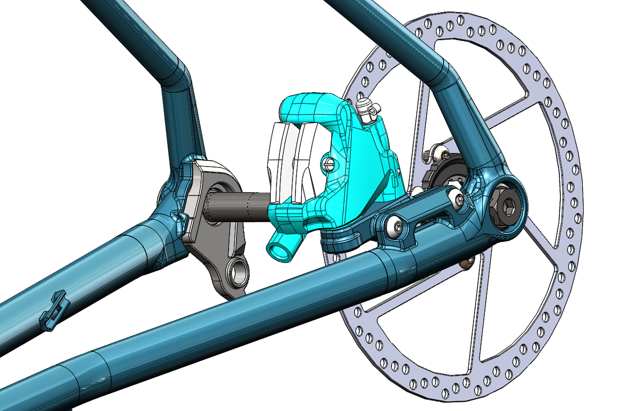
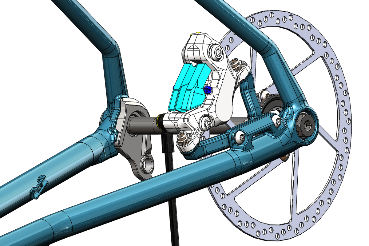
Spoiler: It was pointed out that somewhere in all the hashing and thrashing at my models, the rotor was reversed in it’s orientation. That has been fixed but is such a minor detail in context that it is not worth updating the graphic.