I got lucky. Really lucky. Less than a second later and I would have been tumbling head first down a 15 foot chute of chunk. It would have been very bad, possibly deadly.
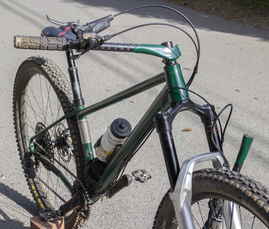
The 3D printed stem on my 2022 PVD MiG-31 Firefox broke catastrophically on my third ride. This is the second catastrophic failure of handlebars on the third ride, AKA ‘the charm’. The first time was a failure of the carbon fiber tube that has been rectified. This time it was the the 3D printed stem.
I was just starting to get up to speed on the new bike. Getting used to having a suspension fork and big tires after all of the rigid all road-testing that I’ve been doing in the last year was taking some time. I had done a survey ride on the bike around Tamarancho and down Solstice. I had done some double black diamond descents on Tam: Tamalpa and 999esses.
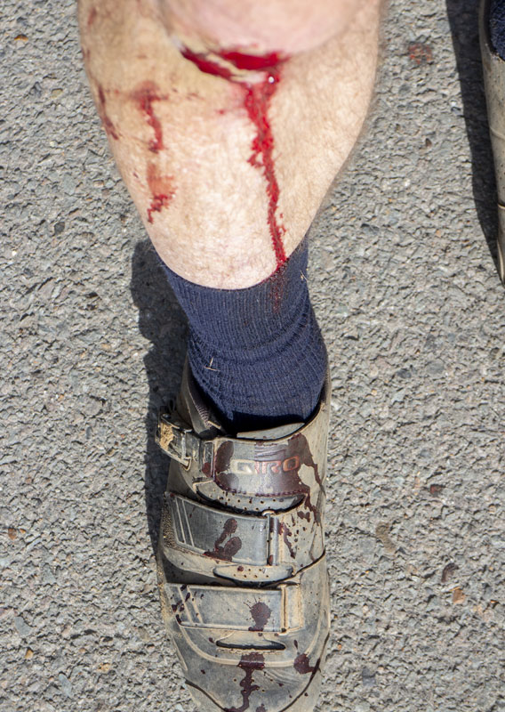
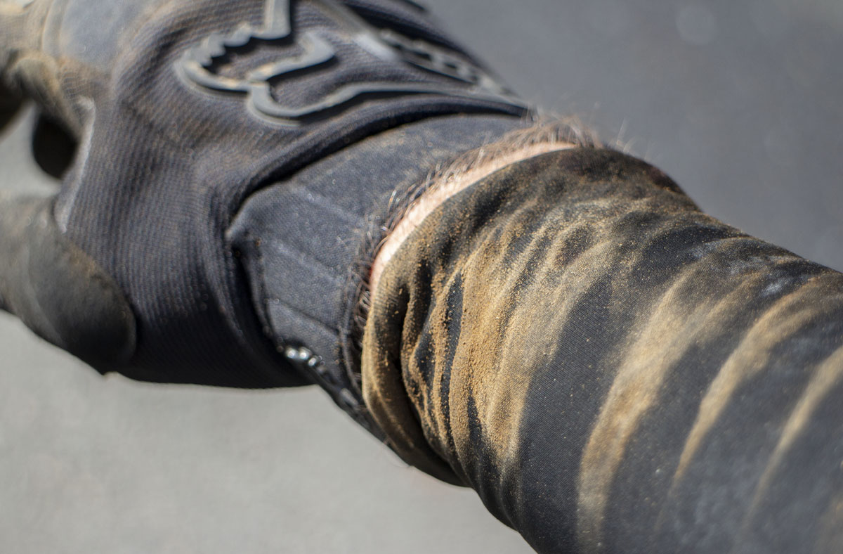
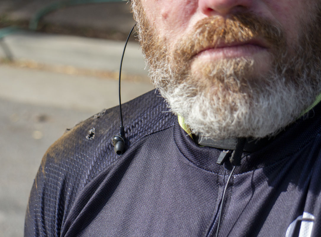
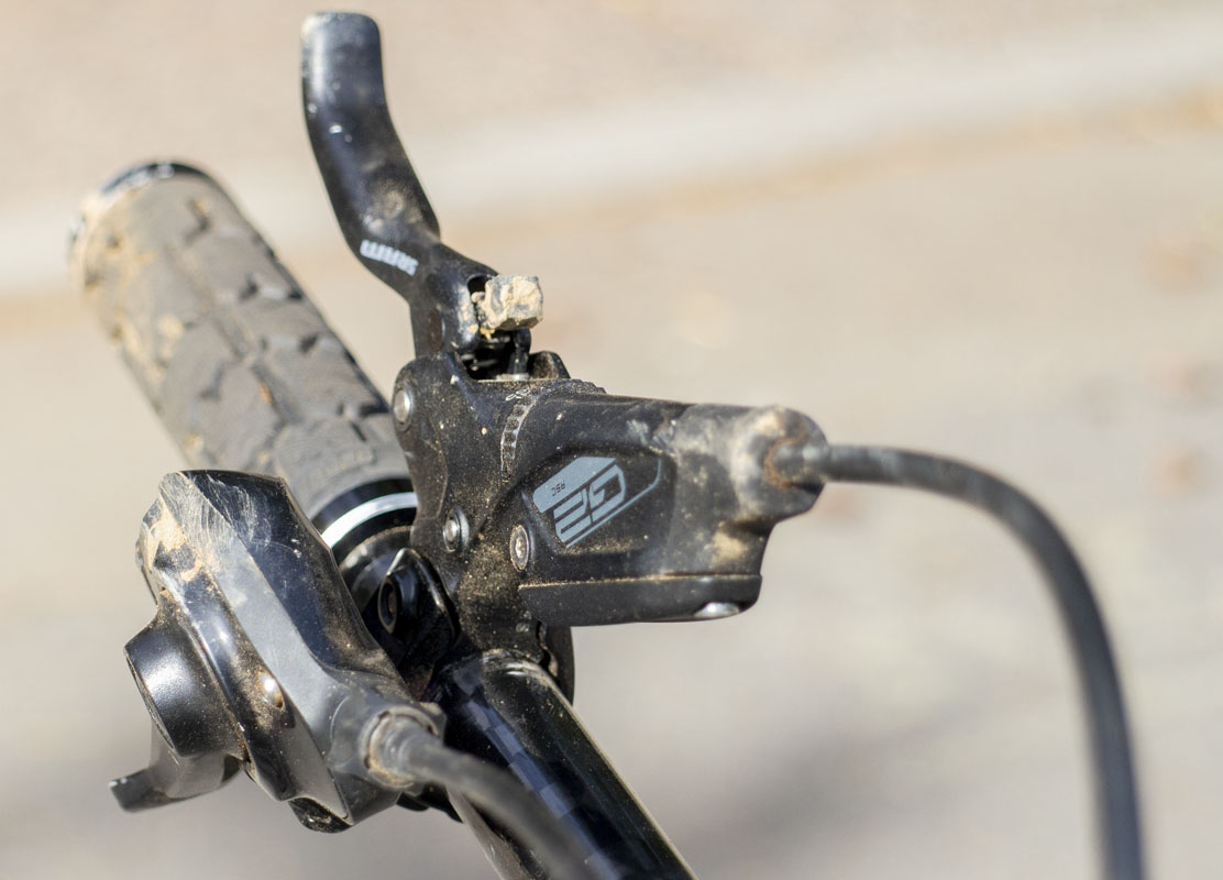
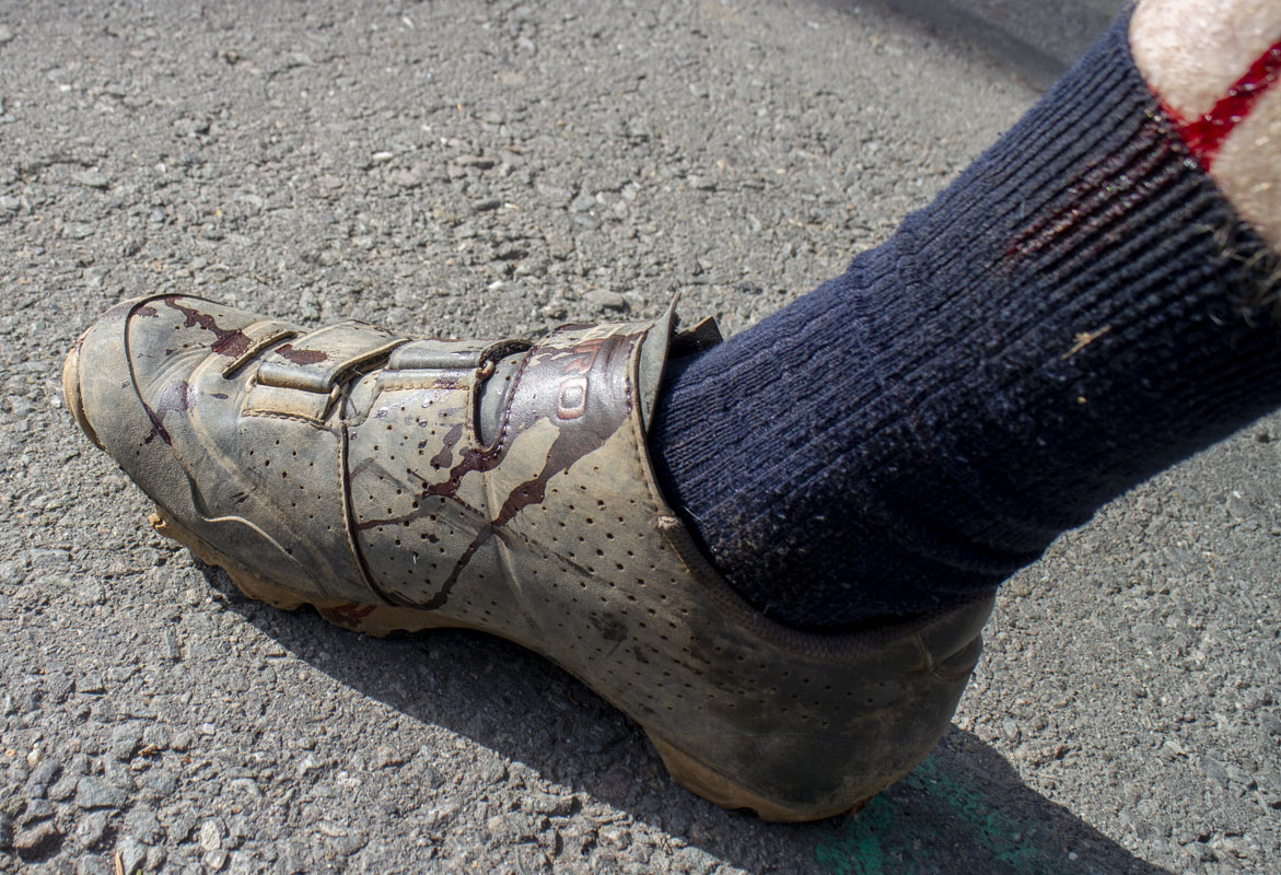
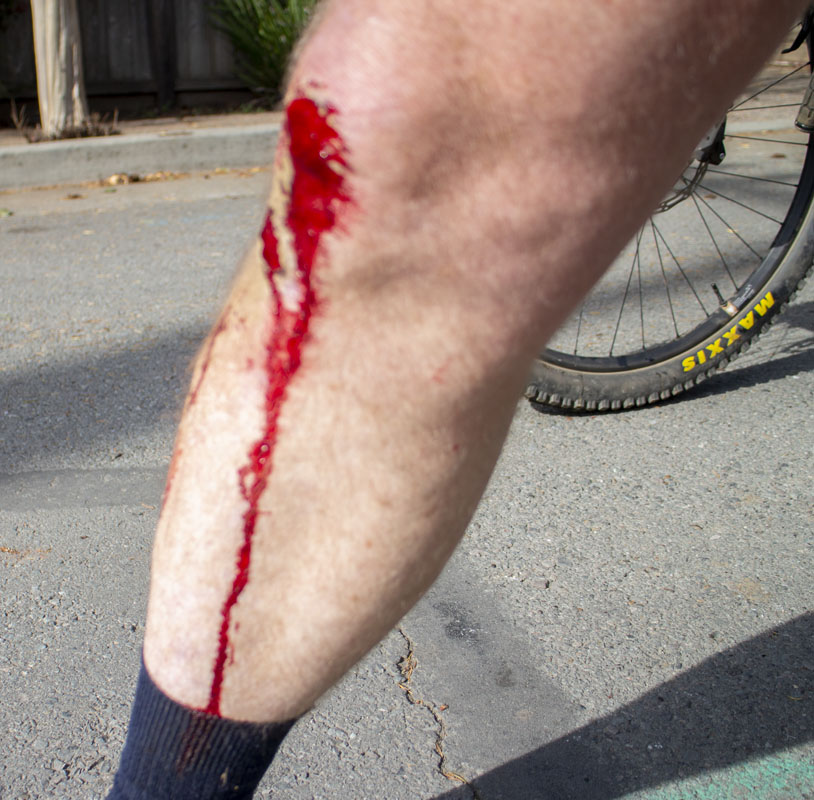
On this day, I was almost done with the fork tuning and was taking an easy lap around Tamarancho and down Hobo trail. It was on Hobo when things went wrong. I entered the trail hot and fast, as I like to do, getting a little loose and wild down the staircase area. In the next traverse, I was feeling smooth so I kept the throttle wide open. I charged the two gnarly switchbacks and the gap jump clean and smooth. Into the fast motorway and over the log jump, again, fast and smooth. I’m coming into the big chute and starting to set up for the abrupt left entry. I begin braking to check my speed and set up for the corner…and it happens. I watch my left hand push down into the tire as I see the tire coming up at me. Then the obligatory tumbling slam, and the pain. Banged up and torn, it was a hard hit. Anyone that has had a real failure-initiated crash knows how bad this can be. Aside from a lot of blood, a sprained thumb, and bruising all over. I was all right. Once again, I was fucking lucky.
No forward progress comes without a cost. That’s a law of nature. We’re working with new technologies and ‘new’ materials. This is a bumpy process.
We saw printed handlebars snap in the 2020 Tokyo Summer Olympics. The Australian cycling team had a similar catastrophic failure during a race. They also got lucky as nobody was seriously hurt. This was a titanium printed part that was engineered and produced at Bastion Cycles, a group in Australia with their own printer and a huge amount of experience in this medium. HERE is the engineering report on the failure.
While we use 3D metal printing in many parts of modern high-end bicycle construction, the stem/handlebar seems to be where the issues come up. In discussions around my latest failure, Adam Prosise probably summed it up best, “There are a lot of unconstrained forces in that area.” I think that there’s something to this. In most other parts of the bike, even fork crowns, there are constraints on how the forces go through the part. The handlebar is not like those other places. This is the engineering challenge.
There are questions of print quality, engineering, and other issues that come up here. I’ll come back to those later in this post but I’d like to get to my immediate action plan for repair.
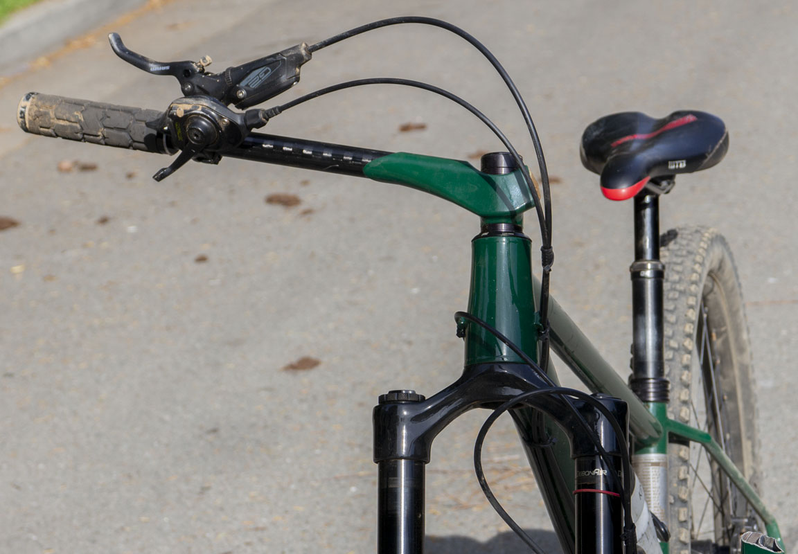
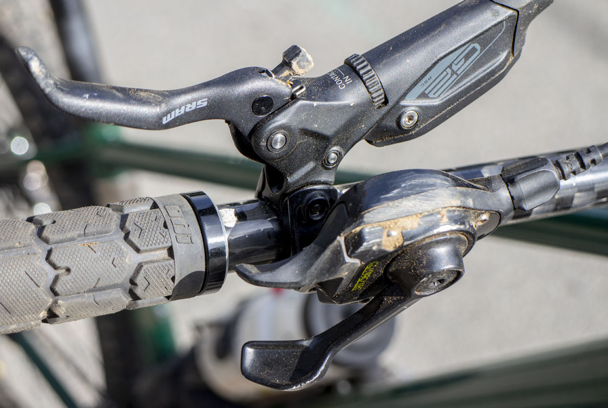
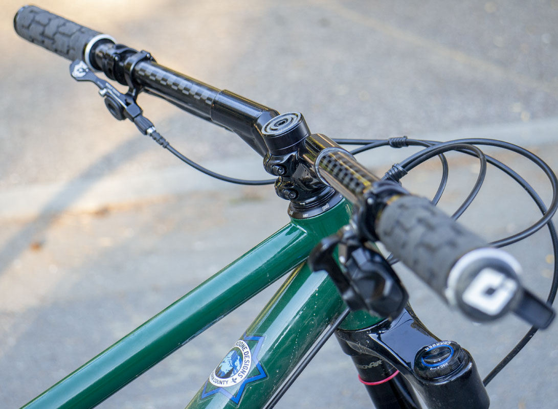
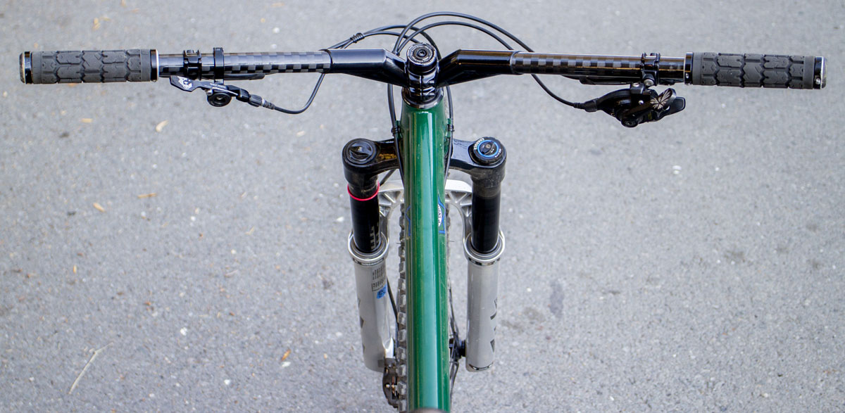
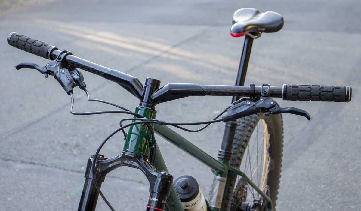
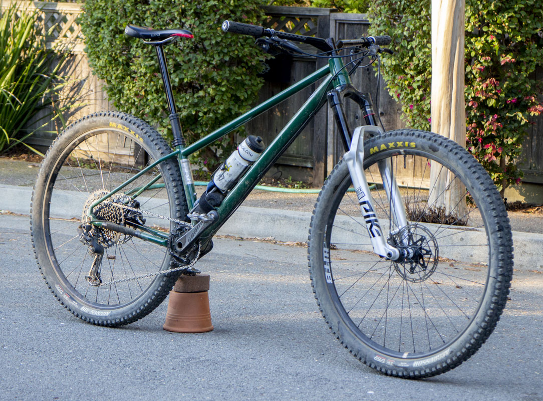
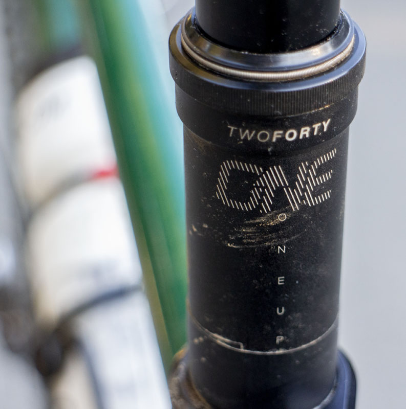
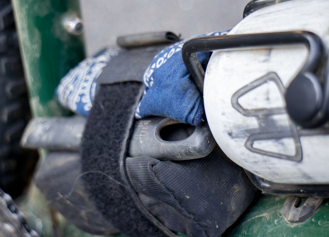
Still in tuning mode, I needed to get the Firefox back online and into the dirt. This is a challenge as my designs do not rely on commercially available stems and bars. What I did have in the shop were the handlebars from my Warbird. These bars had some geometry differences from the broken setup, but with a pile of spacers I could get them to just about work. The real issue here was that the 9 degree sweep of the Warbird bars put the grips a bit more forward of what the 14 degree sweep of the Firefox. It would put my 51 year old body into far more of an aggressive riding position than I would like, but it works and I’ve been able to continue riding the bike as I tune the fork and evaluate the new 240mm dropper post.
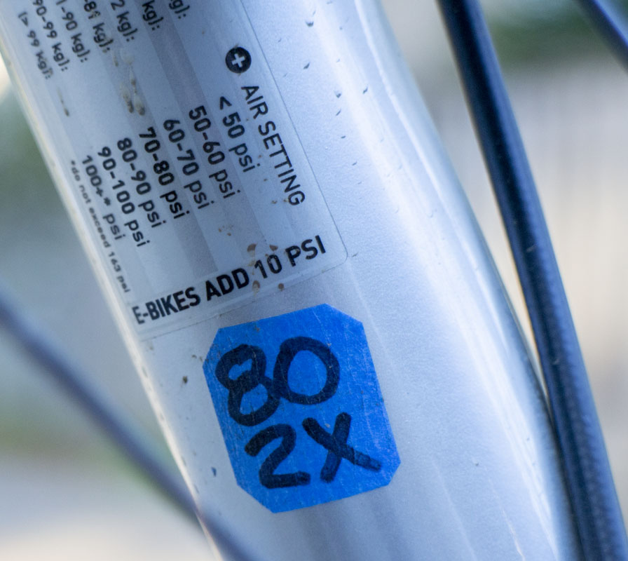
I’m homing in on 80psi with two volume spacers in the little 150mm Pike fork. Debating a slight air pressure reduction. The fork tuning corrected a bunch of early riding issues as it is riding a bit higher in rough descents. It’s now fairly plush at the tips but ramps well at the end. Still thinking of playing with oil.
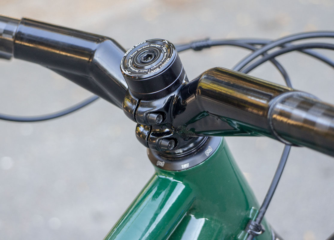
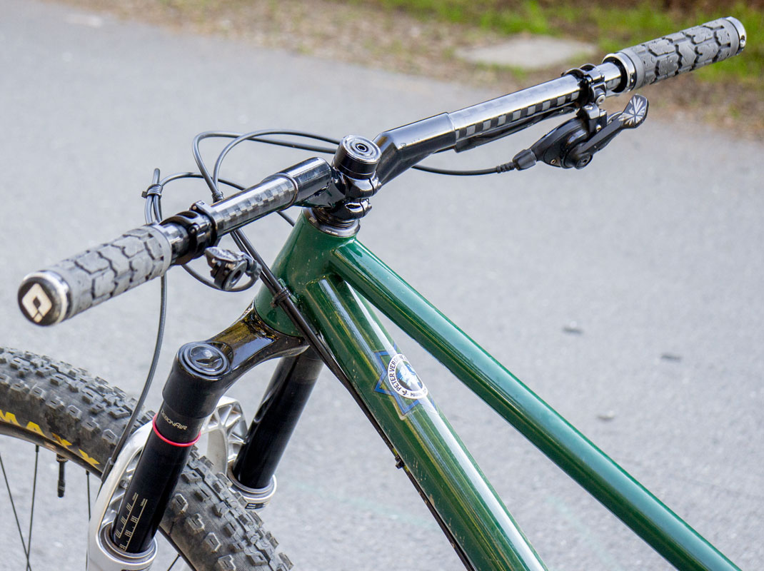
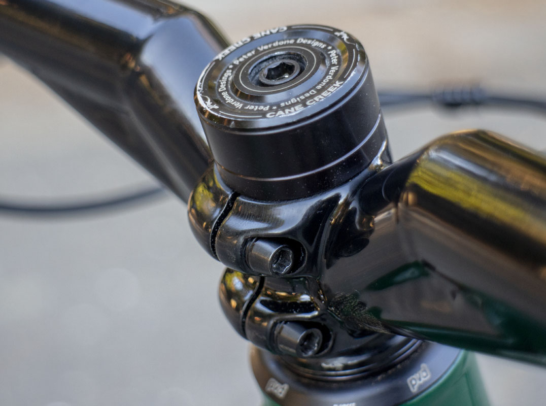
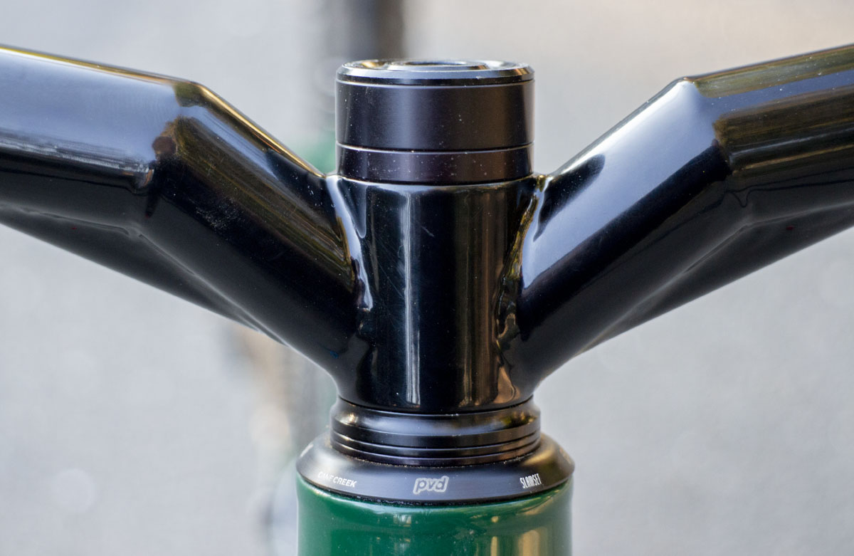
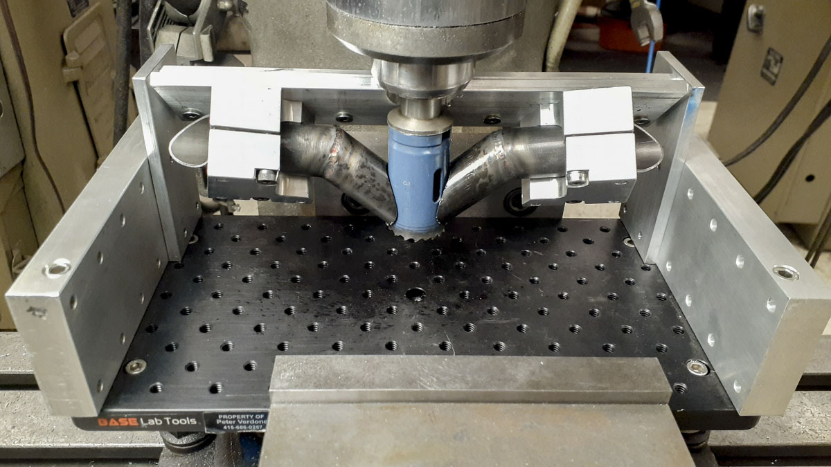
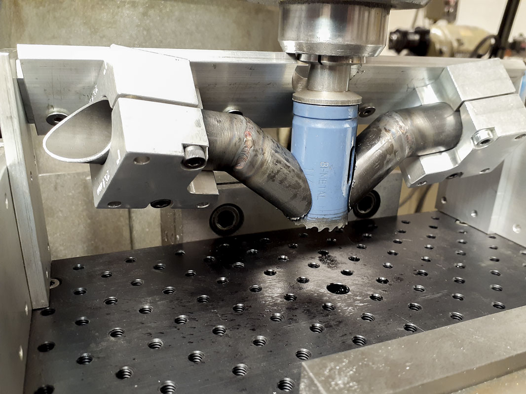
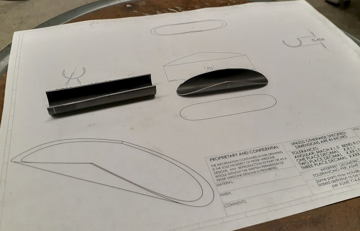
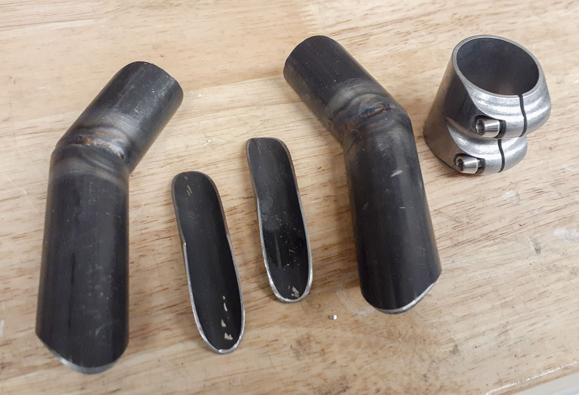
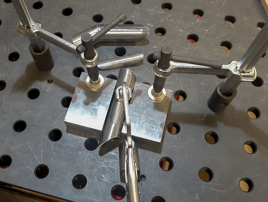
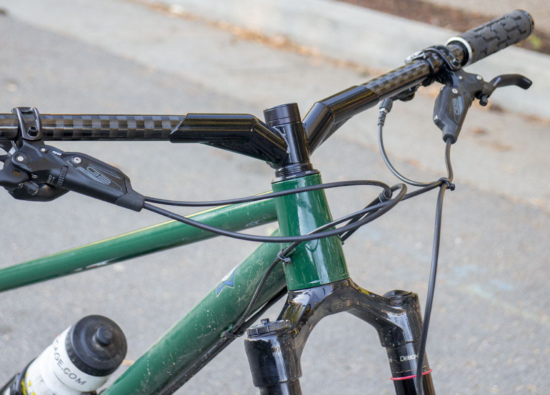
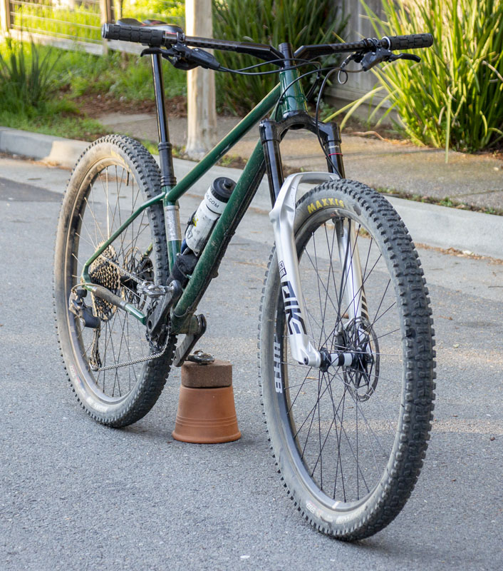
Rather than rush a new printed design, pay a ton of money, and wait on another shipment from China, I chose to fabricate a new version of the stem. There’s an old expression, “never let a good crisis go to waste.” In a way, the failure had me looking at fabricated solutions differently than I had before and I came up with a fairly simple design that I could make with material on hand. If I had it powder coated black, I could have it back to me relatively cheaply and quickly.
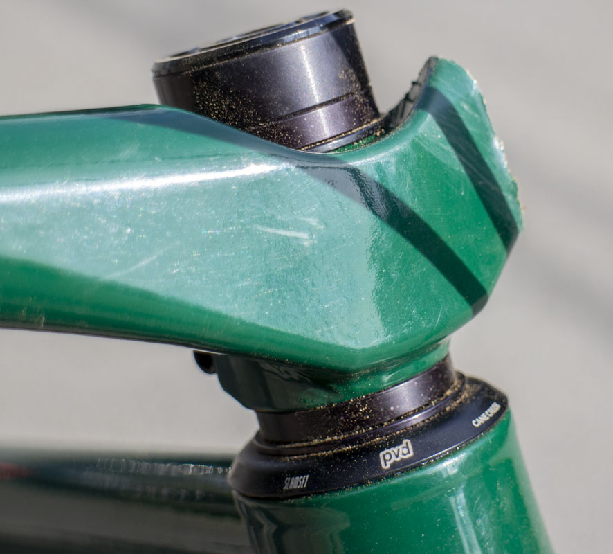
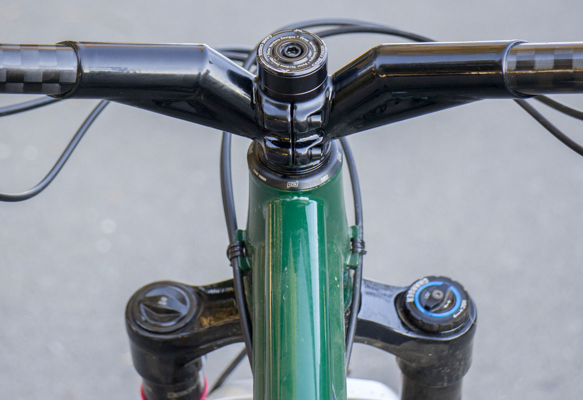
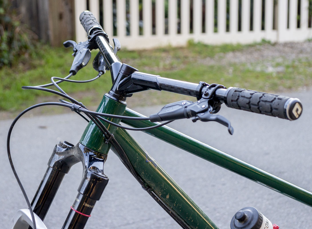
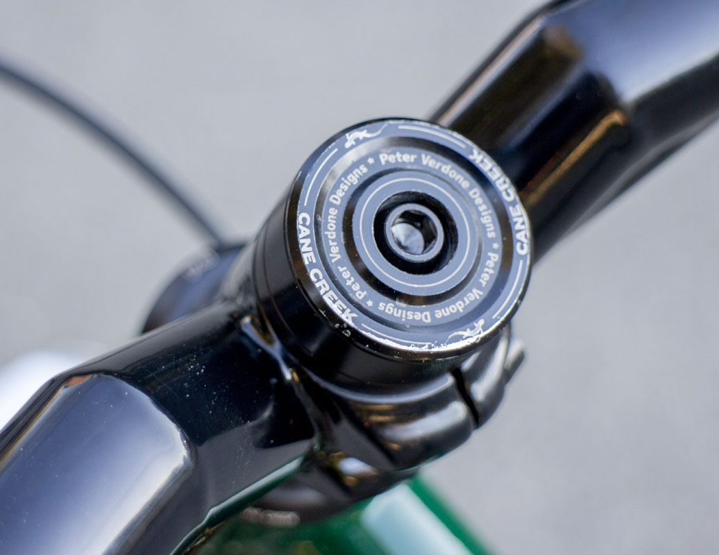
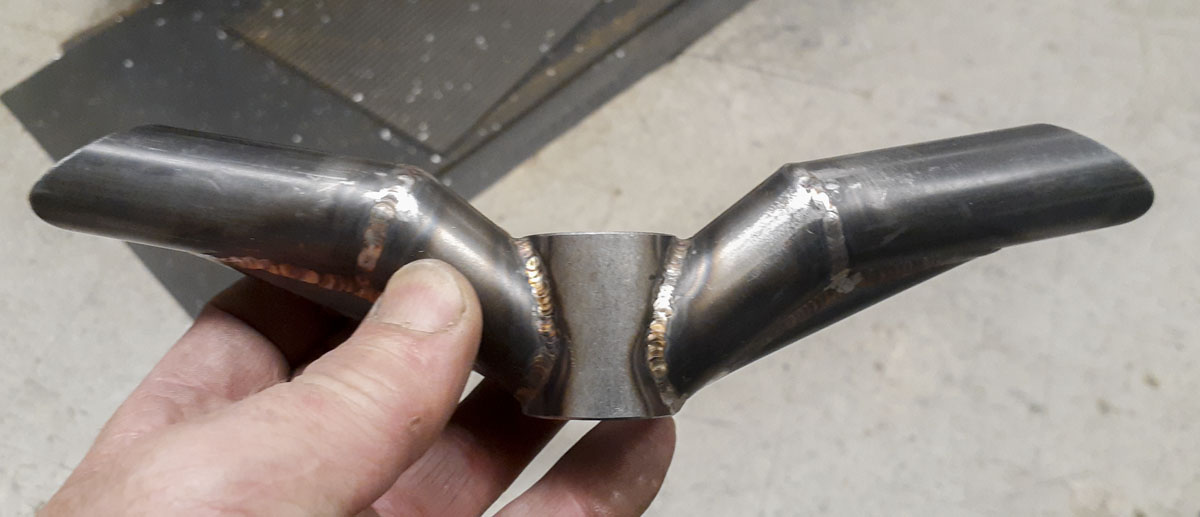
The bike is back up and running with handlebar geometry that I can enjoy. It also looks kinda cool. We’ll see how this type of bar performs on the trail and go from there.
I’m considering going with black paint on all of my stems from now on. Color match is pretty sweet but a standard black would allow more mixing and matching to try new things while still looking composed.

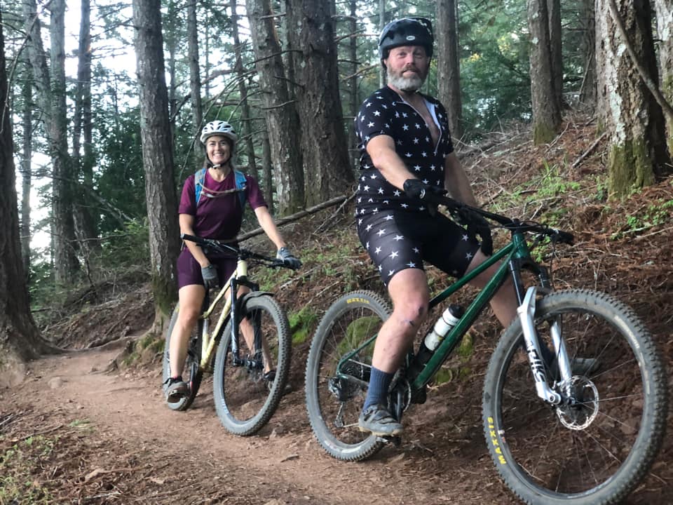
Windy and I were doing a first test loop with the new bars around Tamarancho and we bumped into Brian Berringer. Got to do half a lap with him which was nice. He took a photo of the two of us.
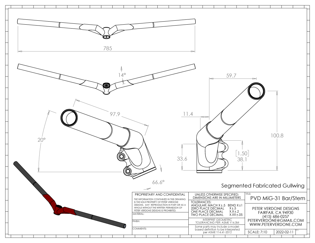
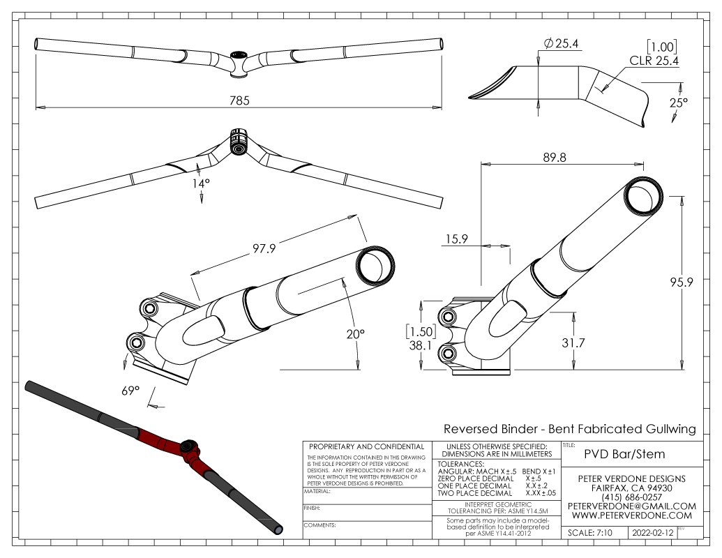
Now, what I made here is not what I would have preferred to make in a fabricated version of this stem. It’s what I had to do given what was easily on hand. If I had the correct tubing mandrel bent at the tight radii required, I could have done a much cleaner version. A bend of this type is expensive. It’s not something that can be done without a large and expensive mandrel bending machine. I may send out some RFQs in the next few weeks to see how much it would cost to get some of this on hand as I think that it would be nice. Cheaper and quicker than printing with a more predictable failure mode.
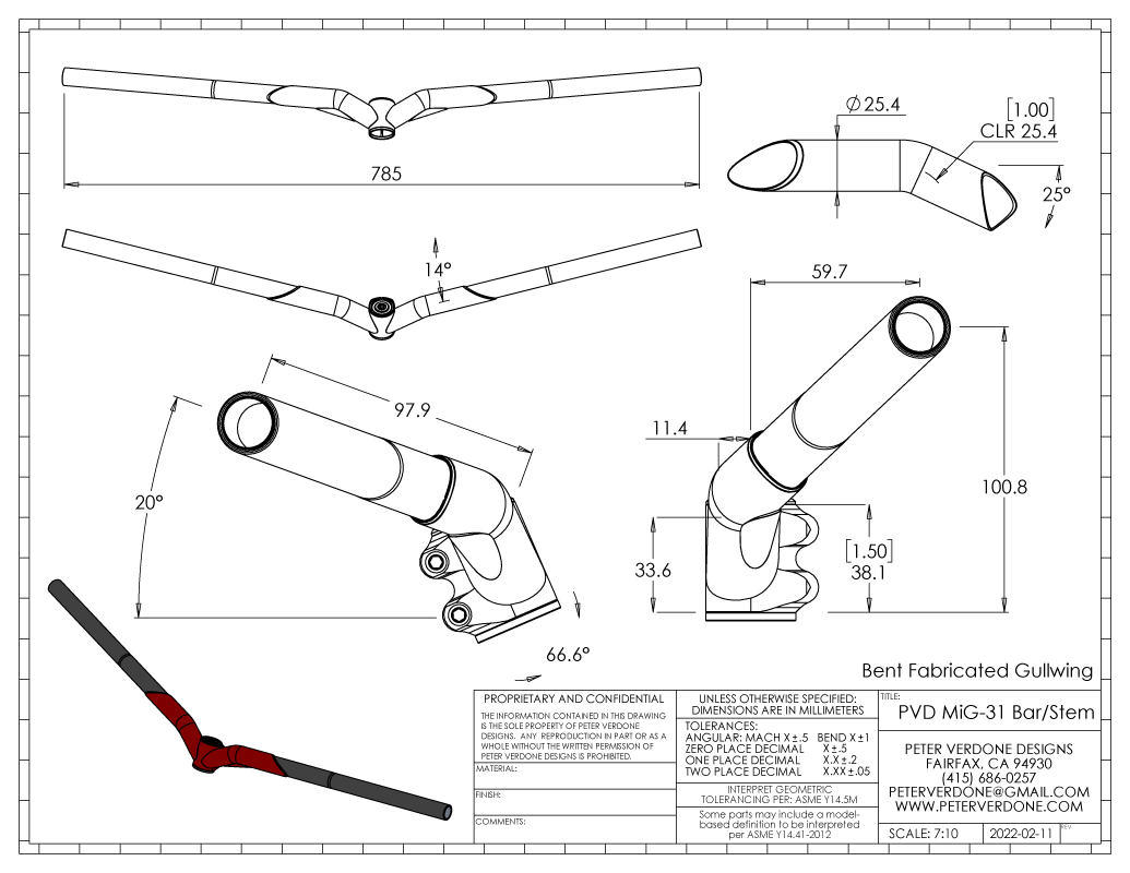
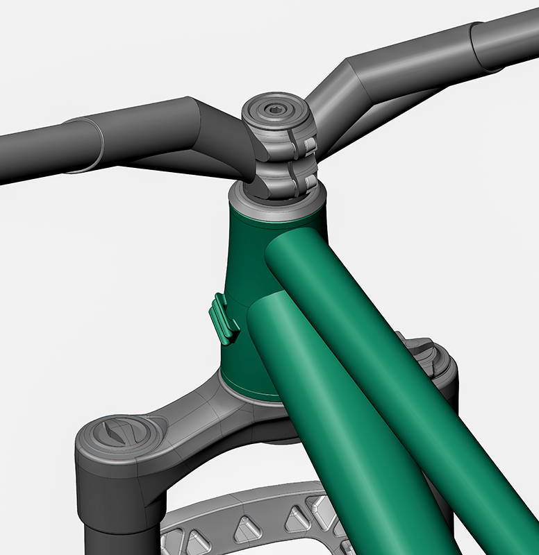
Another nice thing about this design is that it could buy me a bit more head angle clearance with a strong connection. I drew the bars with a reversed binder and (all other parameters constant) a 69 degree head angle. Same 25 degree bent section. This shows that there is a range of uses for that part if I have it made. It also doesn’t quite look bad. Of course, mechanical trail and flop will change with this angle adjustment but none of the other chassis or fit parameters would. This is definitely the direction for XC and all-road bikes to go.
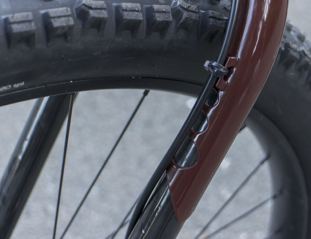
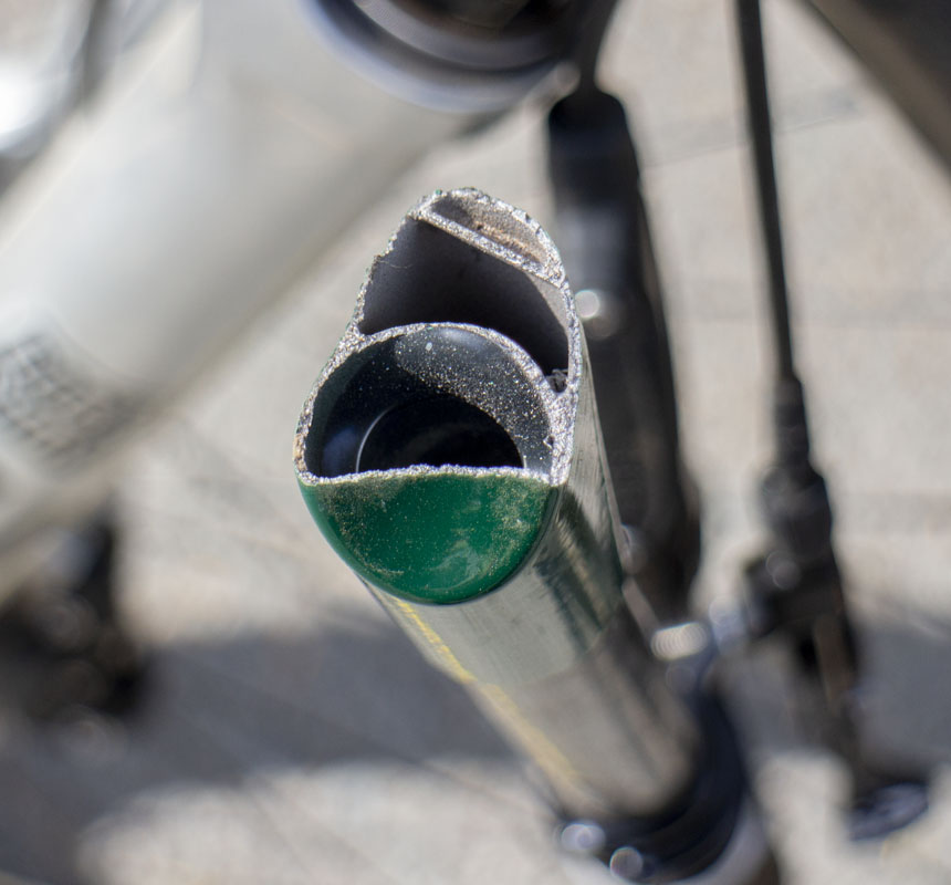
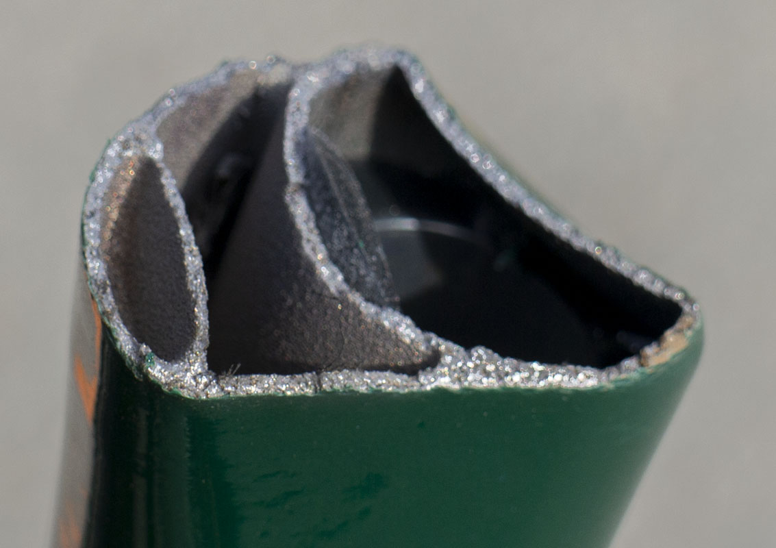
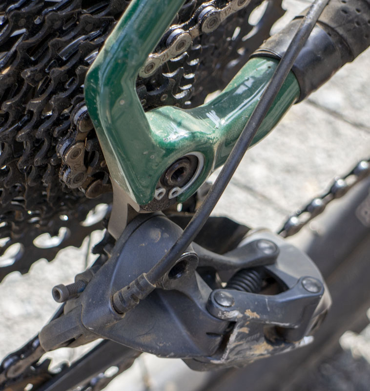
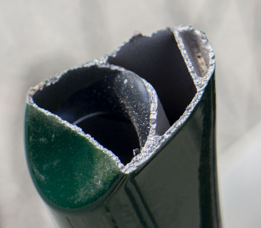
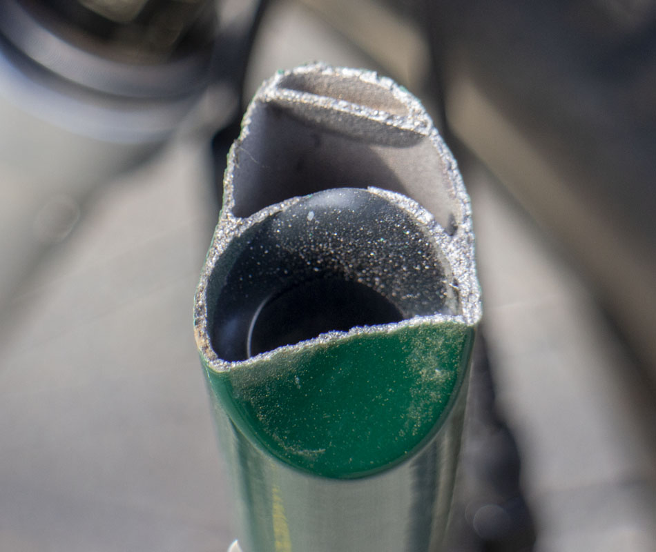
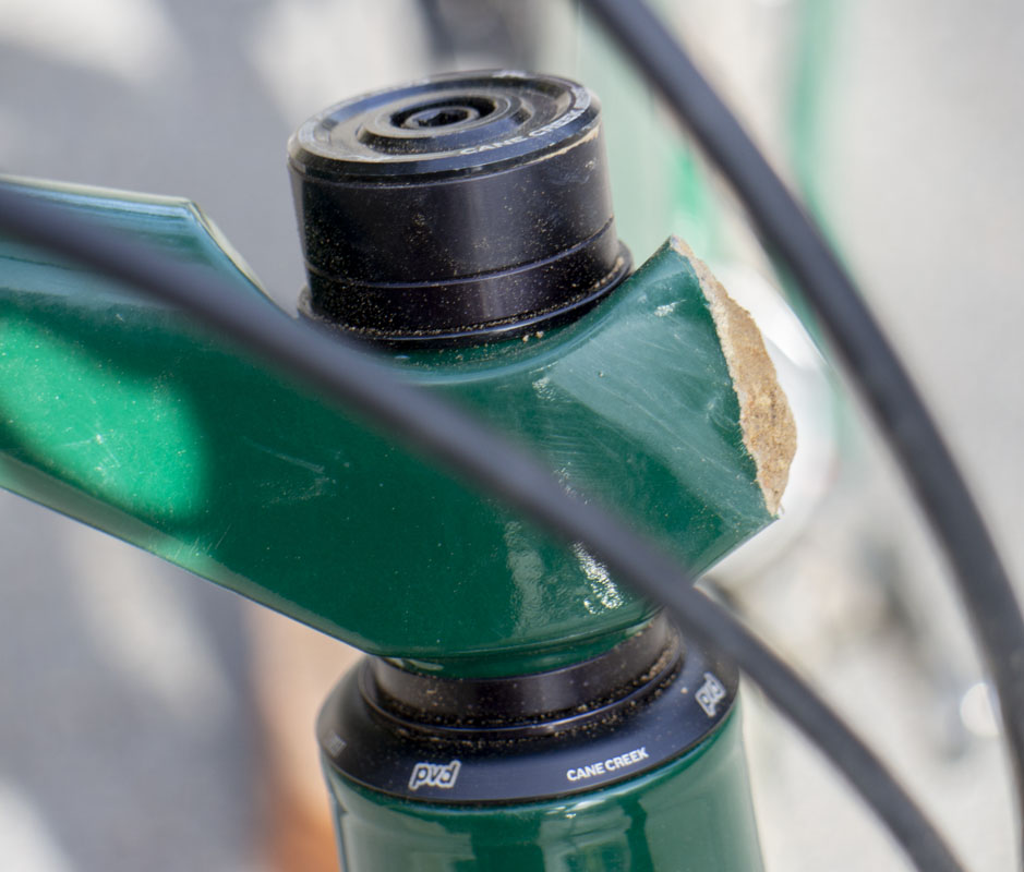
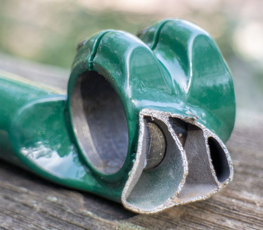
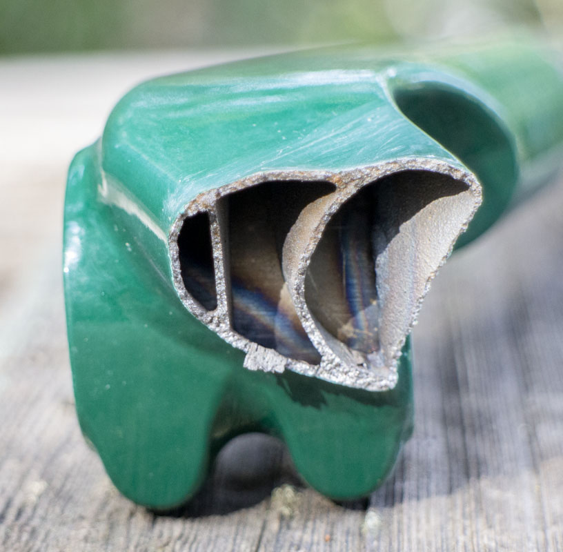
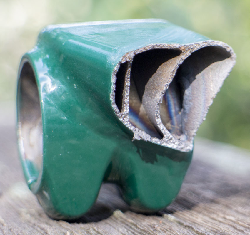
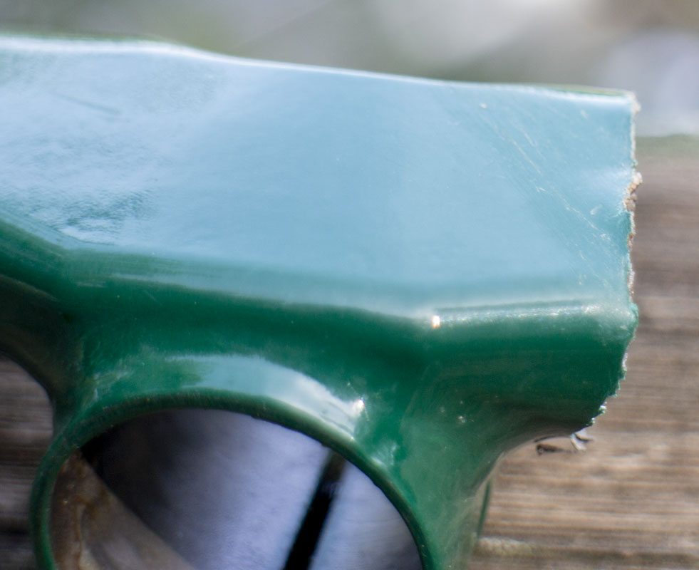
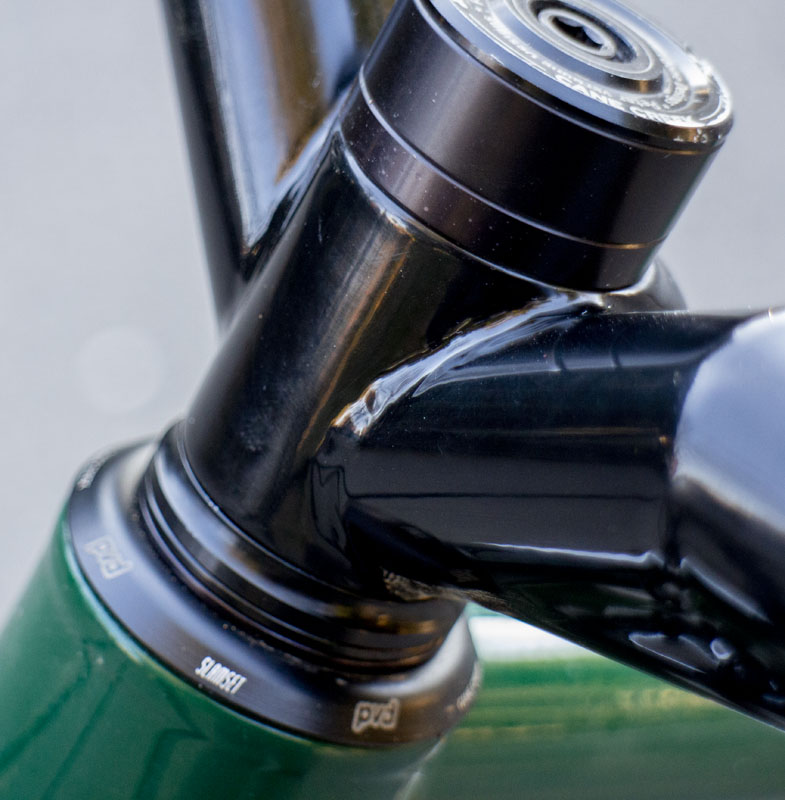
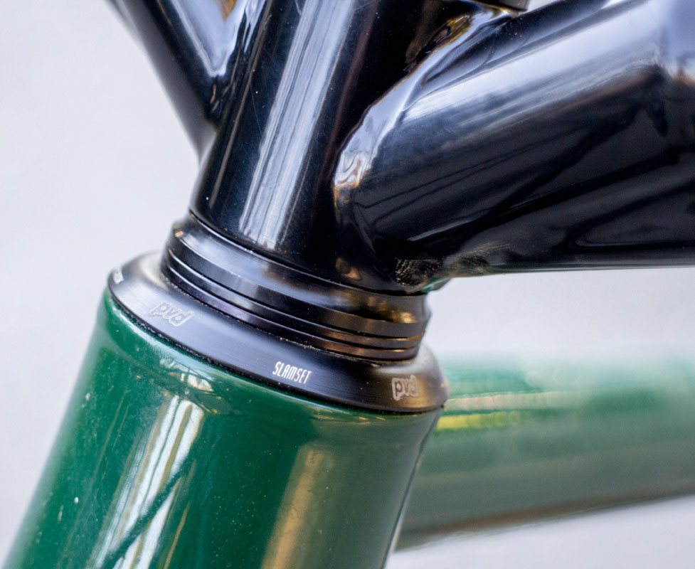
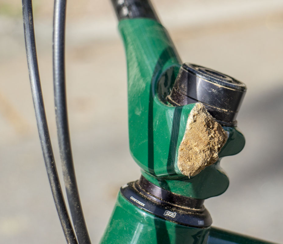
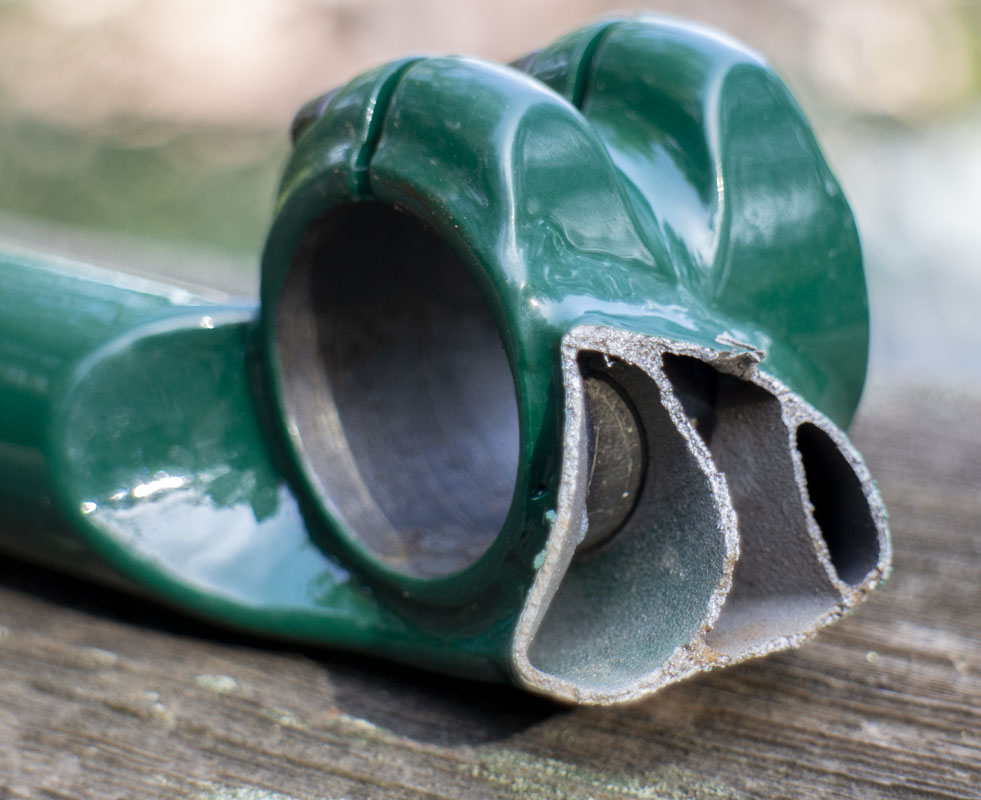
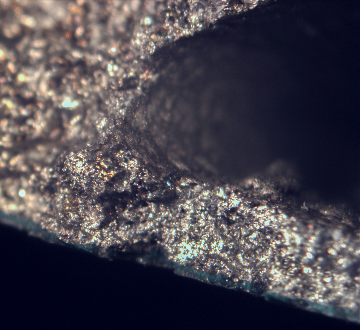
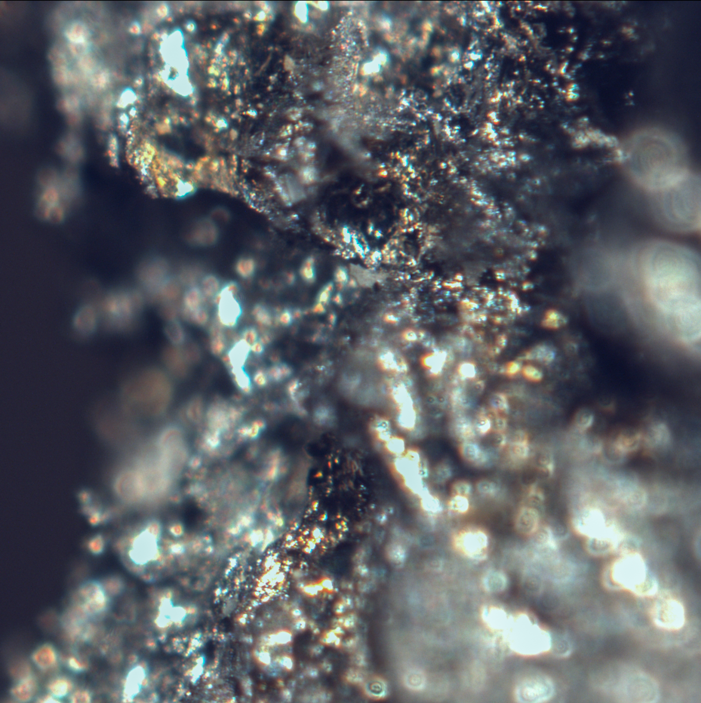
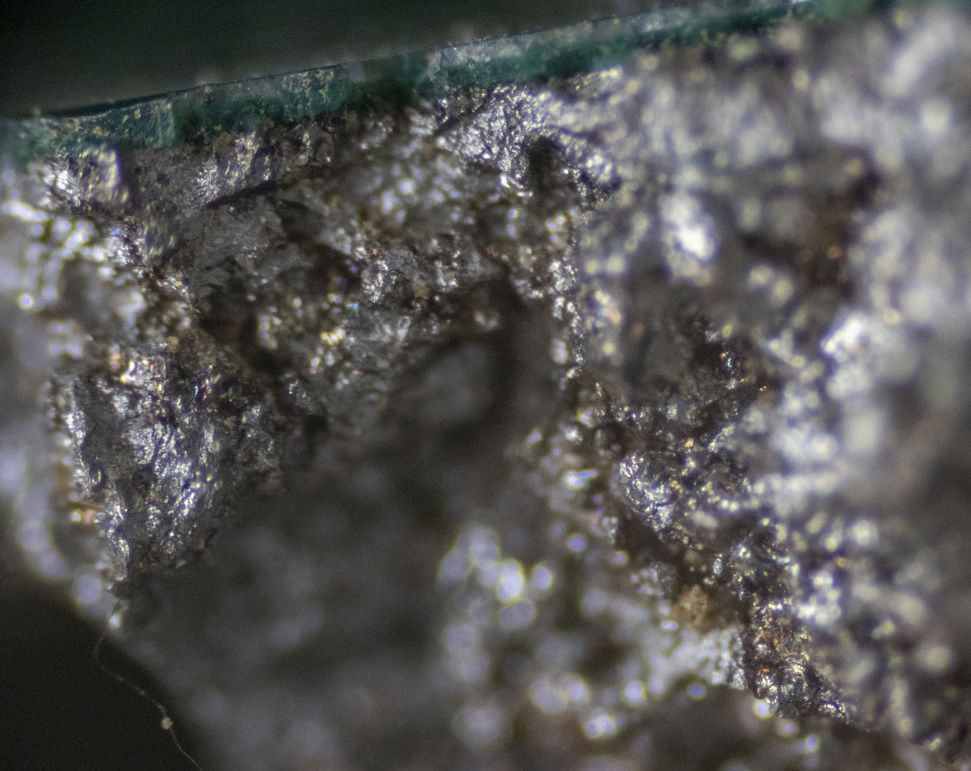
Now we can look closer at the failure of the printed part. The failure seems to have started at the rear of the part and tore toward the front as you’d expect with the hardest loading. The top rear corner being the ‘origin’. The real failure may have been in another part of stem but the catastrophic collapse seems to have started there. That initiation point is close to the weld but doesn’t look to be in the weld. Very little of the broken region is in the weld heat-affected zone.
The failure continues straight through the part as if totally unimpeded. It’s like it just cleaved off a section. This is strange stuff.
For reference, powder coating temperatures get up to 400 degrees Fahrenheit for melting the powder. If powder has to be burned off in a re-paint, the temperature will get up to 750 degrees. This was virgin metal so the temperature was quite low for powder coating.


![]()
Let’s look at possible causes of this:
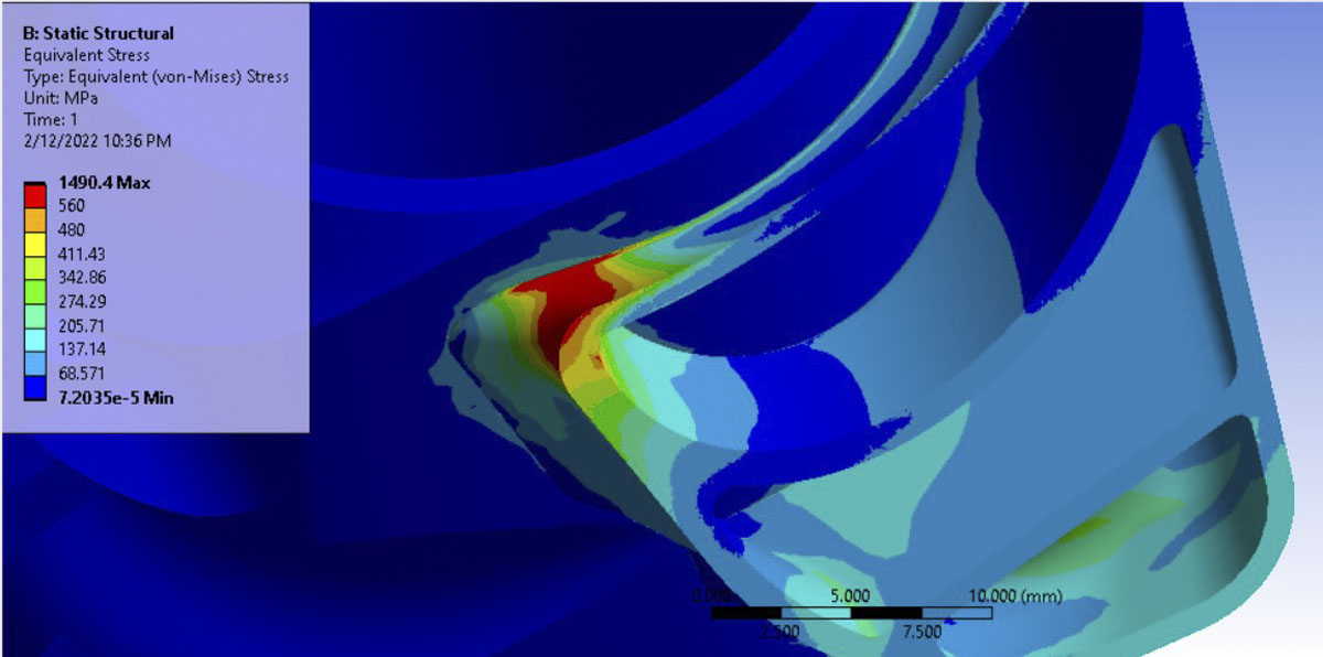
Bad engineering: It’s always good to imagine that you are the cause of any failure and that you fucked something up. We start here. The part is 316L LPBF-3DP. The part was designed with additional internal supports to prevent this kind of failure. The theorized initiation of the failure is a hot spot with stresses rising there. This is because of the complex geometry in the system and minimal space to work. To save cost in the printing and keep known strong parts in place, I had chosen to weld to the PMW SP2002: Steel Stem Steerer Clamp.
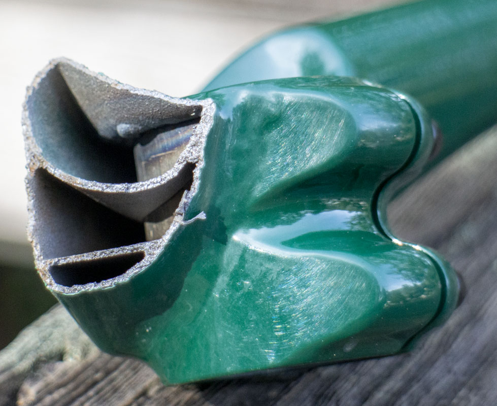
I designed this part with 1.2mm wall around the bars and 1.0mm wall in the rest of the structure. The fork crown on the TIE had 1.5mm walls. Is it that I was just way to thin in this part for an appropriate safety factor? My next design will use much thicker walls and probably include the binder in the print so that I can reduce significant stress risers. I’m about done with catastrophic handlebar failures.
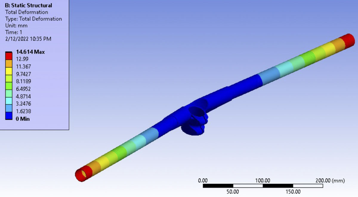
Angus Morison helped with some FEA to look at what is happening here. He’s an engineer at Polaris and has access to some fancy software (Ansys Mechanical) that I don’t. We see that the theorized ‘hot spot’ is in fact a hot spot. At a very specific point, the stresses to get much higher than they should. Still, this would explain a small crack forming over time but not such a complete and sudden failure very early in the use of the stem. Angus is siding with reversal of the binder clamp (like I show in the drawing earlier) to provide a way of reducing this issue and smoothing out the stresses in an easier way. I’m going to put a lot more serious thought into this.


Poor Printing: In LPBF (Laser Powder Bed Fusion) production, powdered metal is fused by a fiber laser through a galvanometer laser scanner. The part is removed and cleaned to be put to use. Sometimes it is processed in a heat treatment furnace to eliminated some residual stresses or modify the grain structure but that isn’t always required.
I discussed the printing issue on this part with Nick Bass, a senior engineer at Cumberland Additive, who specializes in additive manufacturing metal parts for aerospace. He was gracious enough to give some very good information that can help others as well;
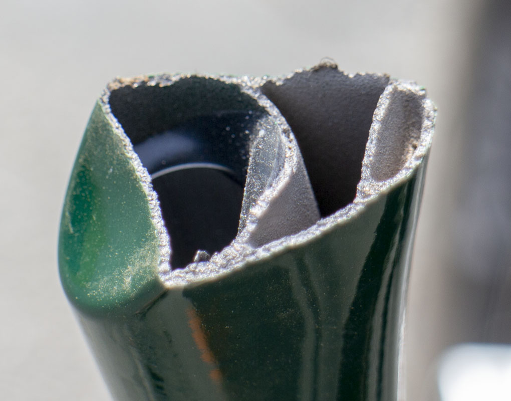
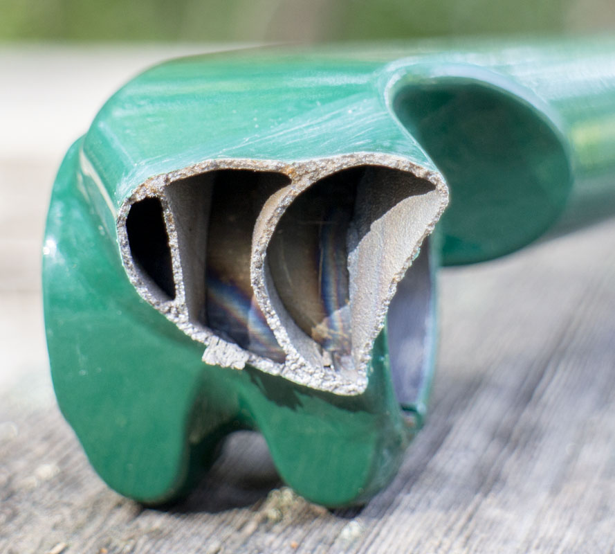
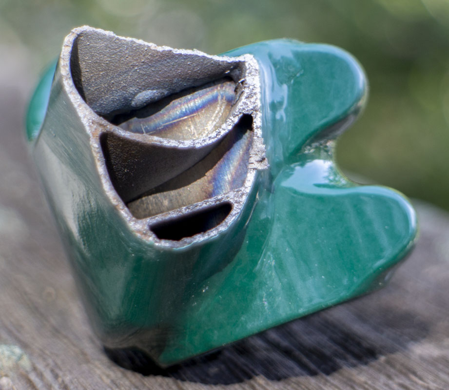
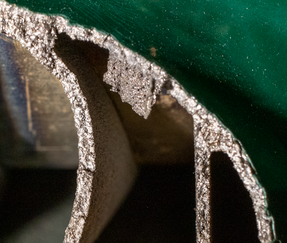
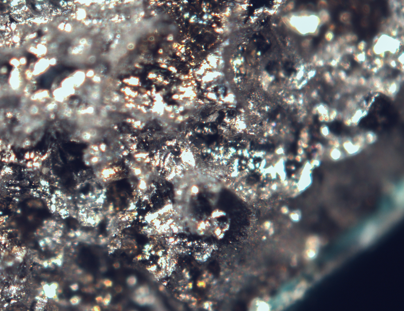
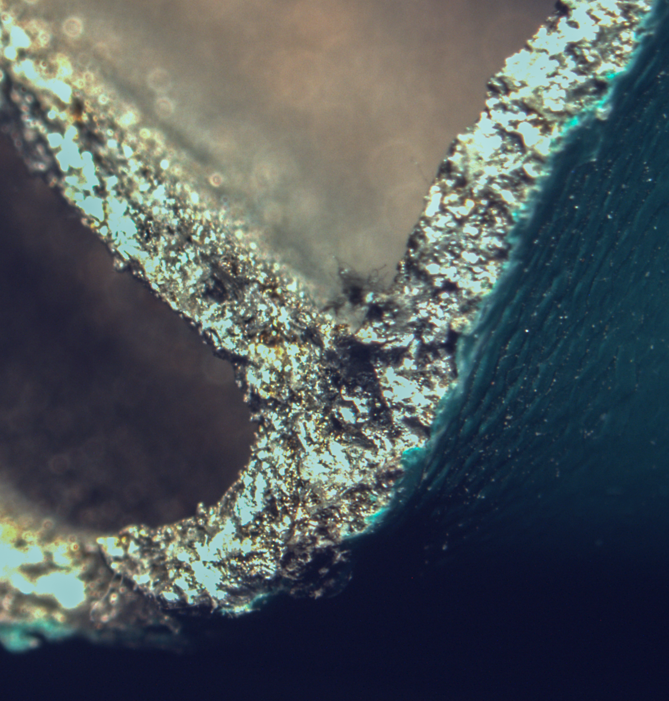
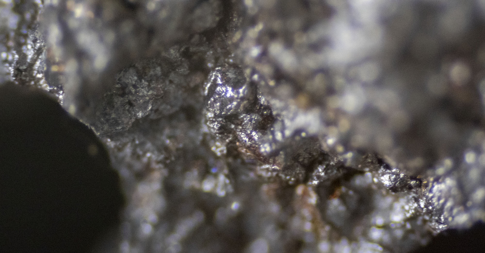
Seeing the part cleave in a near plane make me think about issues with the print. You would have expected to see a lot more deformation of the part during failure if the material were working at full strength throughout the part. There is almost no deformation in the part! This may be the most telling detail here.
Print orientation: In high end engineering for printing, print orientation is a real consideration as it can have an effect on the strength of the part. It may be that these types of parts really do require a specific printing orientation to work optimally. This is where programs like AutoDesk NetFab come in handy.
LPBF 3D printing is too brittle for this application: This may be the devil. Is it just that printed parts are just too brittle to be used in this type of situation? As mentioned before, “unconstrained forces”. Handlebars are unlike other parts of the bike in how they are loaded. I can’t believe that this is the entirety of the problem but is worthy of consideration and additional safety factors.
 Having a sample coupon printed for tensile testing to go along with my parts would make a lot of sense if I were in an environment where that was economical. This would give some information on the run, not so much for the fusion. Still, given the origin of this part, I can’t know if all the parts were printed in the same batch or even on the same day.
I’m including this entire email that I received from a fan. They requested to remain anonymous and any projects they mentioned as they are not the kind of thing that should be discussed openly. This is someone with an incredible resume working with top tier defense and aerospace companies as well as holding a PhD in engineering.
Peter,
As ever I love reading your articles. I love your imagination and insight as much as the execution. I’m really sorry to see you’ve had trouble with your latest DMLS parts.
(unfortunately for you, I’m in a rush, so you get a long letter 😉 )
I wanted to offer a couple of tiny anecdotes of experience if I may- and intended with the greatest of respect. I have worked for a number of Tier 1 aircraft manufacturers, and also for REDACTED (the UK equivalent, and oft partner of REDACTED). With this in mind, you’ll appreciate why I’ll be slightly vague with the precise applications of what I’ll mention.
As you will know more than me, additive manufacturing has been an exciting for many designers, and particularly with the up and coming generation. But as I believe you’ve also touched on, the lack of experience for the youth has also been a bit of their undoing.
Recently, a project for REDACTED saw a great deal of excitement for some of the younger designers, to create something light and un-fabricatable. Me, as the old and cynical knew we’d struggle. The job was for optics components (again, very much your field), but we never managed to get the structures to maintain tolerance post-production. We’d struggled to achieve tolerance spreads anywhere near machined parts, and at good fabrication levels at best. The density spread post production was also cause for concern. Surface finish also isn’t the best in terms of micro inches.
Putting the components through vibration testing and HALT and HASS, again saw a spread of varied results. The engineering is good enough that typically we can see results on tests that align with the modelled predictions (i.e. resonance frequencies). With the DMLS parts, the resonances varied wildly, proving each produced part was “different”. We’re not talking about products produced on cheap Chinese machines, we’re talking £250k Renishaw and Stratasys machines.
My hypothesis was to pin products down to one machine, and one powder batch with a quantified granulometry, but still the parts varied too much for it to be production viable.
With programs marching on, we had to revert back to machined parts. Even investment cast parts that we’ve previously used for harder to machine near-net shapes, was sidelined die to lead-time. All the reasons you look towards a 3D printed parts.
When I look at the elongation on the datasheet that you’ve tabled, I see a line missing. As you know the parts are “grained”. The performance is anisotropic. You need to quantify on a coupon of a matched cross section both along and across the grain. I wouldn’t mind betting you see elongation and a necked sample along the grain, near to your manufacturer quoted material.
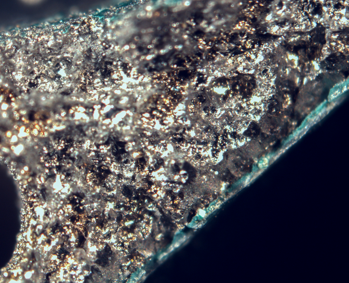
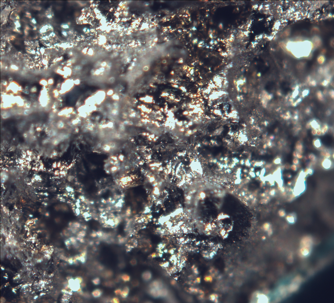
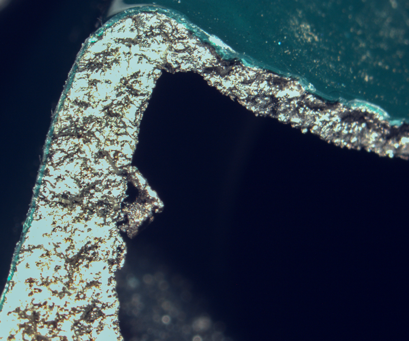
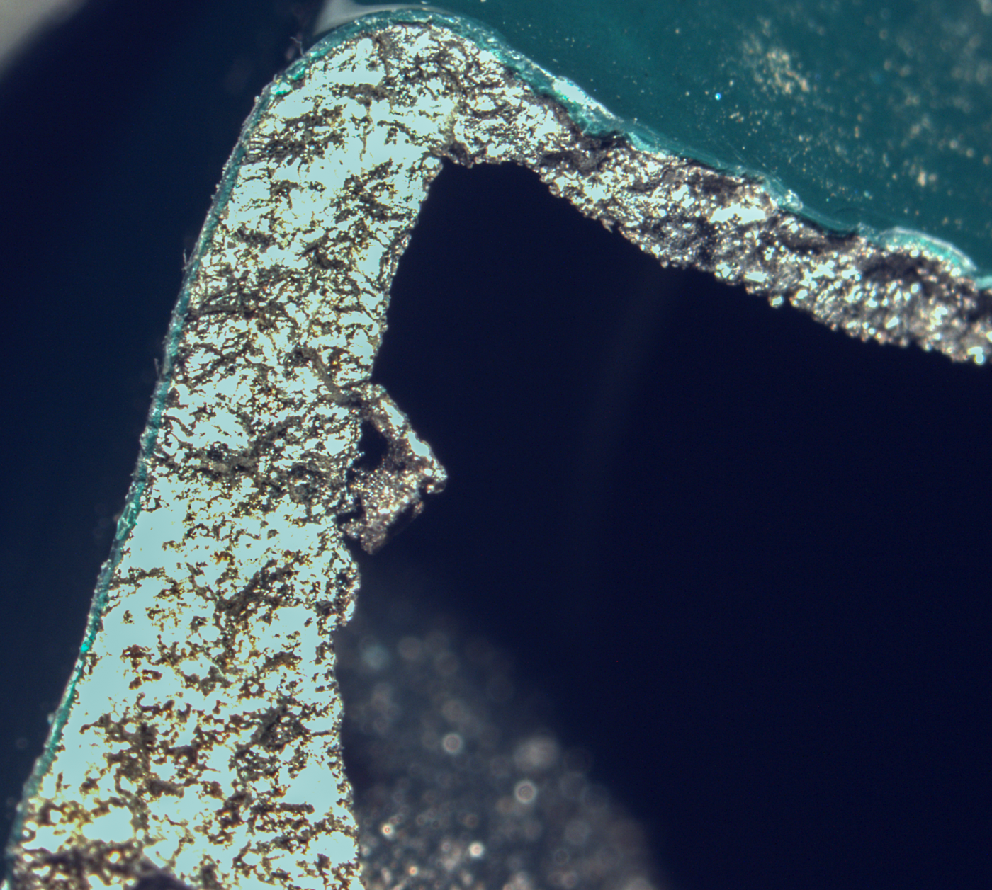
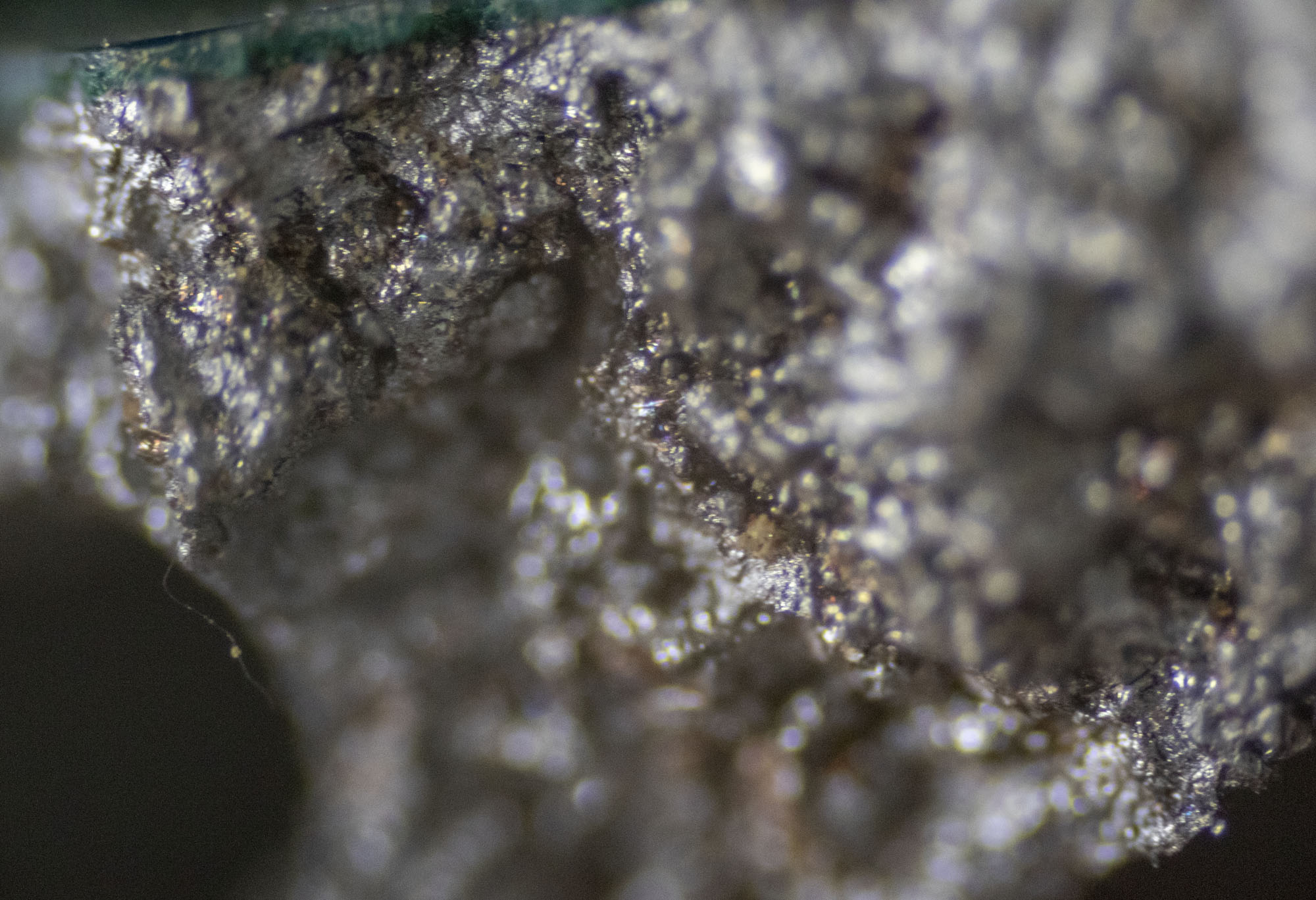
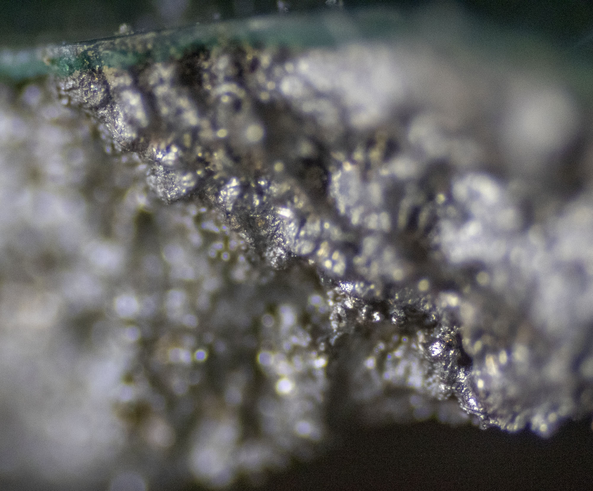
For across the grain, you’ll see order of magnitude reductions, and a fast-fracture surface that looks like the fracture surface of your break.
Obviously we can’t see any fatigue marks /striations/tide-marks at this magnification, but given the speed of the fracture since you built the parts, I don’t think you’re looking at fatigue. I think you’re right, you’re falling foul to micro inclusions and anisotropy.
You’re falling foul to the missing line on the data-sheet.
So, five years on from this last debacle for us, how are we continuing to use the 3D printed stainless a titanium parts?
Well, the 3D printing is useful for production fixtures. 3D printed parts still often need post-machining, particularly if they involve thin sections
We have yet to certify a 3D printed part to fly.
We have used 3D printed Ti extensively for impossible-to-make keyrings and gadgets.
3D printed it is so anisotropic its pretty much unusable in an aircraft operating in all six degrees of freedom (let-alone an REDACTED with superimposed gunfire loading).
Thinking across the industry, I have yet to see a DMLS part that is not utilized in either a non-loaded application, or that is not enclosed or captured within another part, so that the DMLS part can either be retained in the event of failure, or in a situation where failure is either non-critical or cannot be easily detected.
I have seen them used in missile parts, where the part only has to function once.
I really like to see you pushing boundaries Peter.; Sorry that you paid with some flesh on this one.
Best regards and with the greatest of respect,
REDACTED,
PS, I LOVE the stars. Better as a glued insert into your circles though 😉
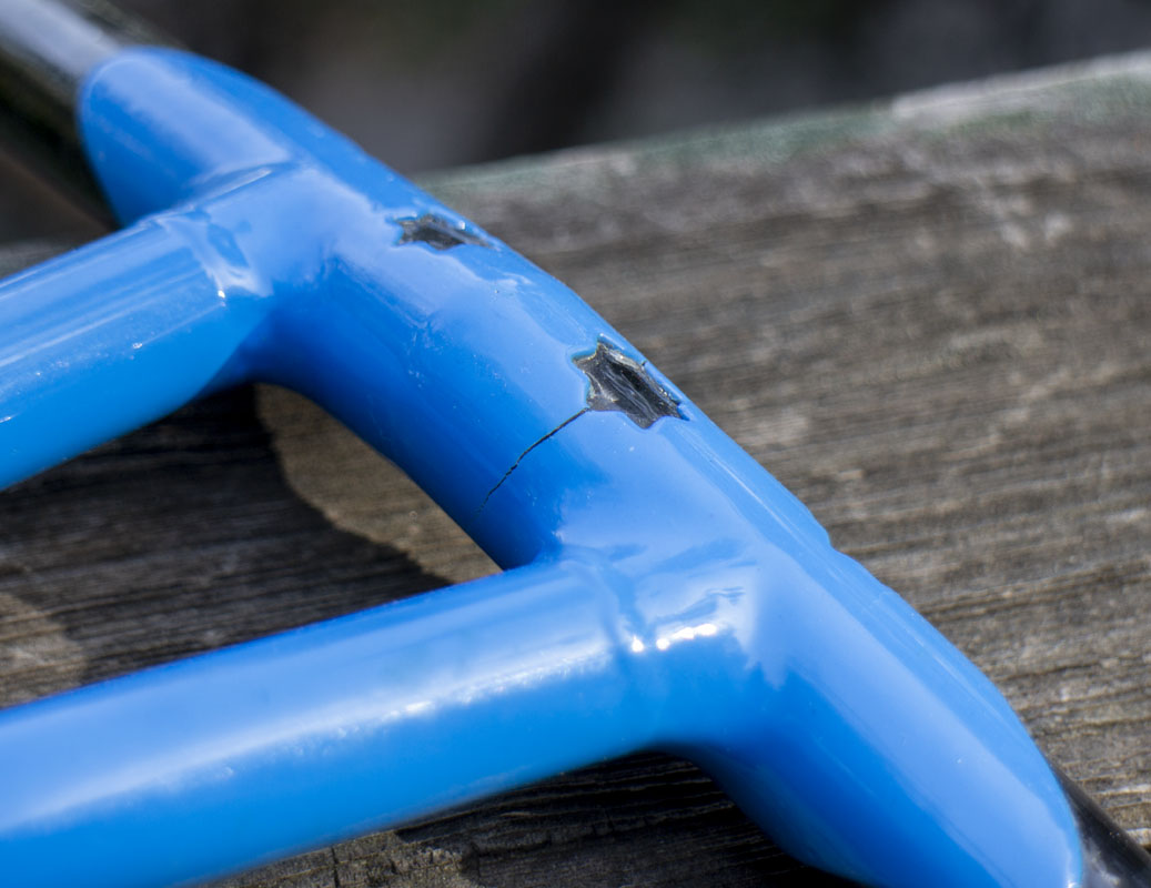
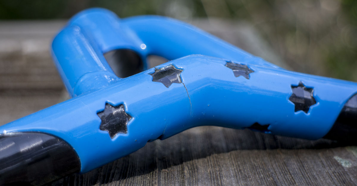
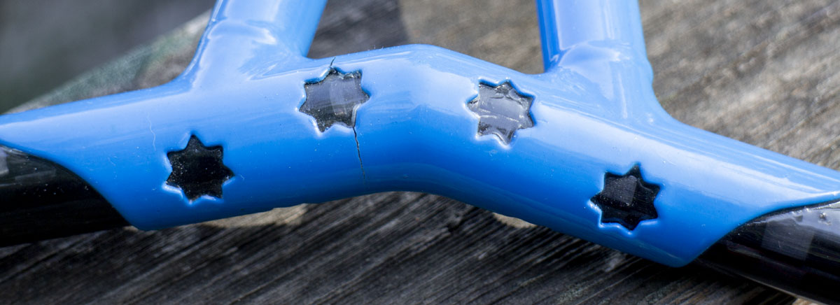
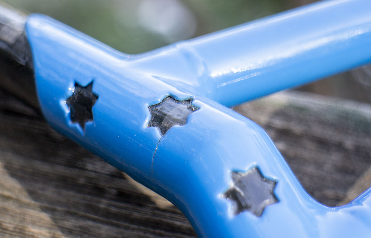
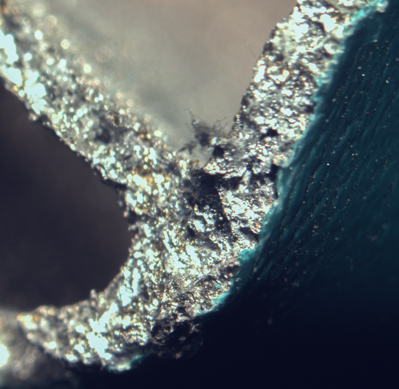
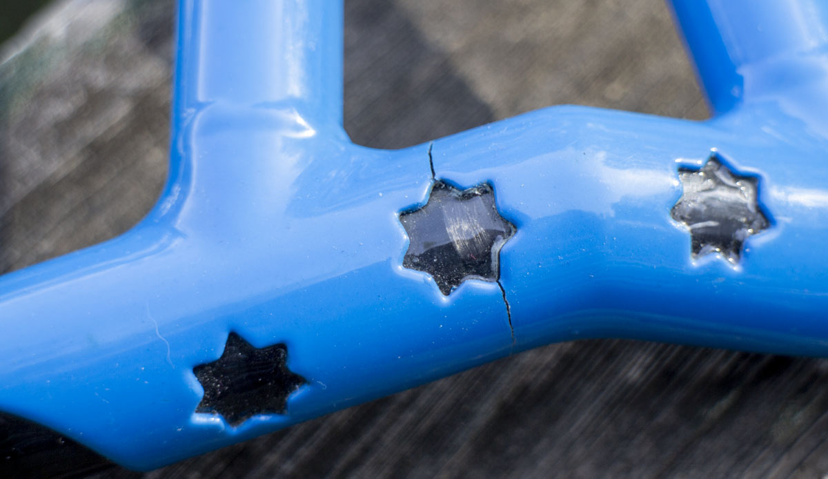
I had tried a 3D printed stem part last year on the 2021 PVD TIE Advanced X1. On that part I had been trying to be a bit looser with my designing methodology and not worry so much as I usually do. I put fancy start cutouts around the boss. I had about a dozen rides on these bars when I noticed this crack when I got to the bottom of my last decent of the ride.
OBVIOUSLY, the decorative star is a massive stress riser. The problem is everything is a stress riser. Which ones do we worry about? This was the test. That part failed, predictably, at one of the stars. The general consensus was that this was an engineering issue. Still, there may have been more to this that was masked by the obvious. Would fabricated steel have failed the same way?
The TIE had star cutouts in the fork crown. Not as absurdly placed but that fork has seen about a thousand miles, and some real smashing on trail without issue. These crown parts are pretty beefy and don’t have a lot of other stress risers. Worthy of note.
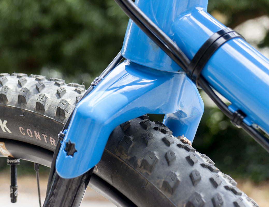
Here is a different situation but the 2020 PVD Supermarine Spitfire has cutouts on it’s fabricated fork crown and fork ends and hasn’t had any issue with lots of very hard smashing.