I’ve made it clear that I’m no electronics expert. This project is challenging my ability to learn at a later stage of life. Still, I’m getting used to all of it and it’s even getting fun.
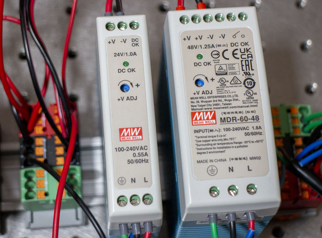
In my research on the CNC control box project, much confusion was made in the vague descriptions of the power systems behind the control and motion components of the system. There’s a huge range of what people are using and what they are doing. Often, it seems that decisions were made poorly or without real consideration. This is what I’ve come up with as the most clear description of the power system;
- 24v DC control and auxiliary voltage
- Build with 24v architecture and adjust CPU voltage as needed.
- DDCS 24v, Mach3 & Mach4 24v, most industrial controllers and PIDs.
- Arduino 9v (5v internal)
- Raspberry Pi 5.1v
- 48v DC motion voltage
- higher voltage if running very large motors.
- 24v or less for very small motors.
- AC VFD option for spindles is nice.
I wish that someone had told me that months ago. That would have saved so much pain.
To have a machine safely stop, emergency stop, power machine off and the safe restart system, we need to plan. This is to ensure, if need be, the machine is made safe as rapidly as possible. If power goes out, the machine will not move when power is unexpectedly restored. Many people skip this but It is important.
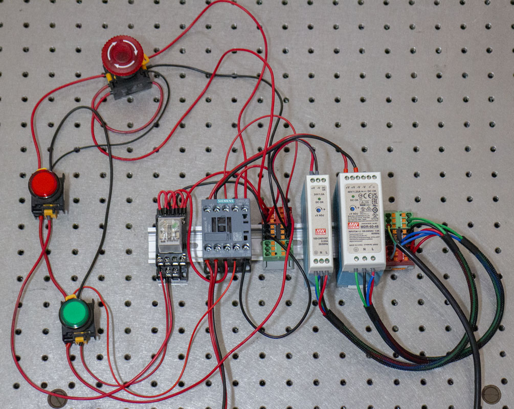
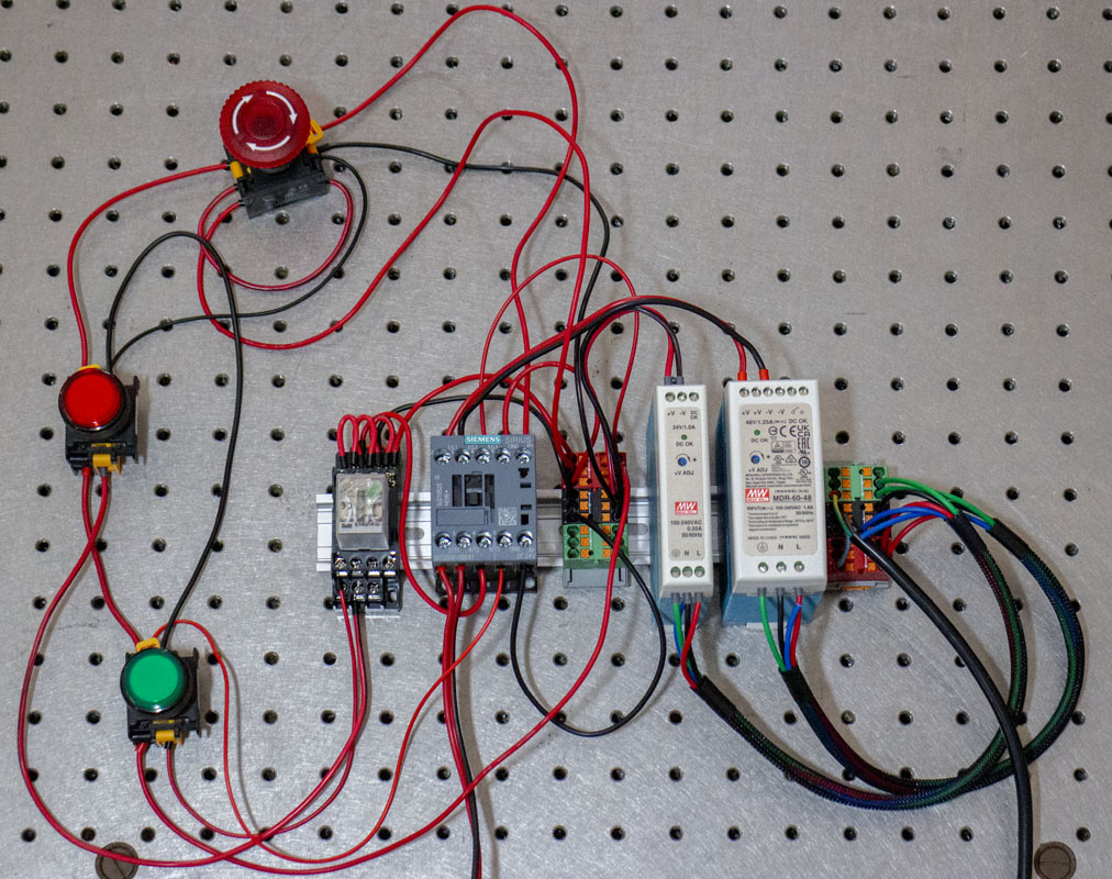
A contactor circuit is used for this with some switches and the control and motion voltages. This design confused me for a long time but I spend some time with it and figured it out. It’s pretty cool. The example below is a little messy as it was just getting the setup validated. In the box it will be nice. I’m still working on the lamp on/off component of the wiring.
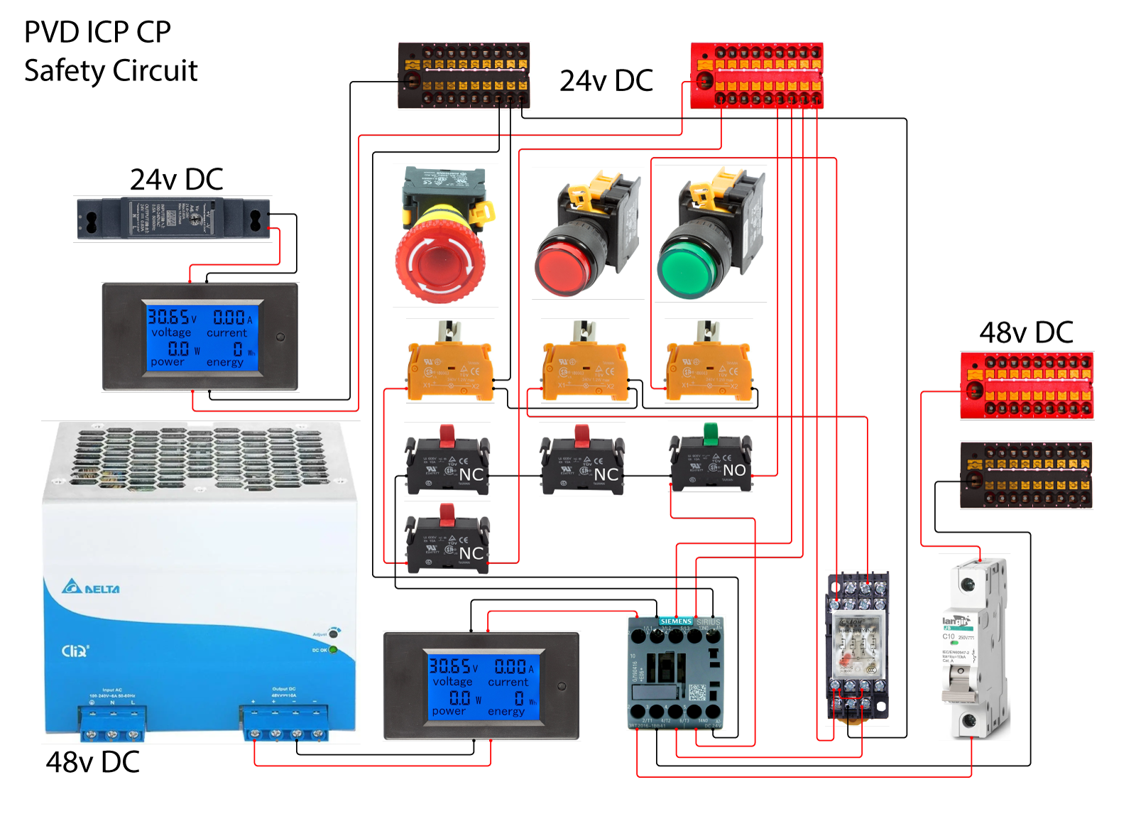
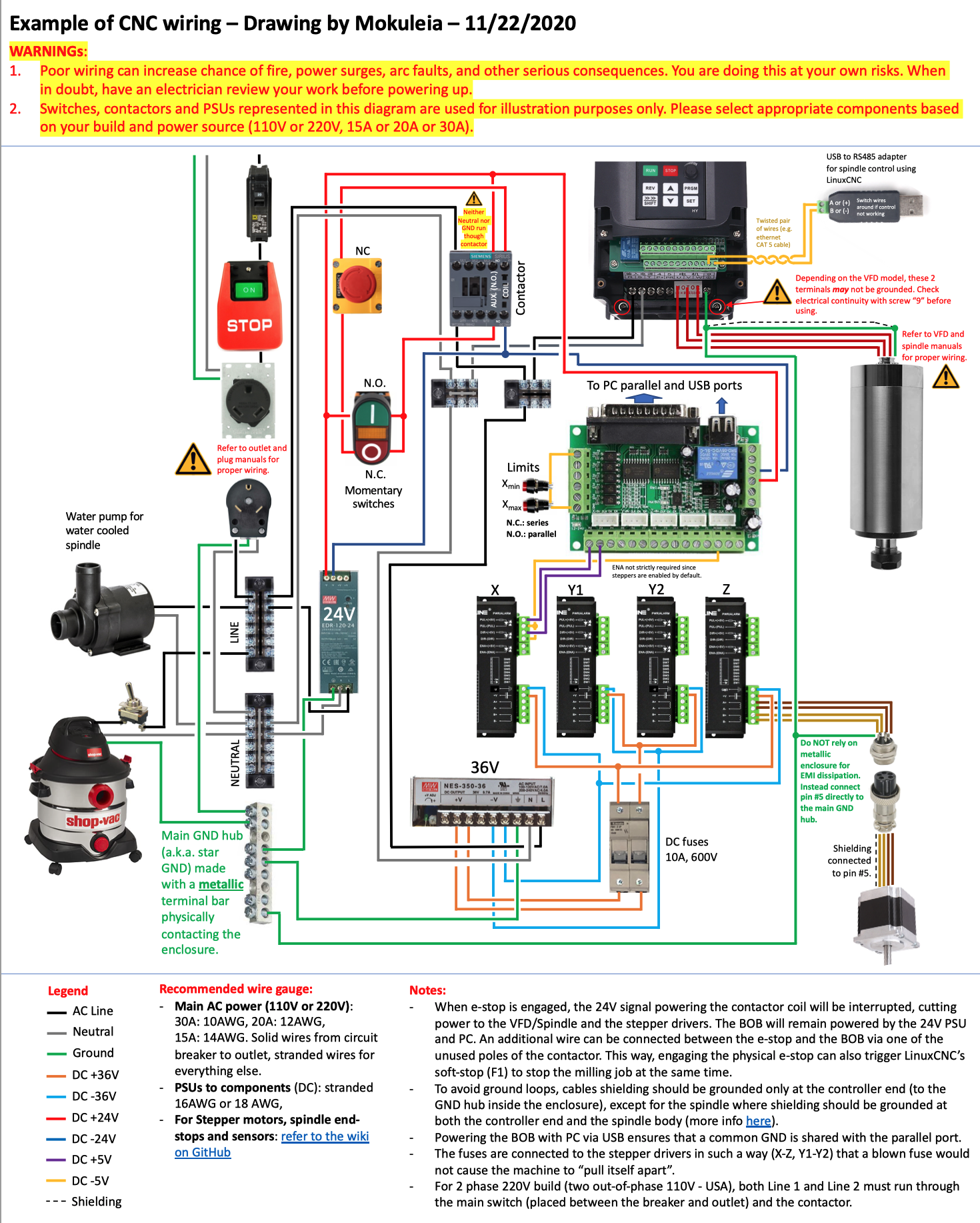
I’m showing the wiring diagram supplied by PrintNC, an open source NC project site. It shows the basic wiring for the contactor and switches. My design will be a bit different than theirs but they are a good resource to draw from.
These are the primary component parts:
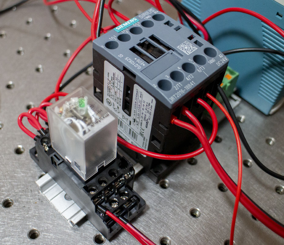
- Siemens 3RT2016-1BB41 CONTACTOR, AC-3, 4KW/400V, 1NO, DC 24V, 3-Pole, SZ S00 Screw Terminal, ($52)
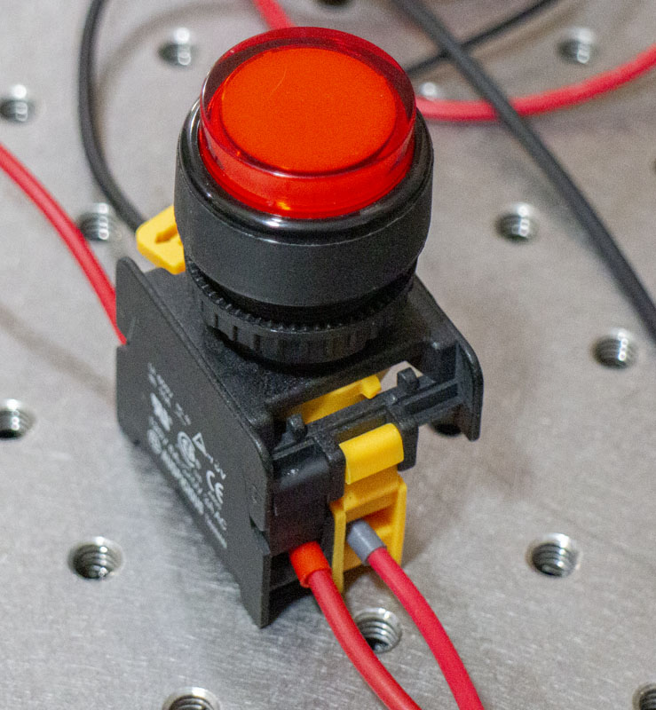
- Auspicious LXL22-1OC, 22mm 1NC Momentary Push Button Switch 24V AC DC LED Illuminated (Red) ($12.95)
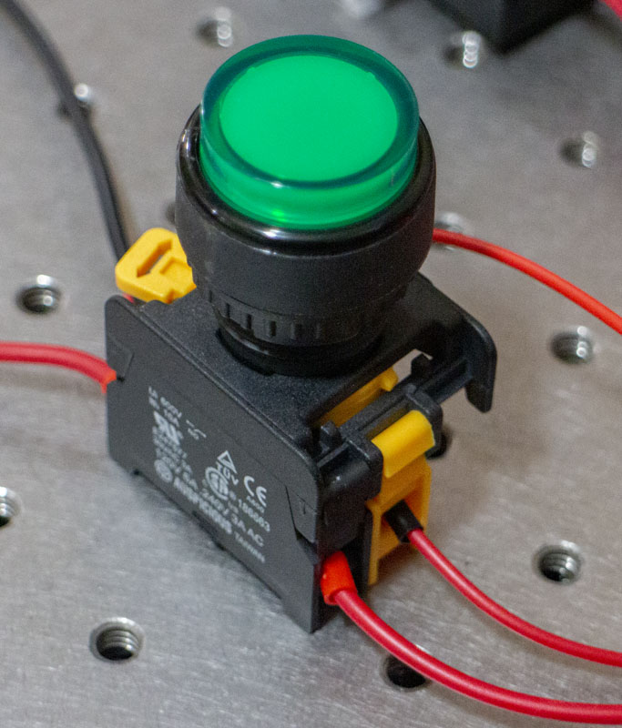
- Auspicious LXL22-1OC, 22mm 1NO Momentary Push Button Switch 24V AC DC LED Illuminated (Green) ($12.95)
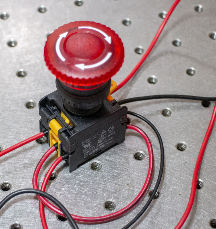
- Auspicious MBL22-1C, 22mm 1NC Emergency Stop Push Button Switch Estop EPO Mushroom Switch 12V DC LED Illuminated ($14.95)
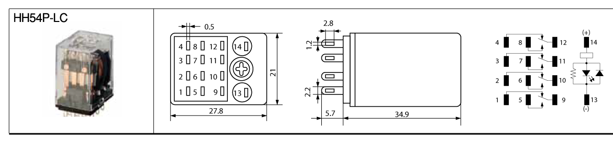
- Fuji Electric HH54P, DC 24V Coil, 14 Pin, 3A, 4PDT, LED ($6.99)
- Omron PYF14A-E 14 Pins Bottom Surface or Track Mounting Socket, DIN (included with relay)
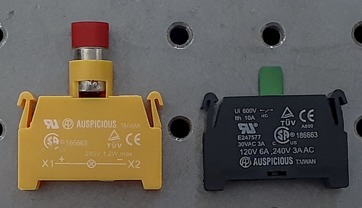
The switches are from Auspicious from Taiwan. This is a huge supplier of switching so parts are common. Here, we can swap out the backs of the switches for different functions.
I was able to have the lamps illuminate correctly within the contactor circuit but the wiring was complex and hard to understand. It was, also, mixed in with the power safety circuit which didn’t make sense to me from a stability sense. So, to get the lamps to function as desired, and clean up the contactor logic, I decided to use a relay to control them. This gives me several options for NO and NC illumination, four circuits in each state. As there are so many options in the relay, I should be able to add even more functionality into the box as it develops.

There are many conditions and understandings for laying out the circuit. For this project, I’ll be guided by these standards:
EN 60204-1 “Safety of machinery – Electrical equipment of machines Part 1: General requirements”,
- Stop Category 0: stopping by immediate removal of power to the machine actuators (i.e. an uncontrolled stop);
EN ISO 13850: Emergency stop functions
- Emergency stop devices of Category 0 (uncontrolled): the arrest of the dangerous organ occurs by immediate removal of power to the machine actuator; – the arrest of the dangerous organ occurs through mechanical disconnection between the hazardous elements and their machine actuator ad, if necessary, breaking.
EN IEC 61800-5-2: standard “Adjustable Speed Electric power drive systems Part 5-2: Safety Requirements – Functional”
- Safe Torque Off (STO): This safety function corresponds to a category 0 stop (uncontrolled stop) in accordance with IEC 60204-1. The power to the motor is safely removed, so that no further movement is possible. In circumstances where external influences are present, additional measures may be necessary to prevent any hazard.