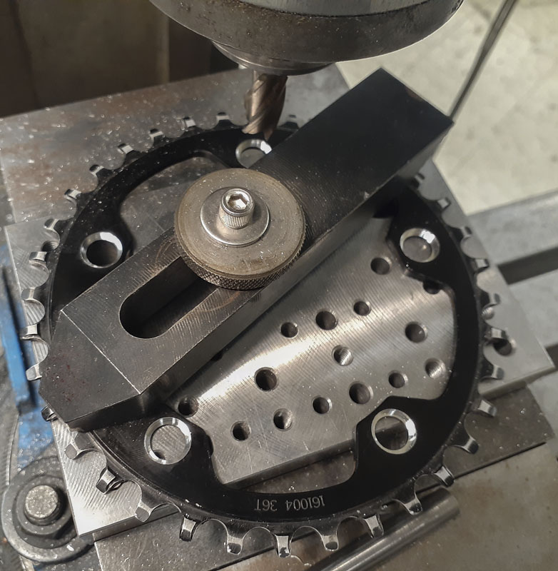
I’ve mentioned using a manual mill with a DRO (digital read-out) as a ghetto CMM (coordinate measuring machine) in the past. Here’s a twisted example of what I’m talking about.
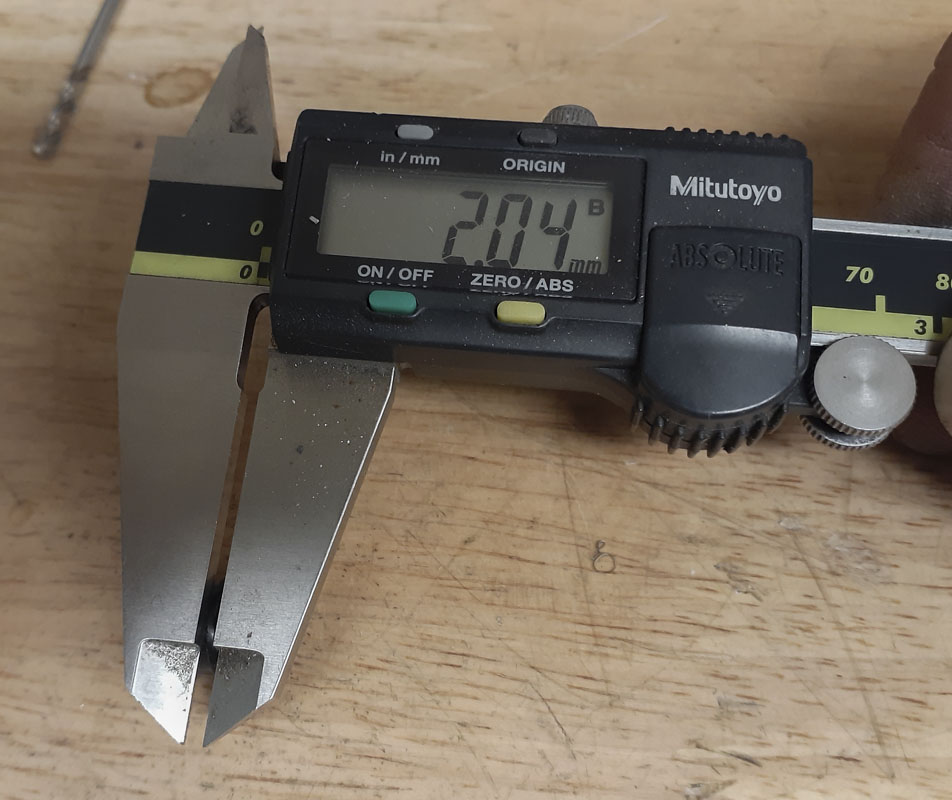
Generally, when I’m talking about the ghetto CMM I’m talking about using the DRO to measure some points on a part so that we can fill in some dimensions in a drawing or model. This gives us the ability to get coordinates of some difficult to arrive at features or references into our drawings.
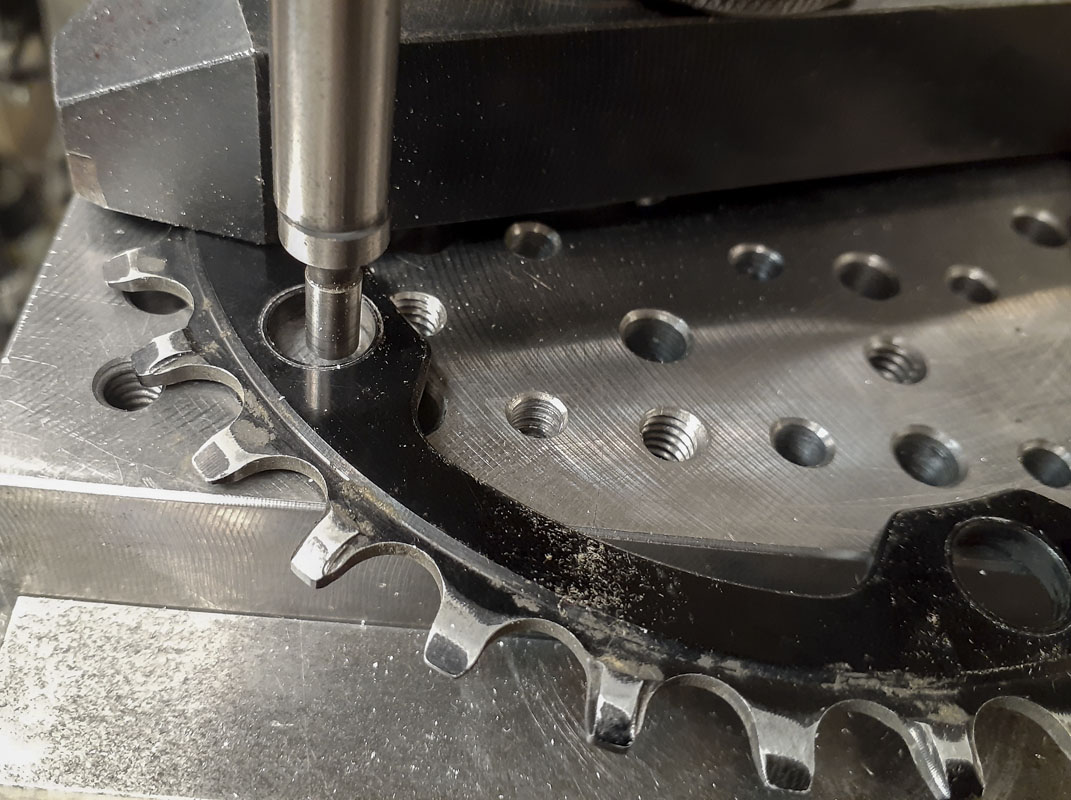
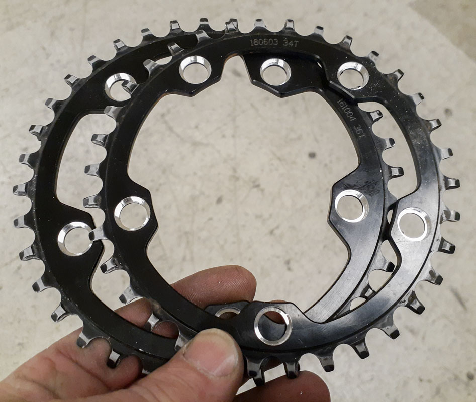
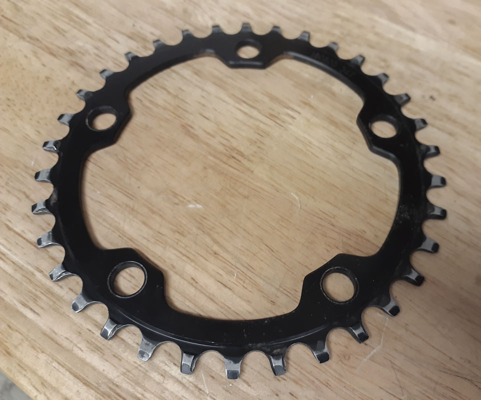
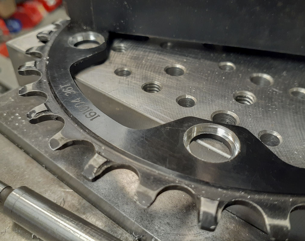
Today, I needed to add some counterbores to a couple of chainrings. Rather than fuss around with awkward location or tedious centering and height setting for 10 holes, to make the job easy, I just clamp the ring down to the vise without regard for position and locate one of the holes. Then, by just getting one ordinate of another hole, I can produce all of the remaining hole coordinates in CAD. Here it is done for 5 holes but it would work exactly the same for 32 holes.
This is a relatively quick way of doing an otherwise shitty job. No fussing, just business. The key is that we are changing our perspective and getting information from the mill rather than only giving it information.
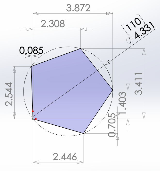
Contrary to what I show here, I should have clamped the part down so that two holes farthest apart are approximately in line with an axis. Then, from the zero hole, measured the small deviation from the axis to align the model. That will give the most precise clocking. Subtle tricks can add precision at orders of magnitude. Pay attention.