This is an important thing for novice modelers and designers to think about. It’s tied up in this example.
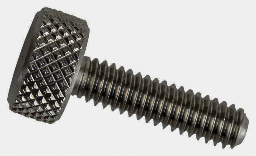
While drawing up a tool I was thinking of making, I chose to give it a knurl as it was a handle and that is what you do. Knurls provide grip. We see them all around us.
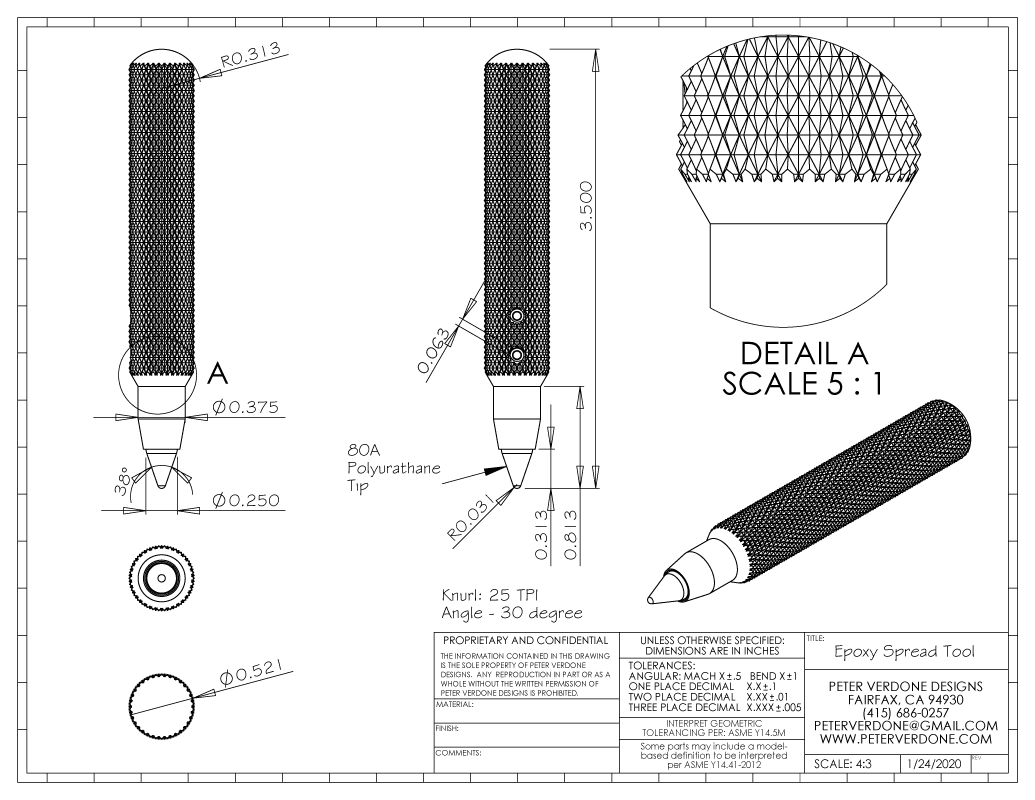
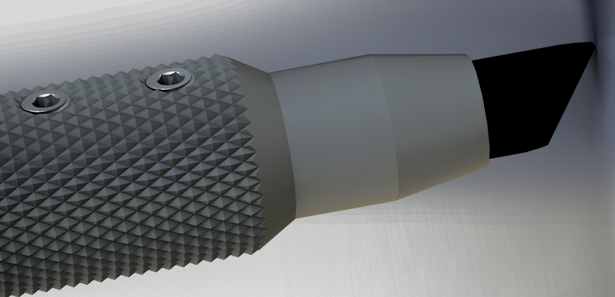
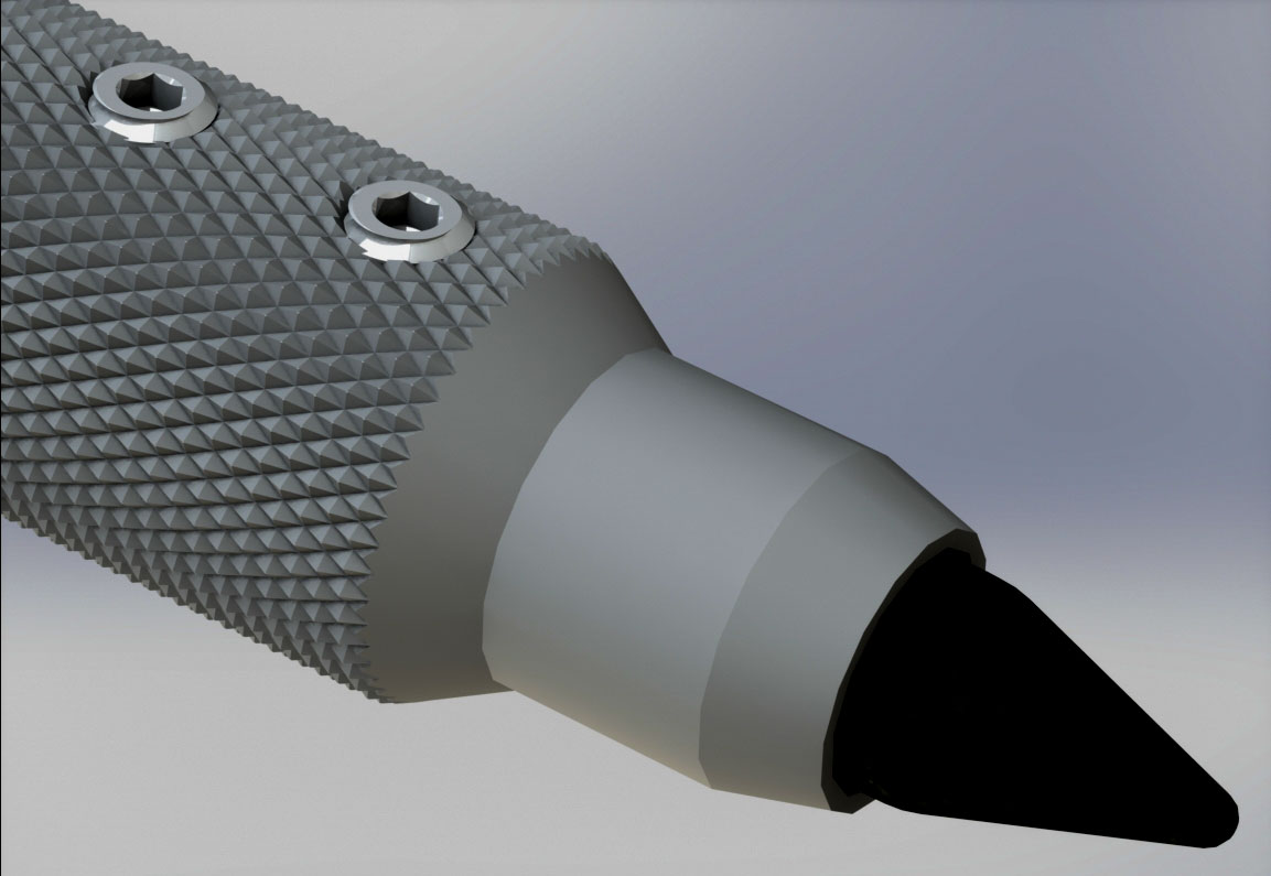
The tool is an aluminum handle with exchangeable polyurethane tip that I’ll use for wiping and cleaning epoxy at the junction of the carbon and steel tubes on my handlebars and forks. Getting right into the seam is tricky without special tools or covering my hands with glue.
 Any time we go into the shop to make even simple things we need to produce a model and a drawing. This process can take less than 10 minutes or months. The key here is that we’ve sat down in a calm environment, we’ve drawn what we want to make, and we’ve mentioned it in a clear and useful way. We always take a few minutes to review our plan and possibly revise it. This is a big deal and can save a lot of time and produce parts that work far better.
We usually don’t model knurls on parts in the computer. The process and the math are relatively basic for the shape. That’s not the issue. It’s two things, really:
- Processing power is limited. While a knurl on a part may seem like a simple radial pattern and mirror, the resulting geometry is very complex on the back end and will shut down the processing of the computer. It will lock the program down solid for a long long time or even crash a computer. This is really brutal stuff full of a huge amount of calculation that require time on even high end modeling computers.
- Knurling is a forming process and the geometry is rather undefined or ‘approximate’ when we start really looking at the details. There are a few shortcuts and rules of thumb that we use, few of which are based on real geometric calculations. Solving those problems is a serious undertaking and would be a nice project for an interested student.
So, most folks will just create a simple cross hatch on the surface or apply a decal to represent the knurl.
I think that it’s important for any designer or engineer to go through the process of modeling ‘the tricky bits’ as often as time permits. I’ve gained a considerable body of knowledge by doing this, especially in bicycle design. Few do this and it’s instantly apparent in discussions with them. “The devil is in the details” and those that skip over the details are rarely introduced to the devil.
There are other reasons why this is important. I have a saying I like to say to folks while we’re in a course of development; “never waste a prototype.” Don’t do that. Prototypes are expensive. We invest a lot of money and time into tooling and testing. You should do as much as you can with each iteration that you actually produce. That means that virtualized prototypes need to be as progressive as possible. The need to be as detailed and as sorted as possible. Problems need to be found before material is ordered and before files are sent to the shop.
We need to be able to communicate our design intent very accurately. The marketing people and investors may need renderings in advance of prototypes. The clearer the images you produce, the less questions they have. If they don’t have doubts, your job moves forward.
In this particular case, knowing that a 25 TPI knurl on the 0.500″ material is too coarse a pitch and a 30 TPI or 35 TPI may be preferred. The tooling in my shop is a garbage 25 TPI knurling wheel. Do I need to get different wheels ordered? What wheels does my job shop have on hand? Are they usable?
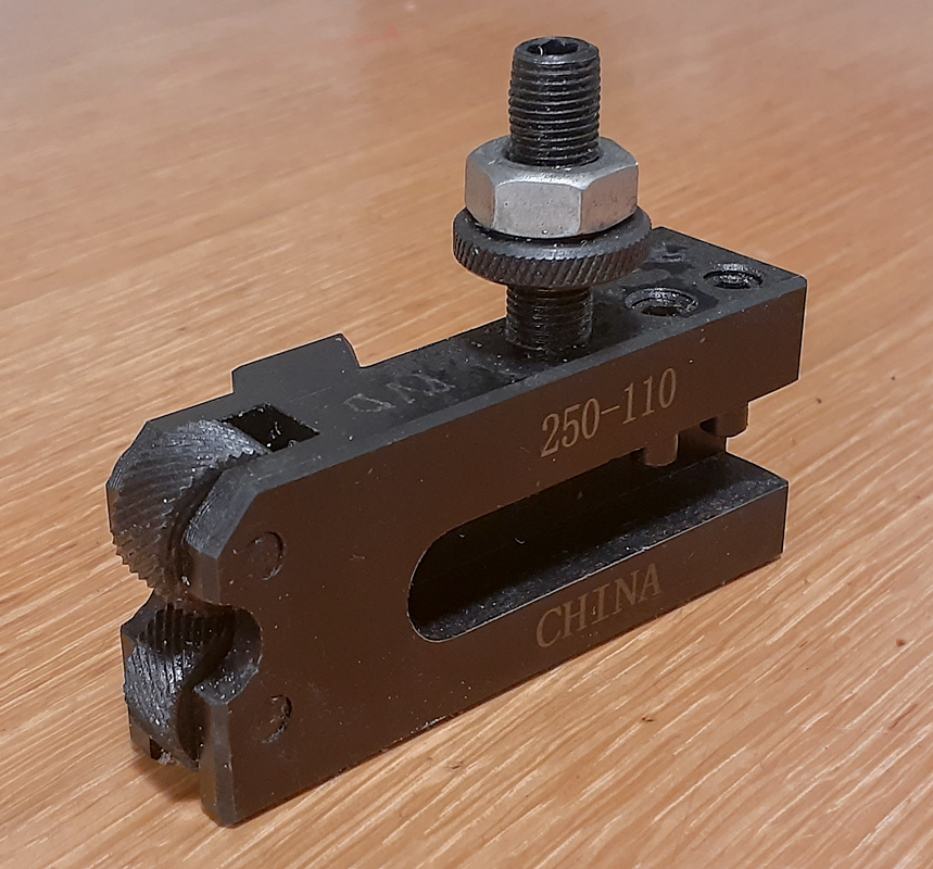
Below is a cheap chinese AXA 25 TPI knurling tool that I have in my shop. I don’t really have another knurl tool around. This influences my choices. It’s a very rickety tool and I have little faith in the sloppy wheels.
Some of the ‘best’ information on knurling can be found on the Dorian Tool website. I say ‘best’ as if you really go through this to try to build an accurate model, you’ll be confused and disappointed. It was not written to be practically used and inspires miscalculations. Reed Machinery has a good pamphlet available also.
I’ll include a few things that I learned to produce the approximate images that you see on this page. I say ‘approximate’ as these are very very close to accurate representations of what the defined knurl will look like and measure. They are not accurate though and some tricks needed to be deployed. Why is this? Knurling is not (traditionally) a cutting process. It is a forming process. Material is pushed from low points to high points (for outside knurls). The shape is produced by the volumetric displacement on a cylinder. Complex stuff given that several variables will change from one case to another….material hardness, knurl pitch, diameter, even machine construction. Wild stuff.
- Knurls are similar to threads…but very different. Generally, threads have a 60 degree cut angle cut on a helix with the cut profile aligned coincident to the axis of the helix. A knurl has a 90 degree (often) cut angle on a 30 degree (generally) helix but in this case, the cut profile is aligned normal to the helix. This is a very complex and important difference.
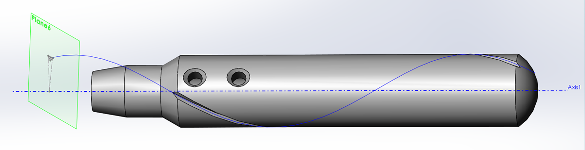
- The pitch for a 0.500″ x 30 degree helix is = ( “Helix Diameter” * pi ) / Tan ( “Helix Angle” ) = (0.500 * 3.14..) / (Tan(30)) = 2.7207″ per revolution. This is really valuable to know. At any point on the helix, the path will be 30 degrees to the plane coincident to the axis. This will come in handy modeling twist drills also.
- The cut for the knurl will be made on a plane normal to the helix but with the point angled toward the axis.
- Don’t use diametrical Pitch! Use TPI. DP is a system that makes a lot of sense. A lot of sources will refer to it. That’s not the problem. Tooling is. By specifying knurls using TPI rather than DP you will have almost twice the choices of useful sizes at times. But that’s not the biggest thing, it’s tooling. Most of the tools that you will find for sale from your suppliers are in TPI. That’s what most folks are going to get easiest. Go with that.
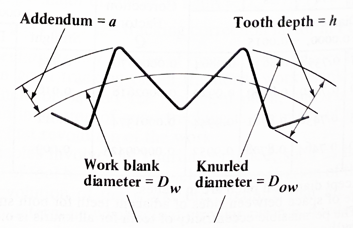
- Correct the work blank diameter to produce an integer value for the number of of knurls on the part diameter.”Theoretical Work Blank Diameter”= .50in
“Helix Angle”= 30
“Normal Pitch”= 25
“Normal Circular Pitch”= 1 / “Normal Pitch”
“Transverse Pitch”= “Normal Pitch” * cos ( “Helix Angle” )
“Transverse Circular Pitch”= “Theoretical Work Blank Diameter” / cos ( “Helix Angle” )
“Theoretical Number of Teeth on Work”= pi * “Theoretical Work Blank Diameter” * “Transverse Pitch”
“Rounded Number of Teeth on Work”= int ( “Theoretical Number of Teeth on Work” )
“Corrected Work Blank Diameter”= “Rounded Number of Teeth on Work” / ( “Transverse Pitch” * pi )
There are a number of little details that will need to be adjusted, but these will get you past the definable and complex parts of the subject.
A real shame here is that the information in Machinary’s Handbook centers almost exclusively around Diametrical Pitch rather than TPI. It may be that times have changed, few folks talk about the math of knurling, we need more selection of knurls, or both but it’s a challenging source also.
An example file is available on the SolidWorks Blog from 2016-08-27. It’s a little different than what I’ve done but it’s better than almost anything else you can refer to.
A guy, PJ, made a calculator for knurls. I haven’t proofed it yet. PJ’s Knurl Calculator.


Knurls can be formed or cut. I have a few videos below of knurls being cut. I show differing cases. It’s interesting. Some artistic licence has been used on the cylindrical knurls but the concept is applied.
Of course, the tool that inspired this post is probably not going to be made. Tools very similar to it are cheap and easy to buy on Amazon for $8.99. Convenience is king and I hate making tools. Still, I learned a lot about design and manufacturing in this model without ever walking into the shop or cutting any material.
