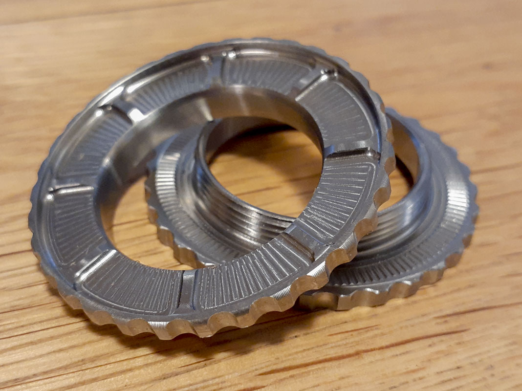
This was a nice gift that showed up last week.
I was talking with Josh Ogle on the phone last week, I can’t remember what started this, I think that I called him about center lock threading. I was talking to him about some nerdy detail for modeling and engineering threads using equation driven formula in the solid modeling environment from ASME B1.13M – 2005(R2020)/ISO 68-1:1998 thread definitions.
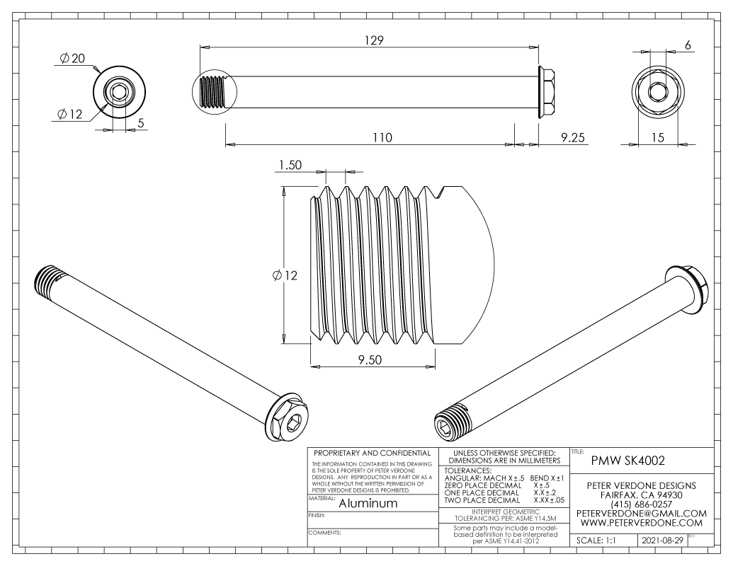
Generally, it’s not a good idea to accurately model threads on a part. It will slow system performance down to a crawl in larger assemblies. If it is needed to see threads for rendering or drawings, it’s a good practice to make them suppressed in a configuration so modeling time is efficient. Thus, it’s rare to need this information. For years I used an approximation as it was simple to toss into a part. I had recently revised my models for frame axles so I had a clear understanding of how they interfaced with my new dropout designs. I found that there was a lot more room for material on the part compared to the older modeling method that I had used, basically, machining in CAD. Sometimes it’s good to think like a machinist. Sometimes it isn’t.
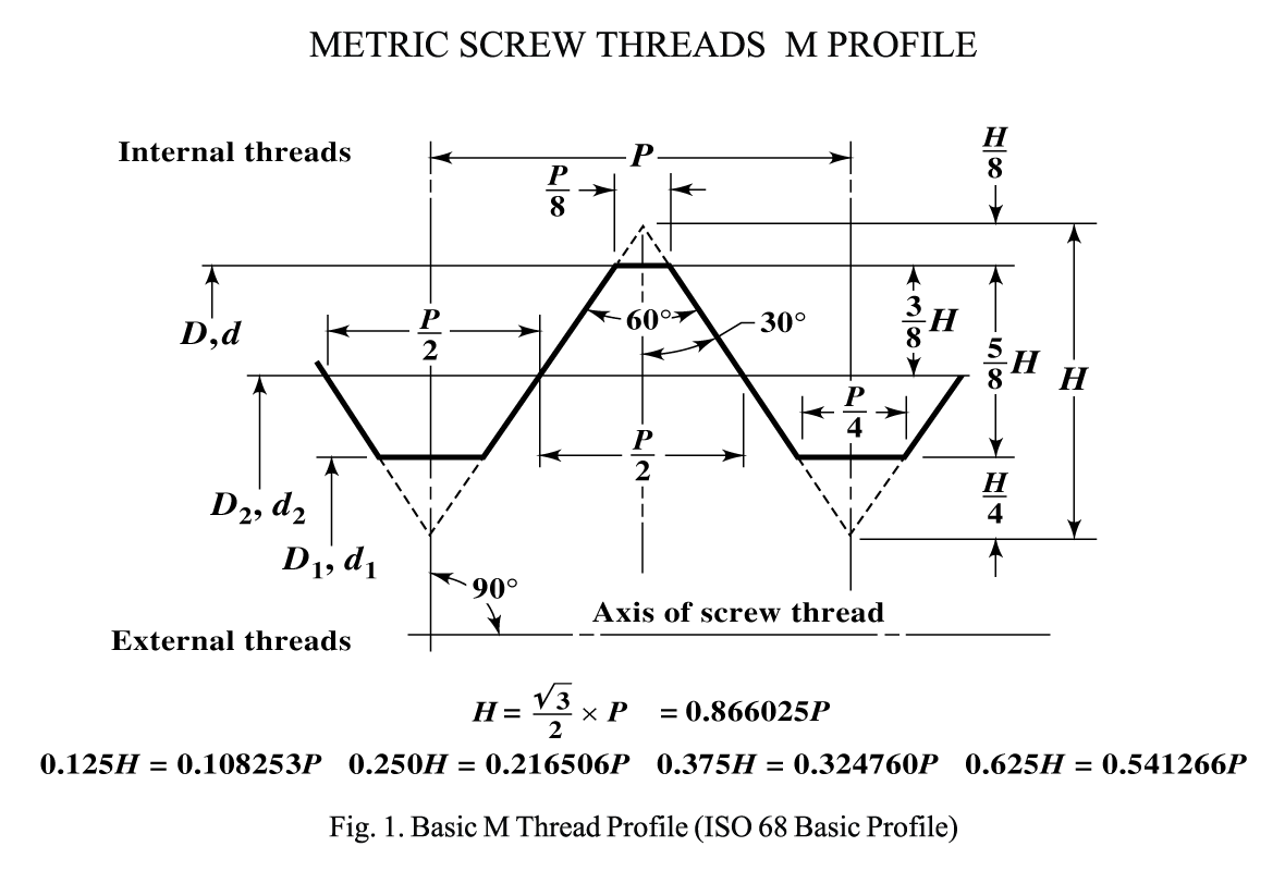
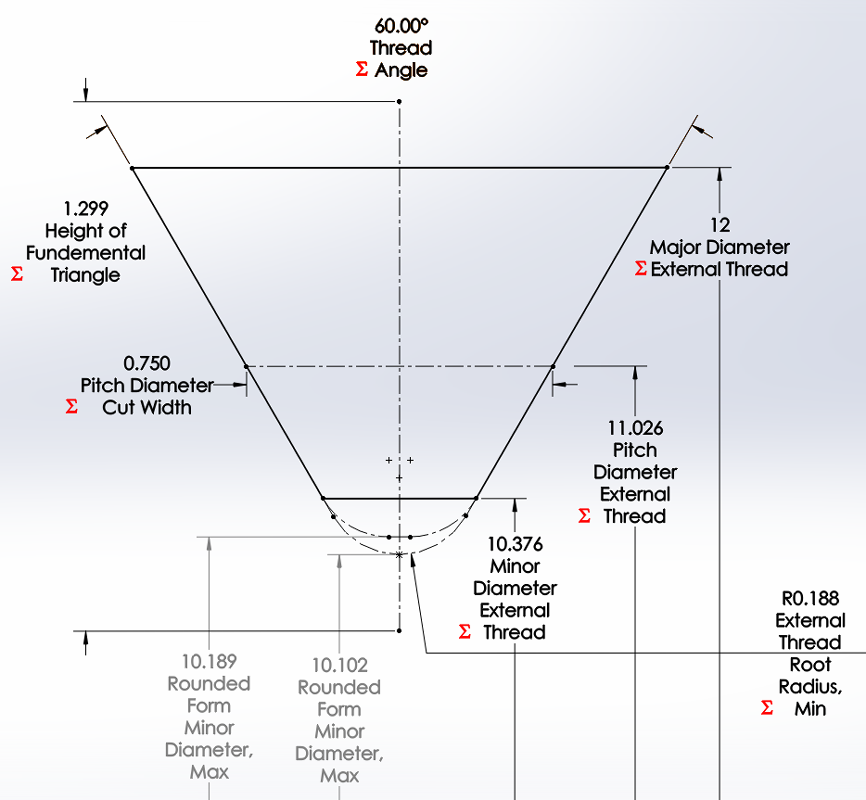
This is, of course, for basic sizing. There are pages and pages more information to ensure proper fit between internal and external threads. Still, this is quite good for general solid modeling.
The point I was making about finding space for more material has to do with flattening the root of the thread. Rather than a full radius at the root, a flattened form gives just a little more room for designs to function. This is a very small amount of material but sometimes anything helps.

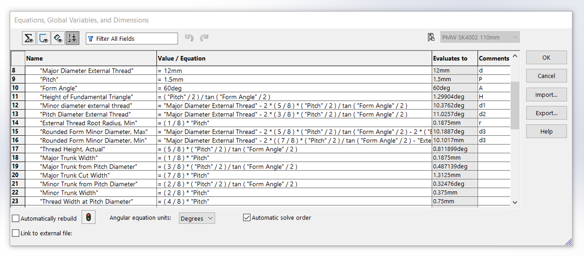
Right away you can see that I’ve replaced some of the formula to be represented in the more general trigonometric form rather than just the 60 degree case. I would love to put more time into doing this as I think that there may be some value there…just not in the case of modeling or producing actual threads. It could really simplify some of the values and precision we arrive at.
Once I got my models all set up to use this method, everything got a lot easier and more precise in my modeling. I won’t get into all of the nuance of the process of modeling threads but there are some pesky issues if you care about accuracy especially depending on the method used. This does a lot to make things easier. Give it a try and let me know what you think.
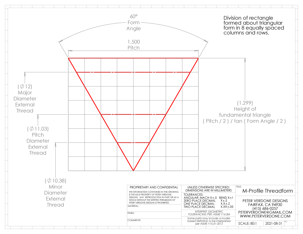
In thinking deeper about this layout, it becomes far more simple than stated. It’s really very elegant. I drew the form over an 8×8 grid. This remains as simple and uses the same 1/8th resolutions regardless of the angle of the thread. It’s really, really cool.
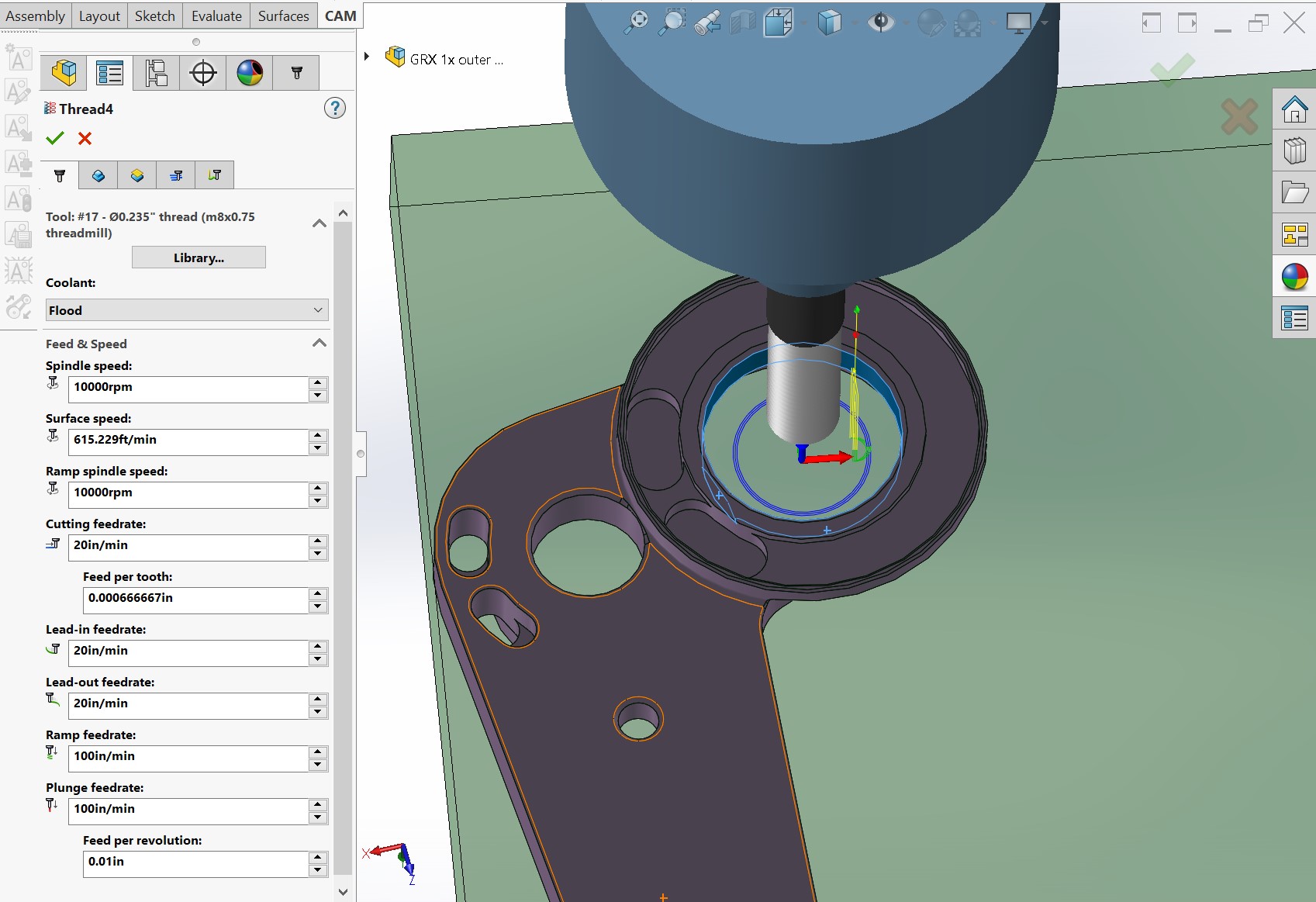
There’s even more to this. When a part goes to machine with threads, it’s common to use macros in the G-Code to do this. This can make it quite hard to really specify the fine bits of the thread form. The thread might be cut on a lathe but it’s become very common to simply mill the threads. That compounds the issues with fine control. I’d love to learn more about this. I’m not an expert and I’d love to hear from some experts on the tricky bits here.
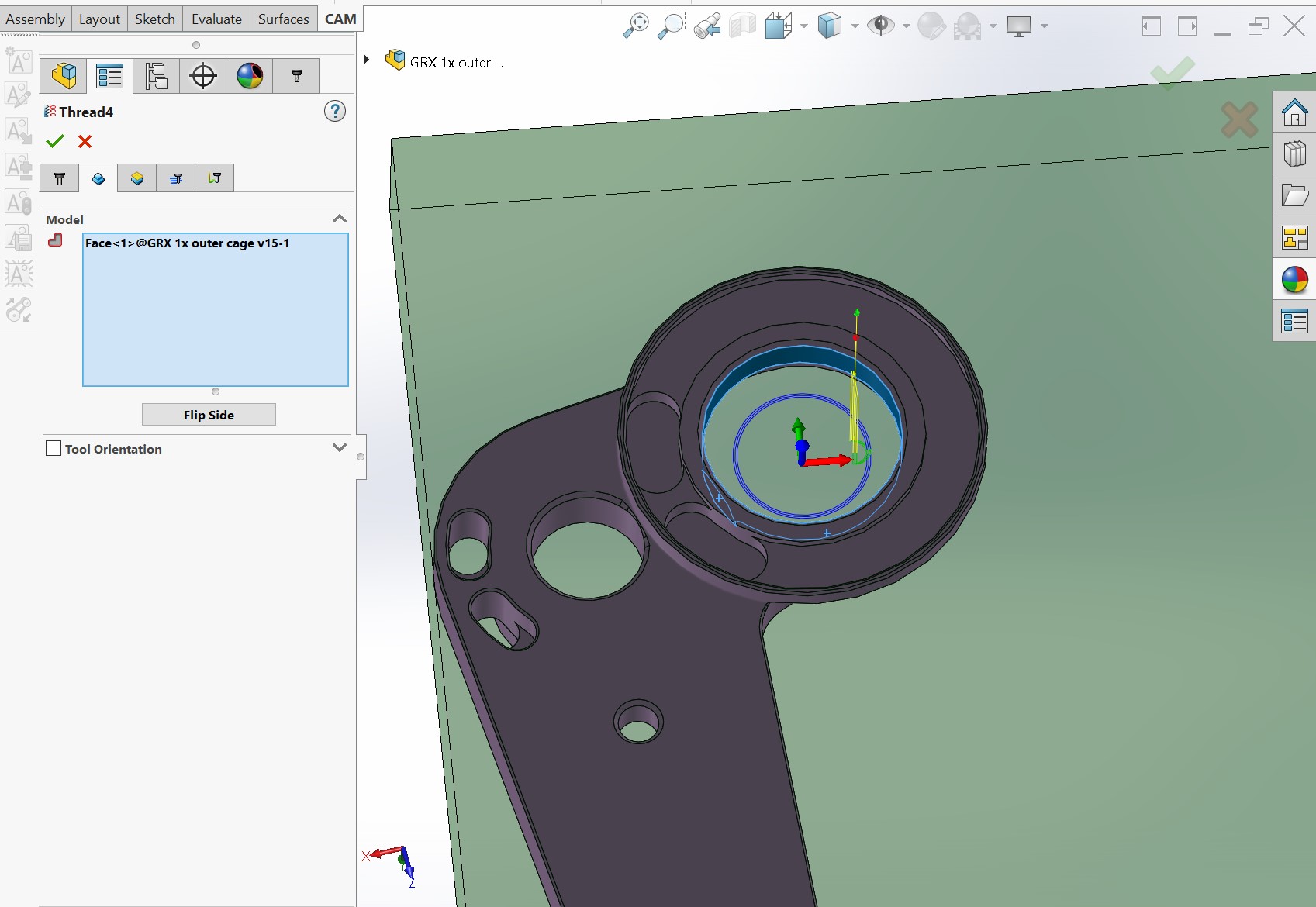
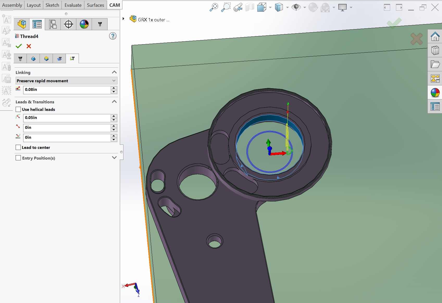
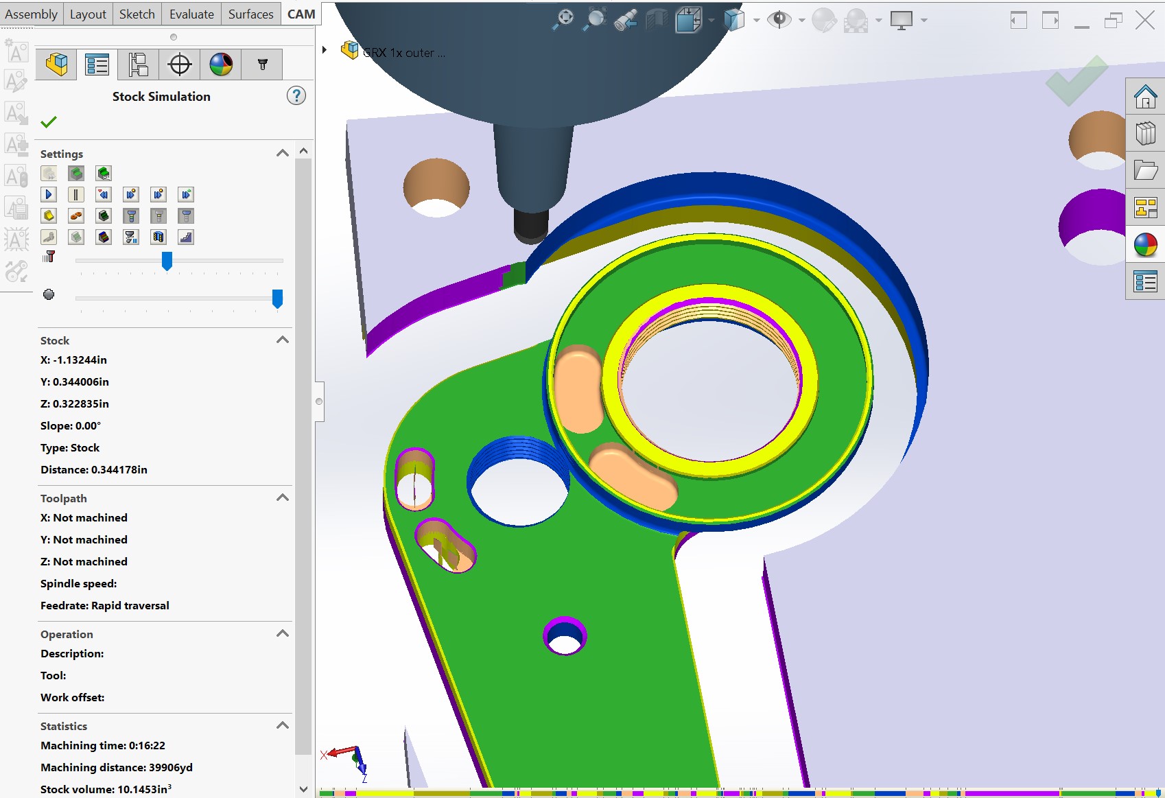
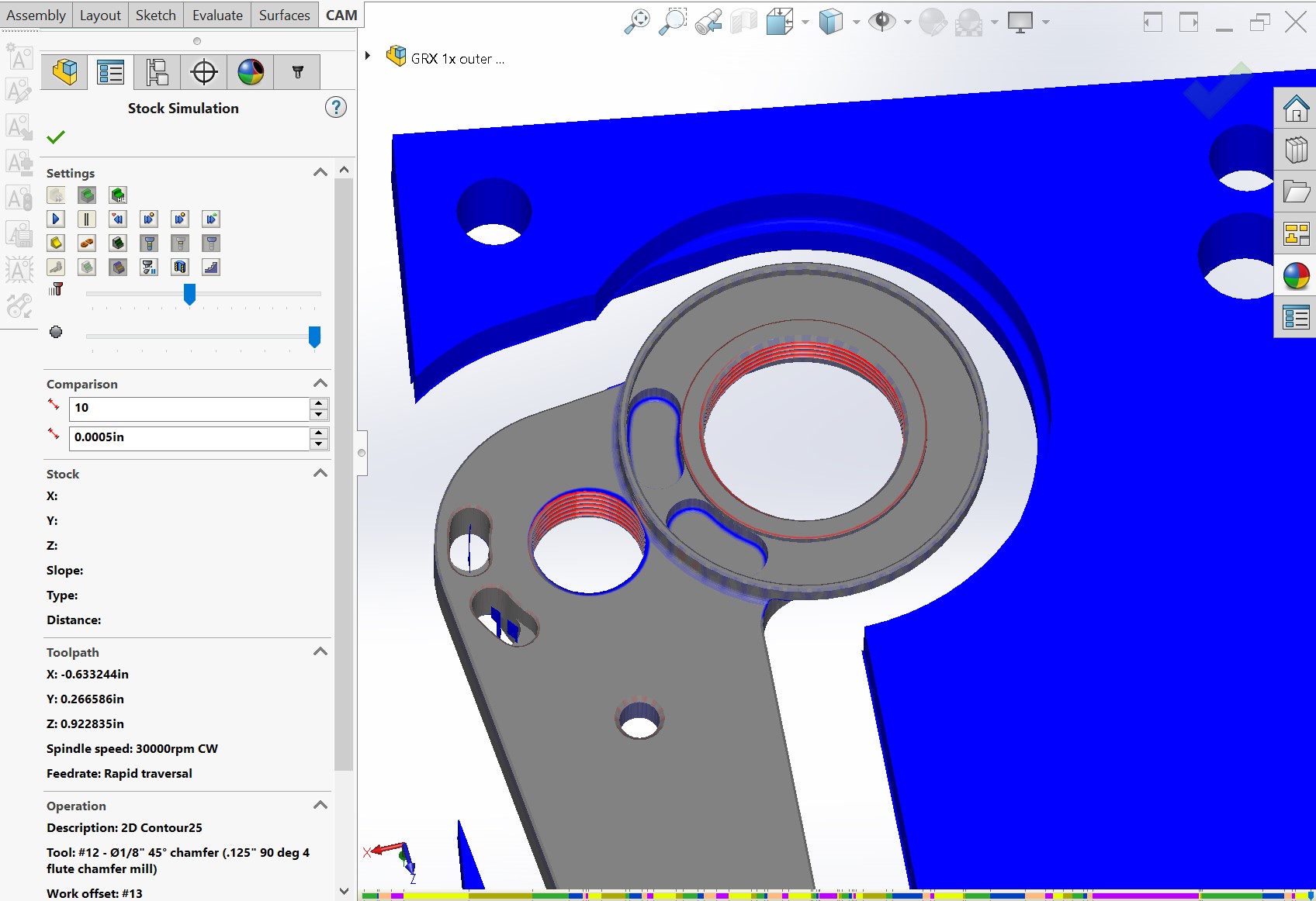
One great thing about the rise of thread milling is that it makes it really simple to locate the thread position and exit relative to the part. In close quarters, this is great news. Josh was kind enough to share some screenshots of HSMWorks that he uses for CAM.


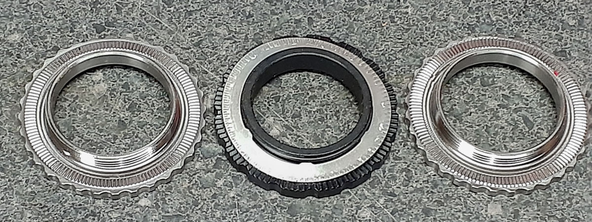
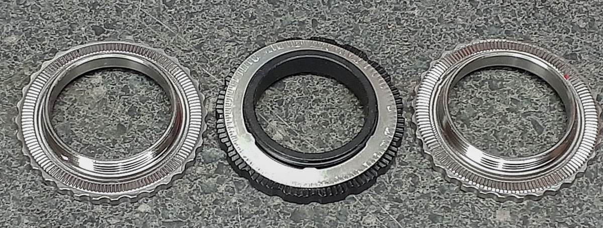
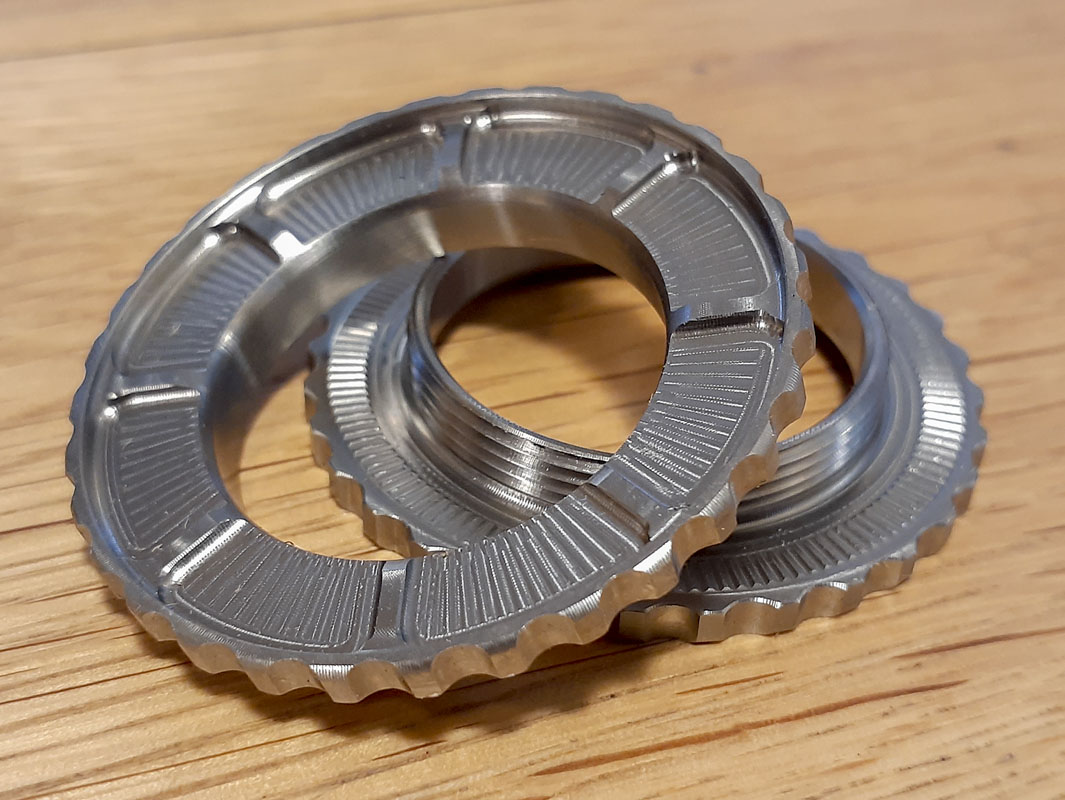
Anyway, Josh insisted on sending me some titanium lock rings for my new TIE Advanced X1. I wasn’t able to refuse.
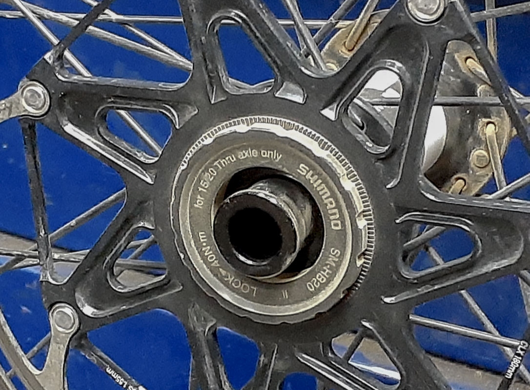
There is an issue in cycling when it comes to lock rings. A hyperglide cassette lock ring uses a different thread than Center Lock. According to legend, Shimano Hyperglide is threaded at 30mm x 1mm thread while Shimano lock Ring threads are cut at M31x23.7tpi thread (1.07mm lead), but DT Centerlock is are M31x1 thread. It could have been very simple but why would anyone at Shimano do that?!
More interesting, Josh needed to know the serration on the rotors that I was using. As it turns out, everyone is using 100x serrations except some SRAM, which uses 144x. Yet another unexplained bullshit lesson in the world of cycle design.

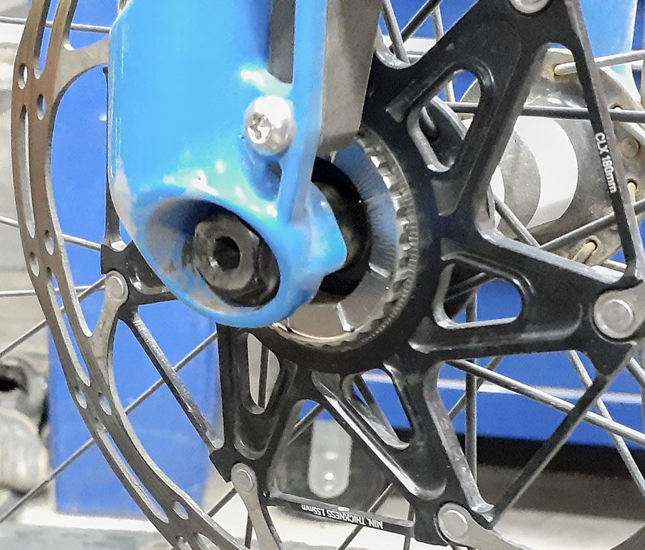
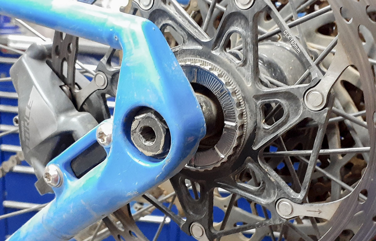
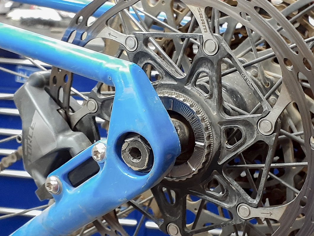
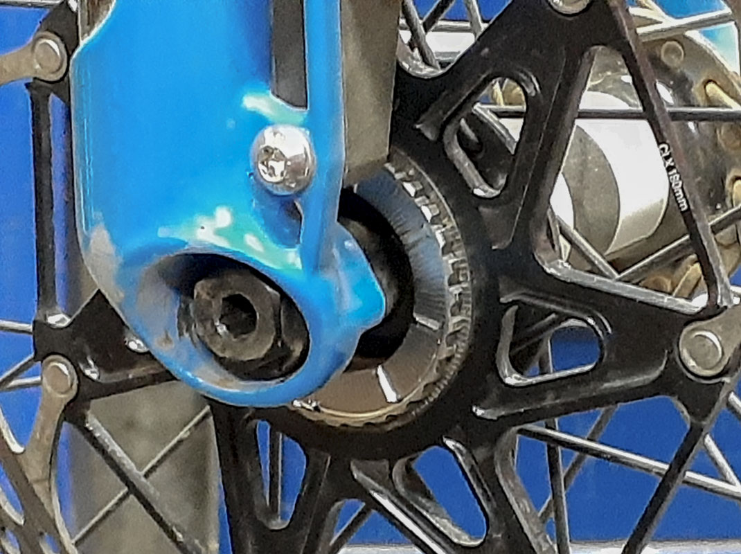
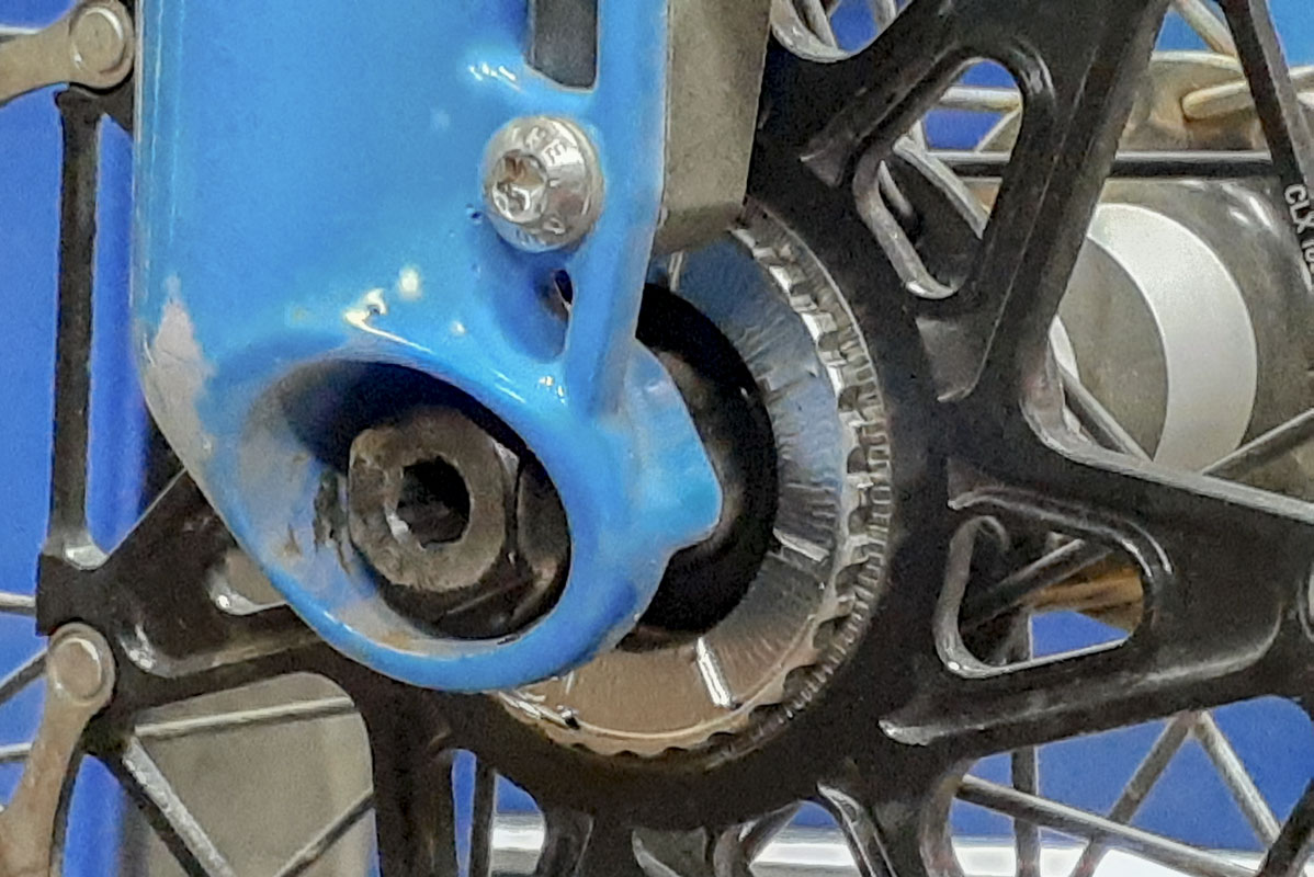
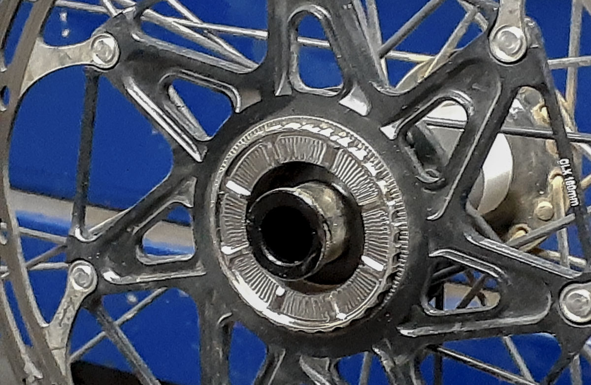
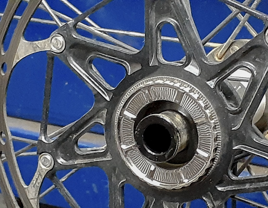
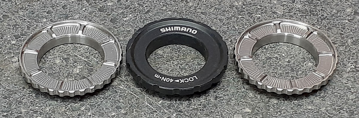
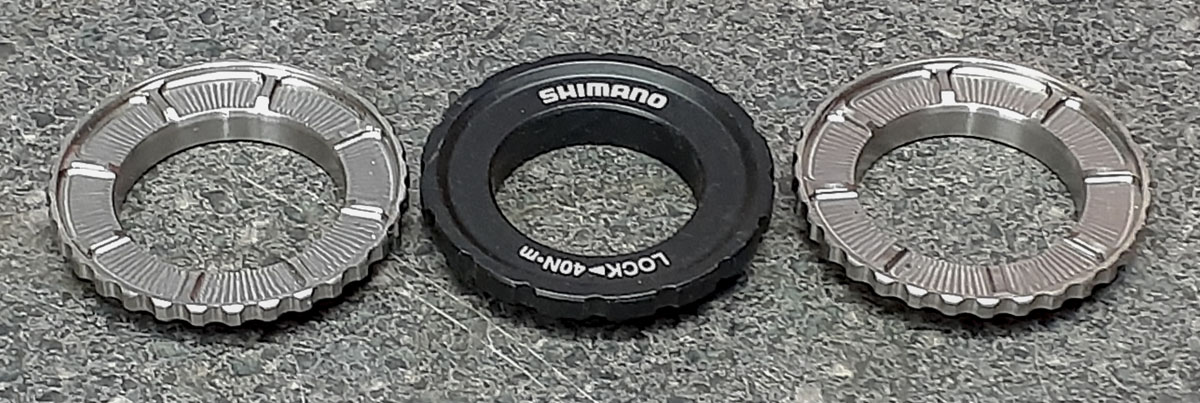
These lock rings do solve an actual problem. The smaller SM-RT96 (Y8CL98090) 44mm 12-ID spline lock rings that are required to clear 140mm flat mount configurations are difficult to use on 12mm axles without modified tooling. The larger, HB-M8010 lock ring (Y2A598030) 44mm 16-OD spline lock ring that I show here are the preferred type in any bike but they generally don’t clear.
Josh’s lock rings are very low profile, still easy enough to work with, and clear the brake parts. He’s assured me that he has done compatibility tests with all major suppliers of forks, hubs, and brake parts. Good stuff.