I think it was 1990 when I built my first set of bicycle wheels.
I was a young man of 20, working at Fat City Cycles in Olive Square in Somerville, Massachusetts. We manufactured very fancy bicycles there. On the side, I had just constructed a fixed gear road frame for use getting around Boston and being a punk. It was basically a 56cm Slim Chance with Columbus SPX tubing and Campagnolo horizontal dropouts that I filed to shape. It was my first ‘custom’ and I had steered clear of making any decisions that required much expertise. I’d go on to test many of my prototype fork designs in that frame, one eventually going into production.
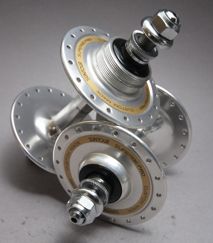
I had sourced a full Suntour Supurbe Pro Track group and front brake caliper from the road group for putting the bike together. Thus, I had a pair of those gorgeous high flanged hubs in my hand along with a pair of Mavic MA40 rims. The problem was that I had never built a bicycle wheel.
My experience working with bicycles at the time was pretty thin and I was working on building skills. I had been working on my bicycles and motorcycles but I hadn’t gotten this deep with bicycle mechanics. My buddy at work, Gary Mathis, was giving me some guidance while I went through learning the wheel construction technique. He wasn’t doing much aside from pointing me toward the work I needed to do. I was clueless.
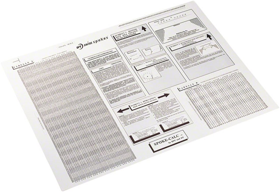
I had already sized the spokes with a Spoke-Calc wall chart and calculation. I had the spokes and aluminum nipples in hand. After work one day, it was time to lace up the wheels and tension the spokes. An hour when by. Another hour. I was lost. I was frustrated. I felt like I had ruined everything.
I went to Gary and asked if he would bail me out of hot water and fix the wheels. In a move of raw wisdom and integrity, Gary refused. It was my mess. I needed to dig deep and get out of it myself. He was right. I went back to the stand, started over, and knocked out two sets of wheels. The Rubicon had been crossed. I did it. Those wheels were my first. They worked great. I called them “The wheels of steel” because of the solid high flanges…and the abuse they saw.
Since, I’ve built every one of my wheels in all sorts of conditions and situations. I’ve built motorcycle wheels and trailer wheels. I’ve casually consulted and tested for several hub, rim, and wheel manufacturers. I know more things now.
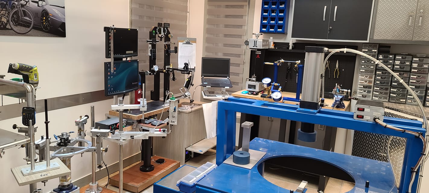
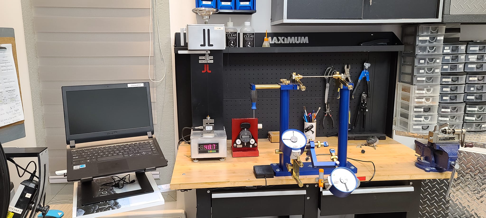
Just like building bicycle frames, wheels need special tools. Sure, you can get by with very few tools but when you have great tools you can do exceptional things with ease.
In the last 32 years, I’ve seen a lot of amazing work and tools from a lot of very good wheelbuilders. The memory that stands out the most was watching a wheelbuilding race during a winter party when I was living in Durango. There were maybe 5 people in the race. Of note what John Tomac’s mechanic and this one other guy who’s name is lost to time. Seeing the speed of all these guys was pretty awesome but this one guy was so sick. When the bell went off, he picked up the hub, slammed all of the spokes into the holes, then picked up the rim and went around the rim in order threading the spokes into nipples. It was so slick and fast. I couldn’t do that.
Anyway, years have gone by and we can now learn from experts without being in the same room with them. When it comes to wheels, nobody can compare to Steven Harris from Saint-Hyacinthe, Quebec. I’ve never met Steven in person but I’ve watched his work over time on Facebook. His tools and shop are absolutely insane. This guy is the grandmaster of wheels. I learned of Steven after seeing his insane spoke tension meter calibration tool. It sets the actual spoke and nipple to be used and applies a precise load to it so that the calibrated measures can be made true to the actual parts used. The rest of his tools, I learned, were similarly stellar. Reviewing his work is a must for any wheel builder.
I’m also friends with local wheel building celebrity, Steven Gravenites. Gravy has been around forever and built wheels for more former and current professional racers than I can imagine.
Anyway, I do some special lacing for rear hub brake wheels. This conforms to the specification as laid out by Shimano and many others. Getting these laced is a real pain in the ass given that I’m not doing it every day. Sometimes the wheels go together easy. Sometimes it’s a real struggle.
![]()
What would help is having a wheel lacing fixture so that I can hold the hub and rim in precise alignment while figuring out exactly where I want each spoke to lay. I’d then know right away if spokes were where they really should be.
This is not the kind of tool that the average wheelbuilder might have. It’s for when the shop is going to another level. I’ve wanted one for years. Stepping up is the hard part.
I sat down to draw this up while on a trip and killing time. I came up with a pretty ingenious system for centering the parts. As I was detailing the design, I showed Ronen what I was up to. He said it wasn’t simple. It wasn’t elegant. He killed my baby right in front of me. I started over. I did some cool stuff and showed him again. Again, he killed my baby. I went at it again. This time, my baby wasn’t able to be killed. The baby was strong. The design was formed.
I spent a bit more time doing the detailing and the math. It seems like it’s ready for public now.
The goal was:
-
- Easy to make
- Easy to use
- Precise
- Rigid
- Light
- Easy to stow away when not in use
- Build wheels from 12″ to 36″
- Rims from 19mm to 50mm wide
- Hubs up to 197mm+ wide
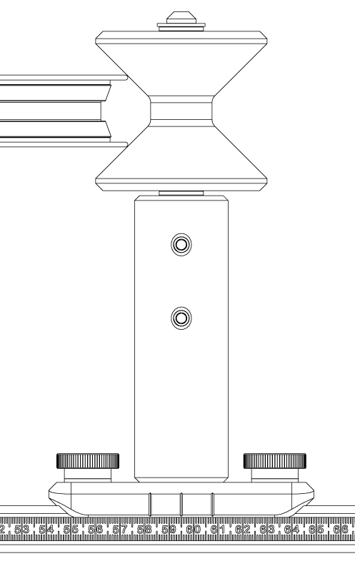
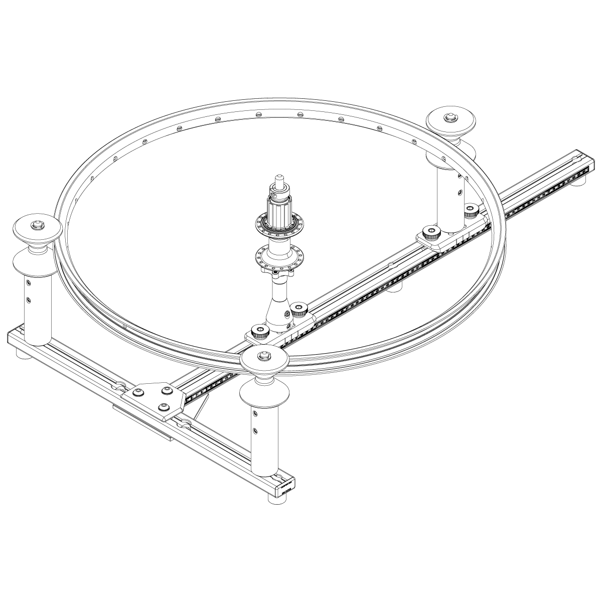
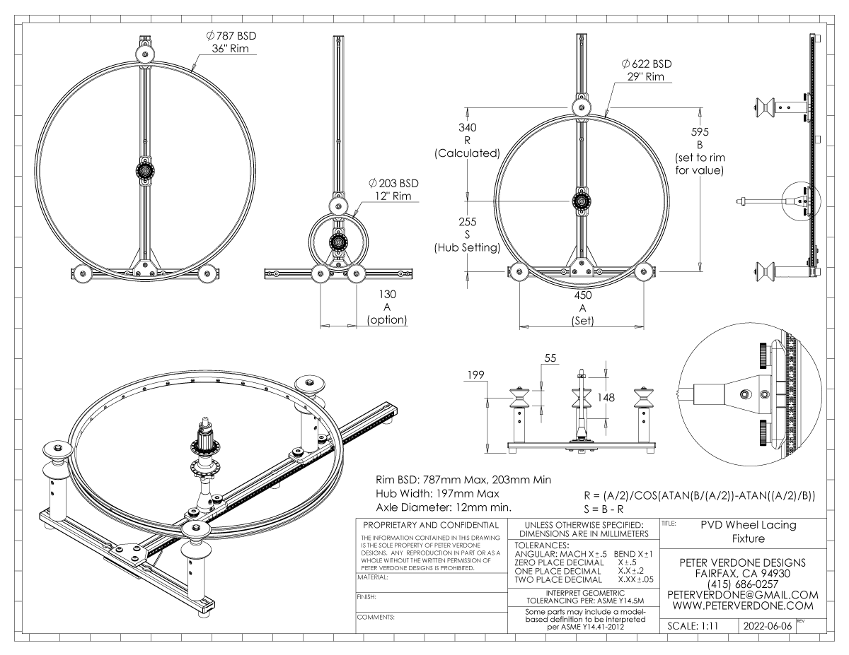
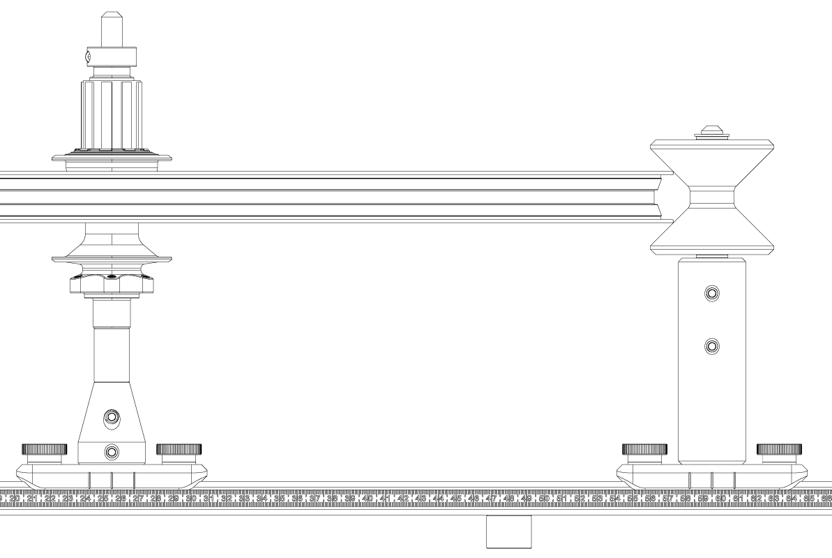
The design uses two fixed reverse cones at a determined distance apart on a t-rail. A third reversed cone slides down on a central scaled track to hold the rim securely with very light pressure. A reading is taken from the rail and from that the a measured setting for the hub pin location is calculated. It’s a very elegant solution and not one that I’ve seen used for other fixtures. This is different.
The math that I originally developed.
R = (A/2)/COS(ATAN(B/(A/2))-ATAN((A/2)/B))
S = B – R
I had used a technique that I developed for complex trigonometric solutions. It worked out fine. Still, it was pointed out by Sam Atkinson in a discussion that more basic algebra could have been used to solve the problem, yielding a ‘simpler’ formula. I love when folks share back.
S = ( B^2 – (A/2)^2 ) / ( 2*B )
The hub can also be placed with simple direct measured placement if the calculation is unbearable. Because the hub and rim are always aligned along one axis, it just takes a centering adjustment along that one axis rather than other designs which require several axis adjustments.
As being compact is a factor, spokes do not drop through holes to a fully hanging state. They could be if the construction was made a bit taller. That depends on user discretion. I can get by with this slight inconvenience for the tool taking up less storage space.
I may make this to be even lower and disregard building 36″ wheels with it. That would reduce the size significantly. I wanted to ensure most cases to ensure that nothing was overlooked.
To produce an extremely precise 90 degree alignment of the profiles, the parts are held in position on a fixturing welding table in just the right alignment. They are clamped in place and tightened. Then pin holes are drilled the last 25% and pinned in 8 places so they can not shift…ever. This is yet another powerful use of the weld tables.
Construction materials are 8020 1575B profile and bracket, 1.5″ 6061 round bar, and 2.75″ Delrin rod, 12mm SS shaft and a bunch of other fasteners. I haven’t priced it all out but $250 in materials should be reasonable for a tool like this.