
I’ve decided to share a couple of my dimensioning templates for others to use. I’m thinking that this can move some others forward in an easy way.
One of the more powerful components within BikeCAD Pro are the templates that a user is able to construct, save, and share. Custom title blocks, notes, paint schemes, riders, displays, etc. All kinds of valuable shortcuts. While some folks make good use of this, many do not and it shows in their work.
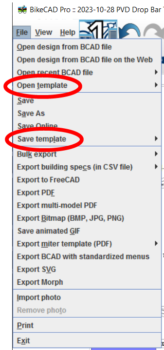
I use ‘dimension’ templates very often to save my current methodologies for looking at the underlying design for what will become a bike.
There are three primary types of dimension schemes that most users might use.
- Setup Print – This type of dimensioning will describe the whole bike as it sits and is used. It will include the contact points and handling geometry that tell the reader the story of the ride. We understand the saddle, stem and handlebar geometry within the design. Dropper and fork travel and settings should be understood. We see what rims and tires the design is based around. It’s the whole picture, as detailed as is manageable. If the bike is a hardtail with a suspension fork, the bike will be shown with the fork sagged the prescribed amount. If the bike is full suspension, it is most often shown fully topped out in the travel.
- Setup Prints (Option) – In this case, the main setup print will be broken into two different prints. One for the rider fit information and the other for handling and other details about the bike. This produces significant clarity and makes it easier for a fitter/user to look at just the part they may be focusing on.
- Frame Print – This describes the frame, isolated from the system and mating parts. Some of the angles and lengths can be seen that we can use to transfer into a setup print for proper evaluation. This is what most folks are used to seeing in advertising copy. Generally, we can understand what design philosophy (if any) the designer used to produce the design. The frame print has little value other than giving information that will go into a setup print.
- Build Print – This tells the builder how to construct the frame in the shop. Lengths of tubes and cut angles. Tube diameters, jig settings, etc. This has very little use outside of the workshop and should not be shared.
Within the frame building world, we see a lot of the frame/build prints. Most of them very poorly produced and seriously lacking in understanding, detail, or clarity. These should be made much better considering how simple they are when done right. Then a template can be saved for later use.
What I’m most concerned about is the near total lack of setup prints shown in discussions, media, and communications. I get emails all the time from builders (new and old) that are working on something. When I ask for their setup print, it’s like I’m speaking a foreign language. Most often, I get a very bad build print. This isn’t good. It tells me a lot about the level of understanding that the builder has and how poorly their ‘development’ program works.
A custom bicycle frame HAS TO BE produced from a setup print. The whole point is that the frame is tailored to the rider and their use. Without knowing the locations of the touch points, tire and wheel sizes, expected stem and handlebar, etc, how can decisions be made that will optimize the frame design? It’s just not possible.
A field showing the date MUST be included in the print. A design will take several iterations over a period of time. It can get be confusing or impossible to know what is the current version without a date or revision tracking system in place. Nobody wants to have tubes cut for the old design.
Considerable testing and development will go into a setup print. We use it to prototype changes and purchases. It’s our guiding light. A real development process starts here and can lead to very valuable understanding for both the rider and designer. It’s what lead to most of my advanced development concepts.
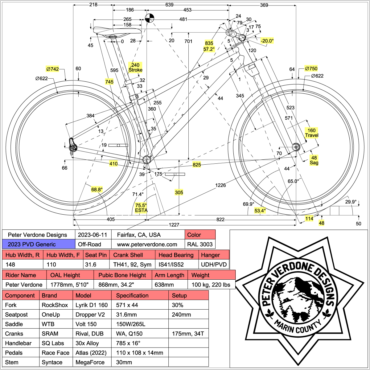
Where every frame starts, the setup print! Here, a typical hardtail mountain bike.
The road bike with drop bars get’s a little trickier due to the shape of the bars and the several particular hand holds. Still, we can get a reasonable facsimile.
(I wish some of the more passionate road folks would put some time into proper road bike dimensioning)
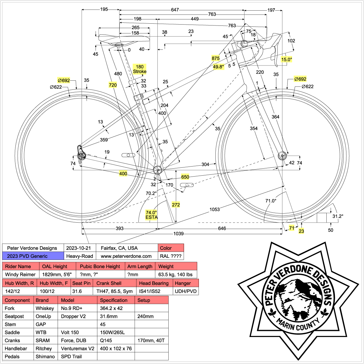
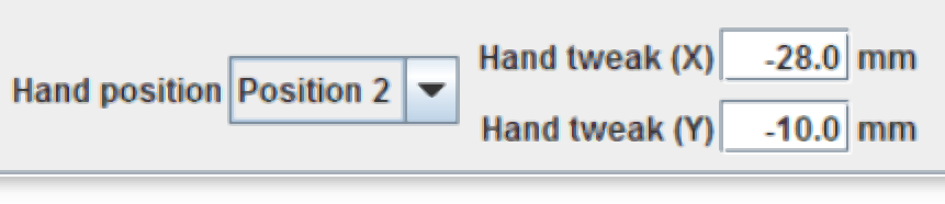
For drop bars, you may find that some nudging is required to the rider to get the dimensions correctly placed on the hood. I’m open to hear about using a better location but this is what I did to place on the SRAM type perches.
When working with any of these prints, it cannot be stressed enough that the designer needs to have a very clear and specific understanding of what the driving dimensions are and what the driven dimensions are. I see many people referencing poorly chosen dimensions without understanding what is being done.
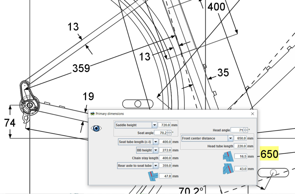
One very valuable driving dimension (in modern design) that can be used in BikeCAD is the ‘Rear Axle to Seat Tube’ input in the primary dimensions menu. Quickly summing the rim radius, max tire height, and flux gap will produce an important radius. In this case, 359mm. This is the distance that the seat tube, yokes, and bridges need to be from the rear axle. Using this as a driving parameter will keep the seat tube clear of the tire at any actual angle. That makes offset seat tubes much easer to produce as the effective seat tube angle can be targeted.
It is possible to take setup prints to a much higher level than I show here. I’m trying to focus on the very basic fundamentals in what I show. An elite racer may want to be very specific about brake rotor sizes and gearing as well as other choices in setup for a particular race. In this case it may be useful to develop a few different templates to show this without producing an insane mess. Please take my work as a starting rather than end point.
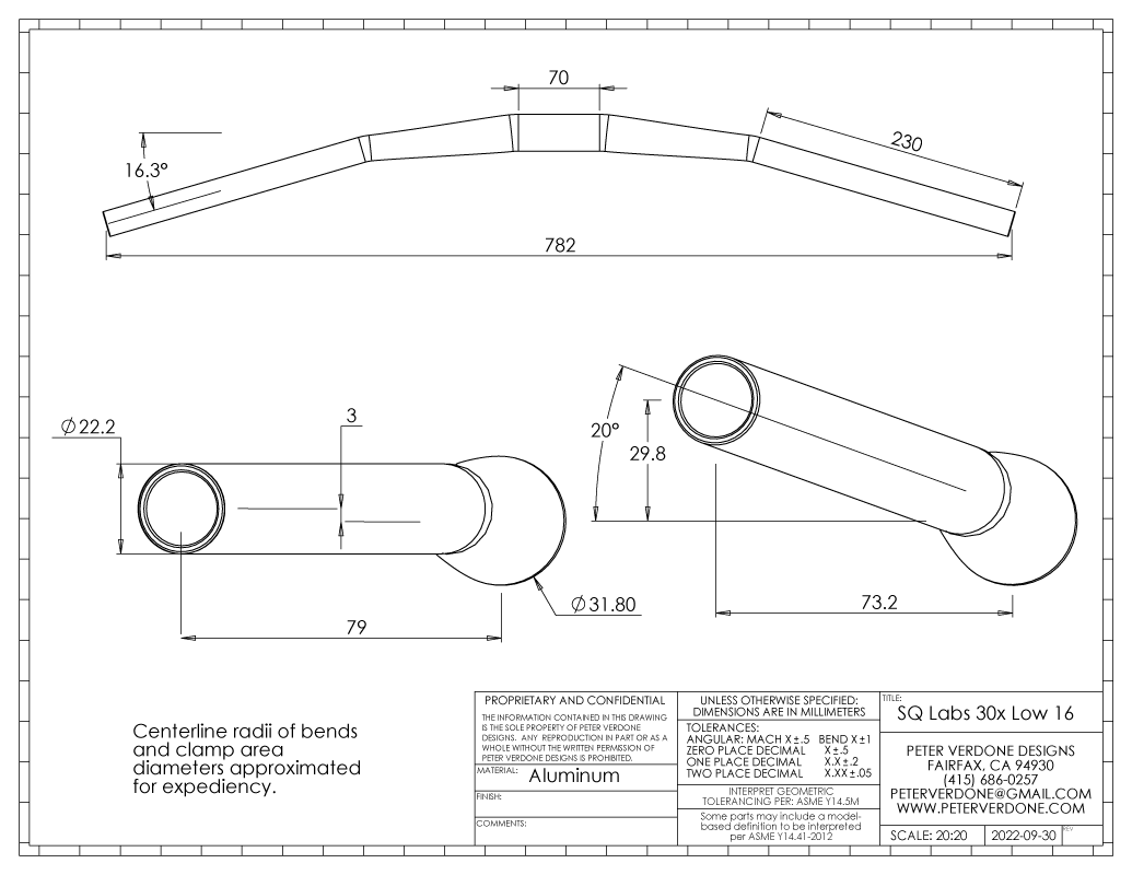
For folks working with flat bar designs, the first thing that they will struggle with is handlebar geometry. This as handlebar manufactures do not publish meaningful dimensions for their product. There will need to be some investment in learning to measure handlebars.
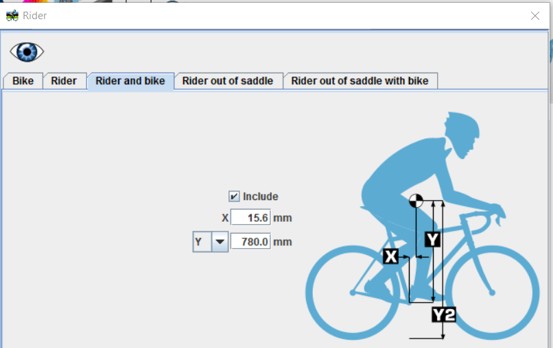
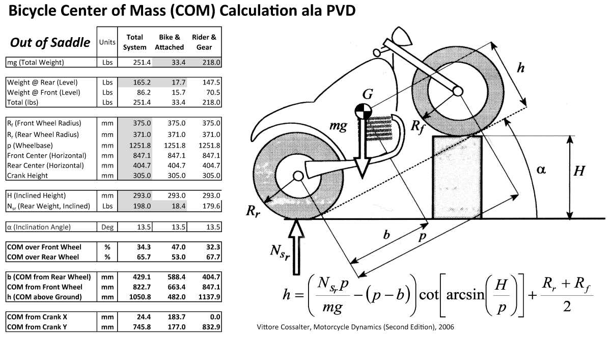
Center of Mass information is extremely valuable for understanding a bicycle design. Few perspectives carry more weight that this, although it is rarely used. There are several COM points that can be displayed in BikeCAD, although the most valuable will be rider in saddle and rider out of saddle. This can be hacked for another position that is important.
The problem is that we generally need information that we can only gather in a lab, after the frame is complete. So approximations must be used. These are still quite valuable and can tell the designer a lot about what will happen in use.
It’s also OK to have redundant dimensions in these prints as their goals are quick and easy communication, not inspection documentation. I don’t worry about this kind of thing in these prints as the goal is clarity.
So, here we go. A pair of BikeCAD dimensions templates that folks are free to use. I hope that these inspire a bunch of creative uses and learning.
http://www.peterverdone.com/wp-content/uploads/2026/03/2026-03-08PVDFlatBarDimensions.bcad
http://www.peterverdone.com/wp-content/uploads/2023/10/2023-10-28-Drop-Bar-Dimensions.bcad
Just drop these into the DIMS folder for your install of BikeCAD. Here is an approximate path:
C:\Users\CHANGE_NAME\AppData\Local\BikeCAD Pro 20.0\app\BikeCAD_20.0_configuration\DIMS
Maybe we can start seeing some other templates getting distributed from other folks. My 1:1 Title Block is very useful for sharing on social media such as Instagram. Capturing your design and communicating it well on this platform could help a lot of others get good ideas.
http://www.peterverdone.com/wp-content/uploads/2023/10/2023-10-27-PVD-Title-Block-INSTAGRAM.bcad
Approximate path:
C:\Users\CHANGE_NAME\AppData\Local\BikeCAD Pro 20.0\app\BikeCAD_20.0_configuration\TITLEBLOCK