Last March, early in the COVID-19 lockdown, I set out to design and build a new frame fixture for myself. This was need-based on many levels. I wanted something amazing. Something better than anything I could buy. A fixture for a new way of doing things. The result was the PVD Cyberdyne System. I still look at it in awe.
Nothing is ever perfect in the first draft and the custom CNC machined construction used was out of the reach of the average person. I found a few details that could be improved. I also started seeing new ways of solving the problems once I had the tool in front of me and in use. This often happens when you first make something. That all started last July just as the fixture was born. I kept having new ideas. Things were stewing in my mind. I started thinking that I could produce something for a lot less effort. I thought that I could do better.
I was discussing some of this with another bicycle tooling designer. He had a mature design for a tool and felt that there weren’t any real improvements that could be made. This happens to a lot of us as we build institutional ideas and architecture into something, we feel it’s ‘unchangeable’, that decisions made five or ten years ago were correct then and they are now. I lectured that with a fixed design in hand and in use, that to find real improvements it’s often helpful to start with a ‘clean sheet’ of paper and design a new version of the thing with fresh eyes but with the experience gained from the past. With modeling software, the investment is just time and effort. Little money needs to be invested. This helps to break us free from our investments and fixations and opens us up to different ways of solving the problem. While I was trying to get this guy to do this for his design, in my mind, I knew I needed to do the same. I knew that there were other paths.
Months went by after that. I got focused on other projects. I didn’t really need to do much for my tooling and the projects at hand were new and exciting. The ‘clean sheet’ rework of my design was falling by the wayside. It happens. So many ideas, only so much time and attention to spare.
Then, in late November 2020, an aspiring builder appeared on the scene. Benjamin Land had garnered my attention by posting some novel handlebars on a frame with geometry similar to my PVD Warbird design. It was nice to see someone, even a novice, understanding some of the modern design principles that only a few top builders are capable of discussing. In February 2021, Ben began sharing on YouTube as Shieldmaiden Bikes. The kid had brains and balls.
Ben wasn’t coming at all this like your average wannabe framebuilder. He was trying to actually understand what he was doing. This is extremely rare. Sharing his journey of discovery and teaching. He was trying to help others. He was doing good. He got plenty wrong but was earnestly interested in moving forward. I’d message him with some corrections and comments.
When Ben announced that he was going to build a klunker next, I knew I had to share with him as much as I could to help ensure he avoided rookie mistakes. Klunkers are not easy bikes to design if intended to be truly ridden. I’d email him with links and comments and reply to his. This was good for a while but he then took a left turn. He wanted to build a revised performance hardtail without all the early mistakes his current bike had in it. He really needed better tooling to move forward with anything he was going to do.
This is exactly the type of person I write for on my website. Someone looking to learn and grow. This is the person I’m trying to help. How do I move this guy, and others like him, forward on their journey without them having to waste all the time I had to because there wasn’t somebody like me (now) to help my younger self? People often want to know why I’m so angry. It’s because there wasn’t anyone around to teach me about bikes when I needed that myself. I had to do it on my own, surrounded by stupid tradition and false prophets. I want kids in high school and university to gain access to this method. So they can make things, properly, and bring new things into the world. I want them to dream bigger.
In discussions, I told Ben, “I know that there’s a way to make a bare bones version of the Cyberdyne System. Something very cheap but far better than you can otherwise have for the money.” I told him I’d take a look into it for him. I glanced at it. Then again a week later. I wasn’t seeing it right away so I let it stew. Two or three weeks later, I dove in full blast.
Robert Brewster : Skynet? The virus has infected Skynet?
John Connor : Skynet IS the virus. It’s the reason everything’s falling apart!
Terminator : Skynet has become self aware. In one hour it will initiate a massive nuclear attack on its enemy.
Robert Brewster : What enemy?
John Connor : Us! Humans!
As the Cyberdyne chip is the foundation for the SKYNET, so that original fixture is the foundation for the new version.
SKYNET is the virus.
At first it was a struggle figuring out cheaper and cheaper systems and methods, of course. Designing so that a simple manual mill and lathe could produce an exceptional fixture is not easy. Making good stuff cheap rarely is. As Blaise Pascal famously said, “I would have written your a short note but I didn’t have the time.”
Once I started making some progress, I could see more and it got a bit easier. There’s a few weeks of work here, on top of what had been done for the original fixture. I really busted my ass on this. My goal was to make something that could really democratize modern bicycle development. You may not have fancy machines or apprenticeships under your belt but you can now have the best of tools, for very little money and effort.
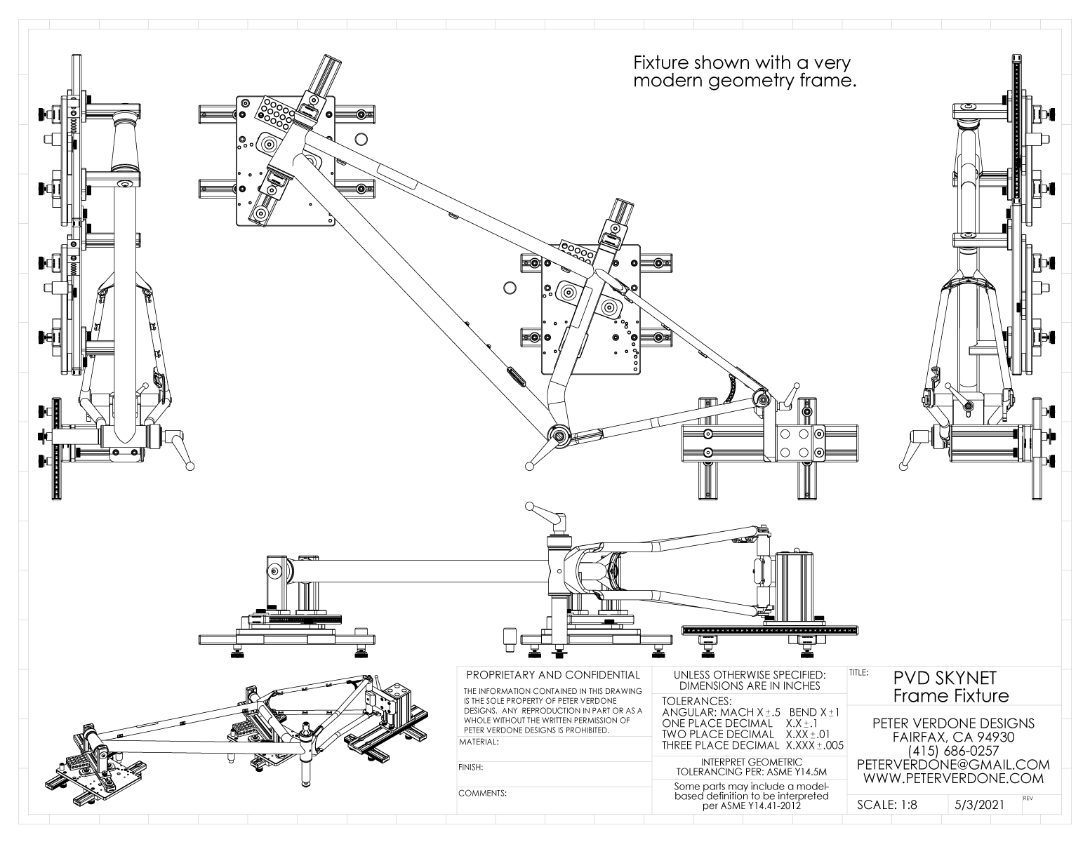
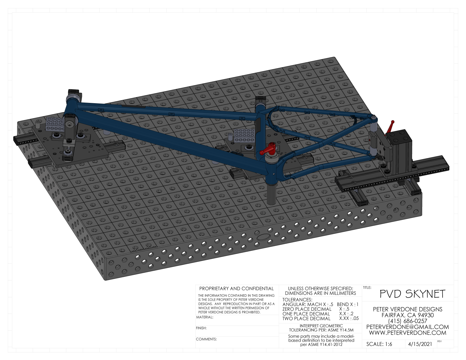
Why is this so important? Simply put, no other frame fixture offers as much flexibility for building. From fully modern hardtail and klunkers, to all-road frames, to full-suspension e-bikes, this fixture opens possibilities. Everything is based on an X/Y raster. Each part of the fixture is modular. Each can be modified, improved, removed, or used as they’ve been designed from the start. Suspension bikes are made as simple as possible since each pivot can be located accurately, as designed, using simply mounted tooling. Every point on the frame can be located in space as the print specifies.
Ranges:
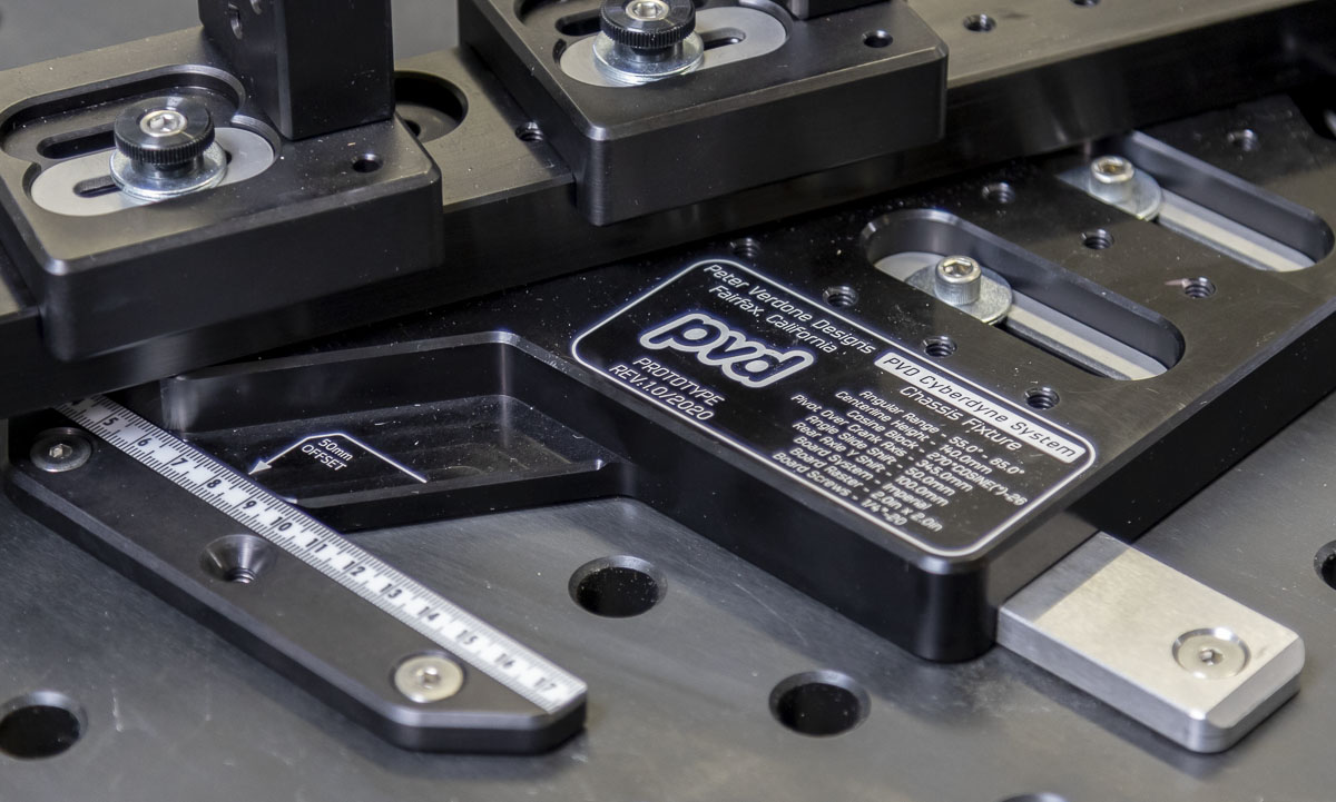
Head Tube Angle: 9 to 91 degrees (as shown, modified angle plates for additional range)
Seat Tube Angle: 9 to 91 degrees (as shown, modified angle plates for additional range)
Front Center: 0 to +∞ (Limited only by table or ganged table sizes)
Seat Tube Offset: -∞ to +∞ (Limited only by table or ganged table sizes)
Chainstay x: 0 to +∞ (Limited only by table or ganged table sizes)
Chainstay y: -∞ to +∞ (Limited only by table or ganged table sizes)
Crank Shell: 0 to 270mm Symmetric (as shown, modified centerline height for additional range)
Axle Spacing: 60mm to 197mm (as shown, modified centerline height for additional range)
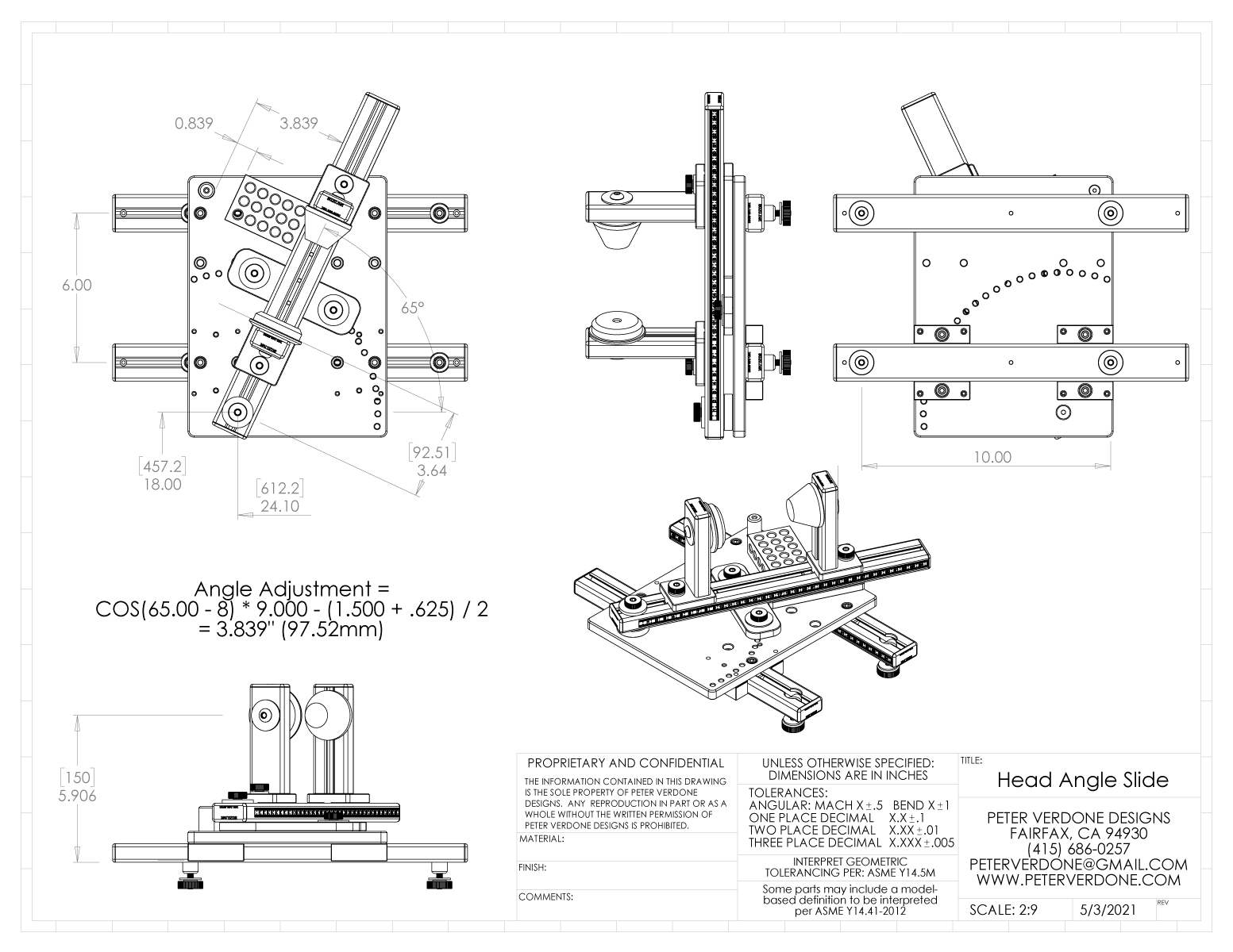
The head tube and seat tube adjustment modules are very similar, almost all of the parts but the pillars and connection points are the same. They work in the same method as the Cyberdyne fixture to adjust angles. If the fixture constructor has the ability to engrave a degree wheel on the plate, that’s fine. It’s not needed though as very precise angular settings are possible by using the 9.000″ cosine bar built into the plate. The formula for the bar offset here is COS( HA – 8 ) * 9.000 – ( 1.500+ 0.625 ) / 2. Here, a 65 degree head angle is set by setting a 3.839″ gap from the pin to the beam. This is made even easier by stacking in a 1-2-3 block and measuring 0.839″ of gap. Notice that a 0.05 degree change in head angle from 65 degrees changes the offset 0.007″. That’s an amazingly high degree of precision available with a simple measurement, or using a cheap gauge block set. Of course this changes sinusoidaly as the angle changes but in the working area this is what we are talking about.
No other fixture I know of can work to this level of precision and it is remarkably easy for anyone to adjust.
The dummy axles used by the fixture are the Anvil/PMW type. Anyone that has Anvil rear 2.5″ spaced axles of old will find that they interchange directly into this design. For current supply, Paragon Machine Works supplies them in most common dropout widths and axle diameters.
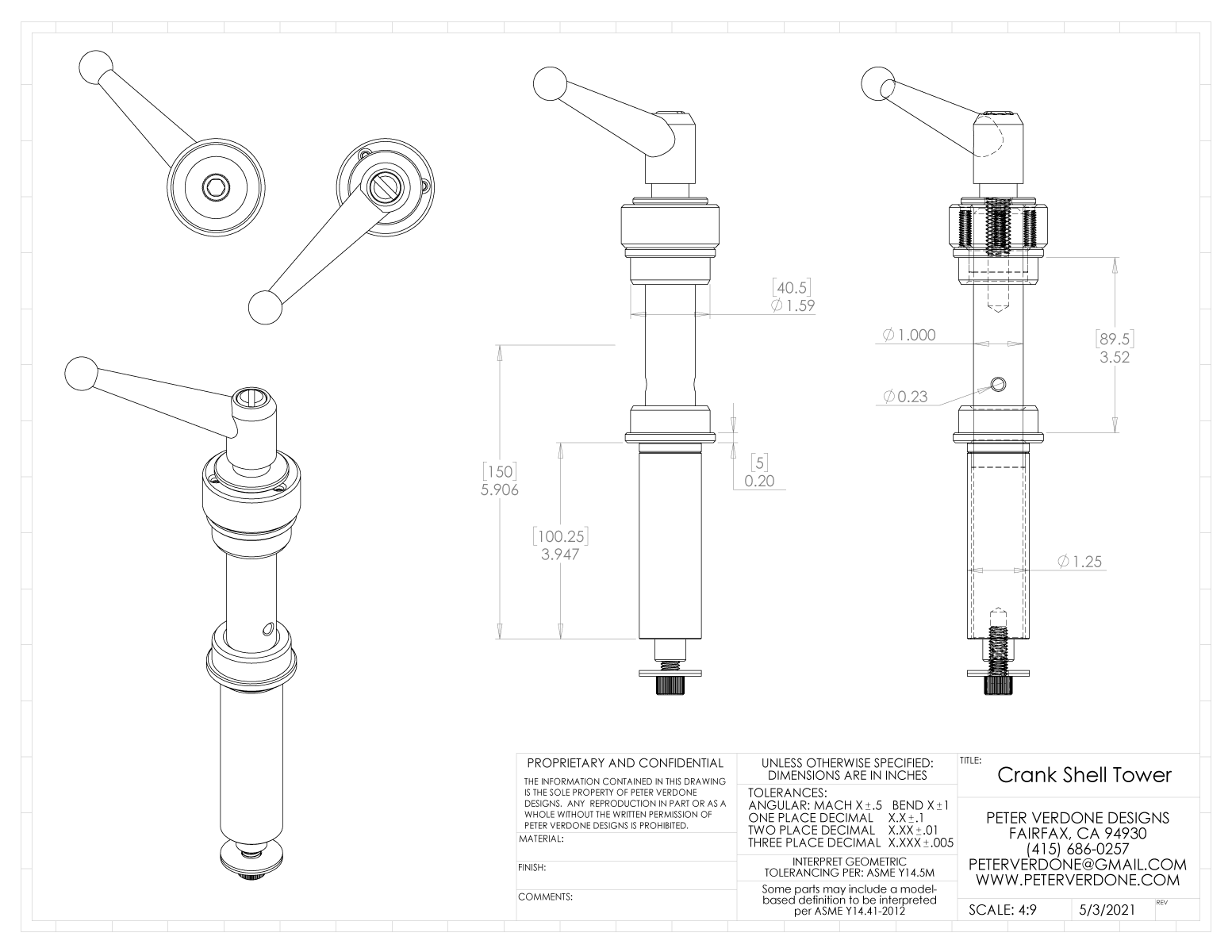
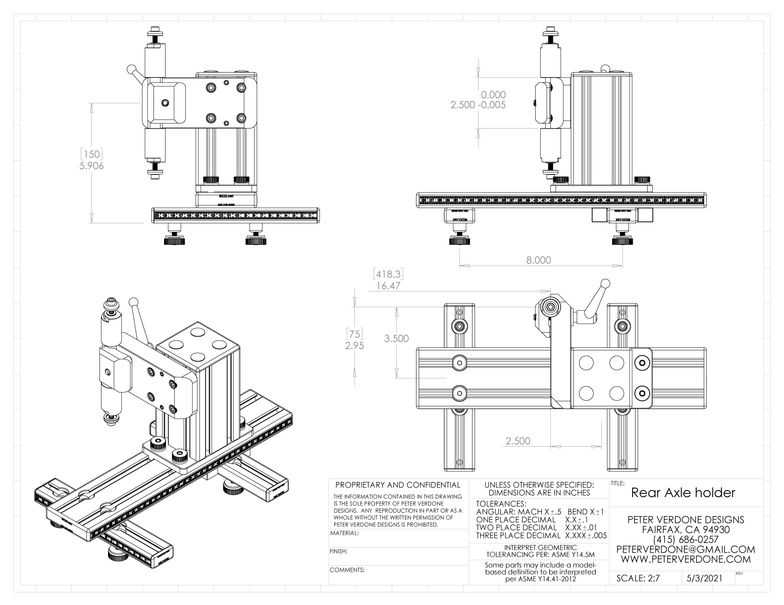 The crank shell is rigidly supported on both sides. The top clamp for the crank shell has a gear puller system (of sorts) to ensure that even with a tight fit for positioning the crank shell and an expected amount of welding distortion, the frame will still be easy enough to remove. If you are cutting corners or keep a looser fit here, this part can be the same as the bottom. I believe that both sides of the shell should be supported for best results so I’ve drawn that in place. This is an important way of designing the post that others leave out of their fixtures.
Changing the shell width or interface is done with simple reducers and either trimming a 1.25″ tube to length or adjusting a spacer.
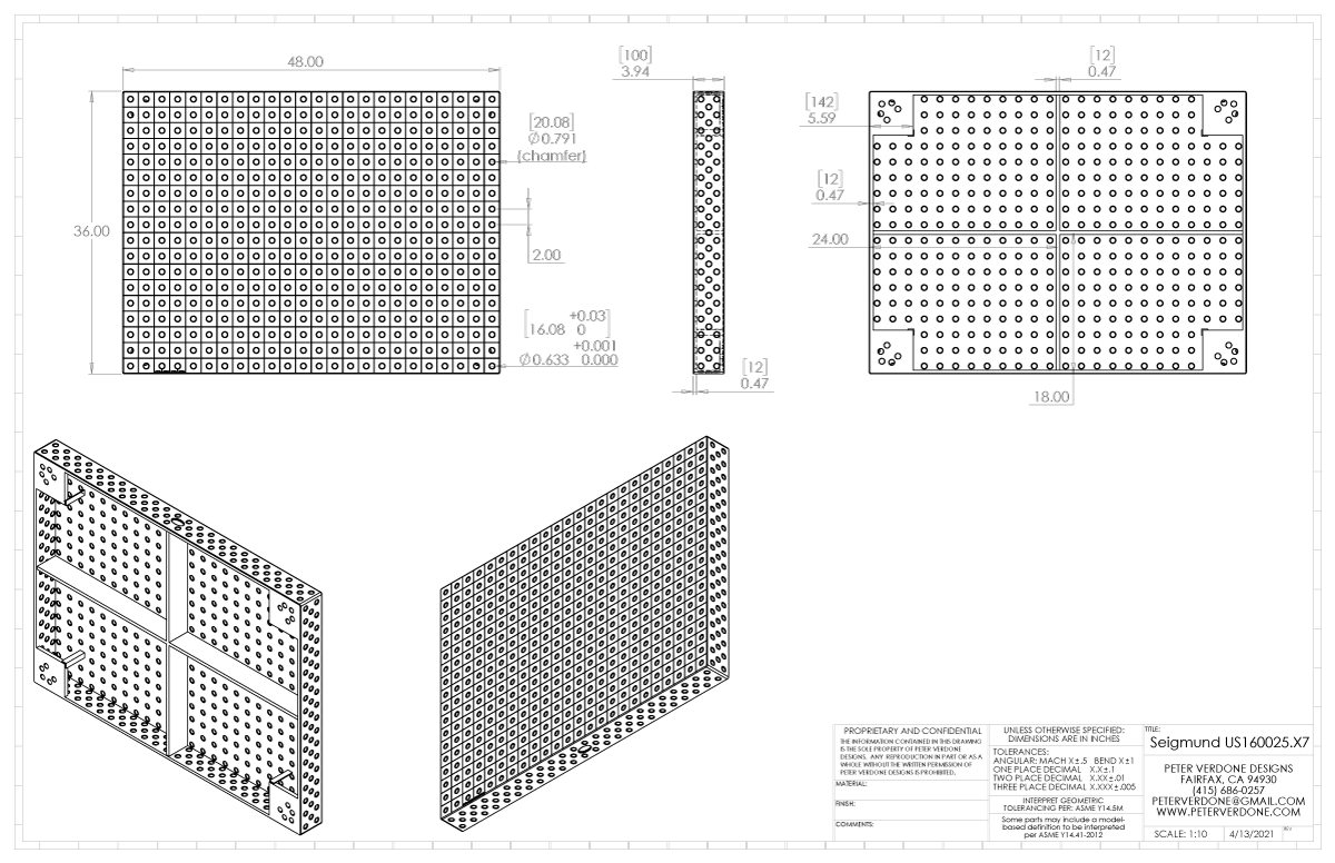
It should be made clear that this tool is based on the investment in an imperial welding table with a 2″ x 2″ x 5/8″ raster. That means Strong Hand Tools RhinoCart, Strong Hand Tools BuildPro, or Siegmund Imperial tables are perfect for this. Already have one of these in your fabrication shop? You’re 95% done. In fact, while I had initially built around the 48×30″ RhinoCart, Ben Land was able to save money by picking up locally a Seigmund 48″x36″ table…which is actually about the best small table to be using so I’m very jealous. It’s #US160025.x7 and currently cost about $2099+. A RhinoCart is $2,090+. Different situations will necessitate different choices but any of these are very good.
In a completely metric environment, with a 50mm x 50mm raster table, some simple changes to the design will produce a really wonderful system. Once this is all proven, I’d be happy to share a model to someone working in Europe or another metric land. The rationale of the system has been optimized for this version to easily happen. Were it to come up, I could prepare that design in a few hours.
The welding table is the real investment. You get a platform for any welding project, and killer bikes. That’s huge! It’s one thing to make an investment to be able to weld a bicycle together. It’s entirely another to invest less money, be able to weld bikes together, and also anything else you want to fabricate. Investing is important and you really can do that wrong. If you don’t see the value here, I don’t know what I can say that will convince you on this method.
 Let’s say you’re not able to buy a $2k+ welding table. I get that. Some kids are broke. The goal of this design isn’t just so that home gamers can have toolroom grade fixturing to develop bikes with, it’s so that young people and broke fuckers can play the game. I want high school and college kids to make bikes, well and correctly. If you can’t drop $2k, no problem.
There’s a cost saving workaround engineered into this design, using a $40 sheet of 3/4″ MDF , cut to 57″ x 34″. This material is available everywhere, fairly dimensionally stable, flat and easy to work with. Have your buddy cut a hole raster on their CNC router, extra points for fancy rounded corners and a beveled edge. Or very carefully, layout and cut a raster by hand in the locations needed. It’s a minimum of thirteen 5/8″ bored holes in the MDF to make a board useful for making bikes. A few more if you’re looking to make full suspension bikes. The MDF surface can also be improved by backing it with an 8020 frame to help keep in in plane and giving the user a way to mount to the wall or legs. This isn’t the most desired case but it will work fine if done accurately and then supported in a reasonable way.
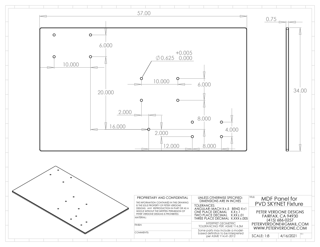
In discussions on the use of MDF by younger people building this fixturing system, lacking a CNC router and needing to do real accurate layout and boring of the 13 holes, doubt arose that this could be done perfectly on the first try. For that reason a bail has been built into the rails. Should accurate positioning become a real problem on the MDF board, bore the holes slightly oversized and position the rails with the pins clamping them in place but enough to nudge into position. Once the rails are aligned and all measures are confirmed, 1/16″ holes are predrilled and the rails are screwed into place using #6 x 3/4″ flat head screws for particleboard and fiberboard (McMaster #90252A104). A little wood glue in the hole before the screw goes in is a gangster move.
The thing about the Cyberdyne platform is that you can hack it as you please. You may not be able to do your best work now but you can get something going. Later you can improve parts of the fixture. You may not even be able to afford the welding table now, but you can get something going that can be translated to that when you can afford it. Have an idea or doing something strange, mock it up and bolt it down, you can do that with all the precision you can muster in a meaningful way. That’s one of the great things about the modular design. Get up and going and improve as time and money allows. Amazingly long chopper type bikes, fine. Goofy tall circus bikes, fine. World Cup DH bikes, fine. Triple tandems, fine. You can do anything you really want, just get a table that is scaled for what you want to do and bolt on whatever tooling you please. It’s all pretty low cost with a few sticks of 8020 and a few hours of CAD and milling.
Much of the actual fixture is constructed of 8020; 1575, 3075, and 3030-S extrusion. Each of these have a black anodized option that I highly recommend using if cost allows as it will be a bit more durable; 1575-Black-FB, 3075-Black-FB, and 3030-S-Black. Special t-nuts are made from 8020 8900-36 t-nut stock. Finish caps are also shown in the rendering. This does a lot of heavy lifting and minimizes the actual machined parts considerably. Want to be a baller? Have 8020 cut all of your material to length prior to anodizing!
The rest of the material is easily sourced from McMaster-Carr or your local industrial supplier. Ruled tape is from Oregon Rule or McMaster.
One special tool that is needed to produce the locating rails for the fixture is a Melin A-2424-DP Drill Mill, Hss, 90 deg., 3/4″ x 1-11/16. It’s available for $38.79 from Zoro, PN# G4991380. While being simple, the stepped bore with chamfer that is placed on the 8020 #1575 extrusion mates with the pin to center it and locate quite precisely on the table raster. This is really the heart of what makes the SKYNET work, beyond the Cyberdyne adjustment layout.
“Skynet begins to learn at a geometric rate” – T-800 Terminator
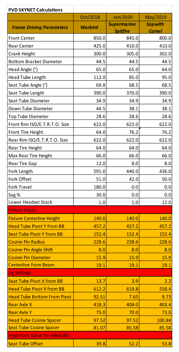
Lastly, I think that it’s important for folks that build bikes to learn about actual frame geometry and design if they are going to be making a bike. Not many do this and the results are punishing. For this reason, I’m leaving out the math that is required to set this fixture to the users. Below is an example of driving parameters, fixture inputs, and settings. This is a simple enough spreadsheet to compile and important for the novice to produce prior to building bicycle frames.
This is an important part of learning how to design and build bicycles. You need to learn what the numbers mean and what they go into. Do this.
Here is the sheet for the SKYNET fixture as shown above. Note that the plates can be mounted at any height and the math will correct for that and place the axii correctly. That’s the Cyberdyne System at work.
Ben Land is in the process of producing this fixture. He is producing detailed drawings for making the parts. He is going to tolerance them and test the process. I believe that he will be sharing his journey on his YouTube channel so subscribe there for his updates.
When he is done building his fixture, I’ll share that, discuss his actual costs and issues that he may have had during construction.
I’m going to speculate that a fixture (as shown), on a MDF board could be constructed for less than $750. Show me a frame fixture that works this well for this little!