I’ve been so busy over the past year and a half. I’ve done and incredible amount of work on my designs and tooling but still don’t have a finished bike to show for it. New fixtures, new designs, new everything. The new normal is ‘new’.
In the background recently are projects that are large in scale, and one is finally drawing near the end. The new All-Road platform. This bike was a clean sheet design that will hopefully, keep me six years ahead of everyone else. It’s a big project with new custom seat and chainstay yokes, custom dropouts, custom head tubes, evolved handlebar system, custom caliper mounting, custom caliper adapters, and a radical all-road geometry built on years of evolutionary experience with clearance for 622-53 tires. It’s going to be a sick replacement for the already incredible PVD T-47 Airspeeder.
As I had drawn to the end of the design phase of all these parts and was wrapping up prints and files for the machine shop, an opportunity arose. Metal printing parts. This isn’t a new thing. Many people are using 3D metal printed parts in bicycle production. I’m getting to it now since I’ve been so busy not just in the last year and a half but 3 years really, that being the Spitfire development. I just hadn’t had the bandwidth to deal with finding production and learning designing around AM. People that work around additive manufacturing will know that while there is a lot to learn and understand, it’s not rocket science. But when you are at your creative limit already, though, it’s hard to pile more on especially when it’s new and expensive.
It’s expensive.
Expensive.
If you are going to spend real money on parts, you need to be 100% right on your design and you get as much as you can for your money. This part is a very good example of doing that. As most know, I push my seat tubes pretty hard in my designs. Bends like the ones I use are expensive. A 30 degree bend about a 3.00 CLR for a 1.375″ x 0.035″ tube cost me about $30 each (not including material) in a batch a few years ago. Those tubes are running low and I needed to decide what to do for future bikes when I run out.
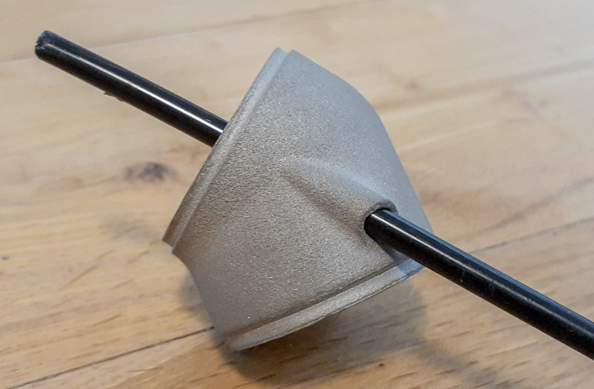
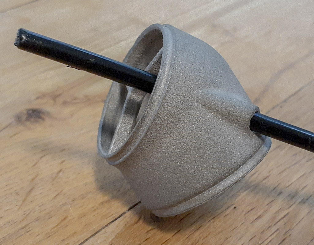
Another problem arose specifically with the All-Road platform. In recent years, manufactures of flat mount disc brake calipers have decided to forgo banjo bolts for hose routing into the calipers and dedicate the routing for along the mounted stay. This created a problem as my method had routed hose and housing down the seatstay regardless of caliper mounting location. On the new bikes, using a chainstay caliper mount meant routing the hose and housing had to be routed under the bike. This isn’t as simple as it sounds. It can be done easily, but is very difficult to do well and good looking. Downstream changes from this meant that the dropper housing would have to enter in the bottom of the seat tube instead of the top of the down tube.
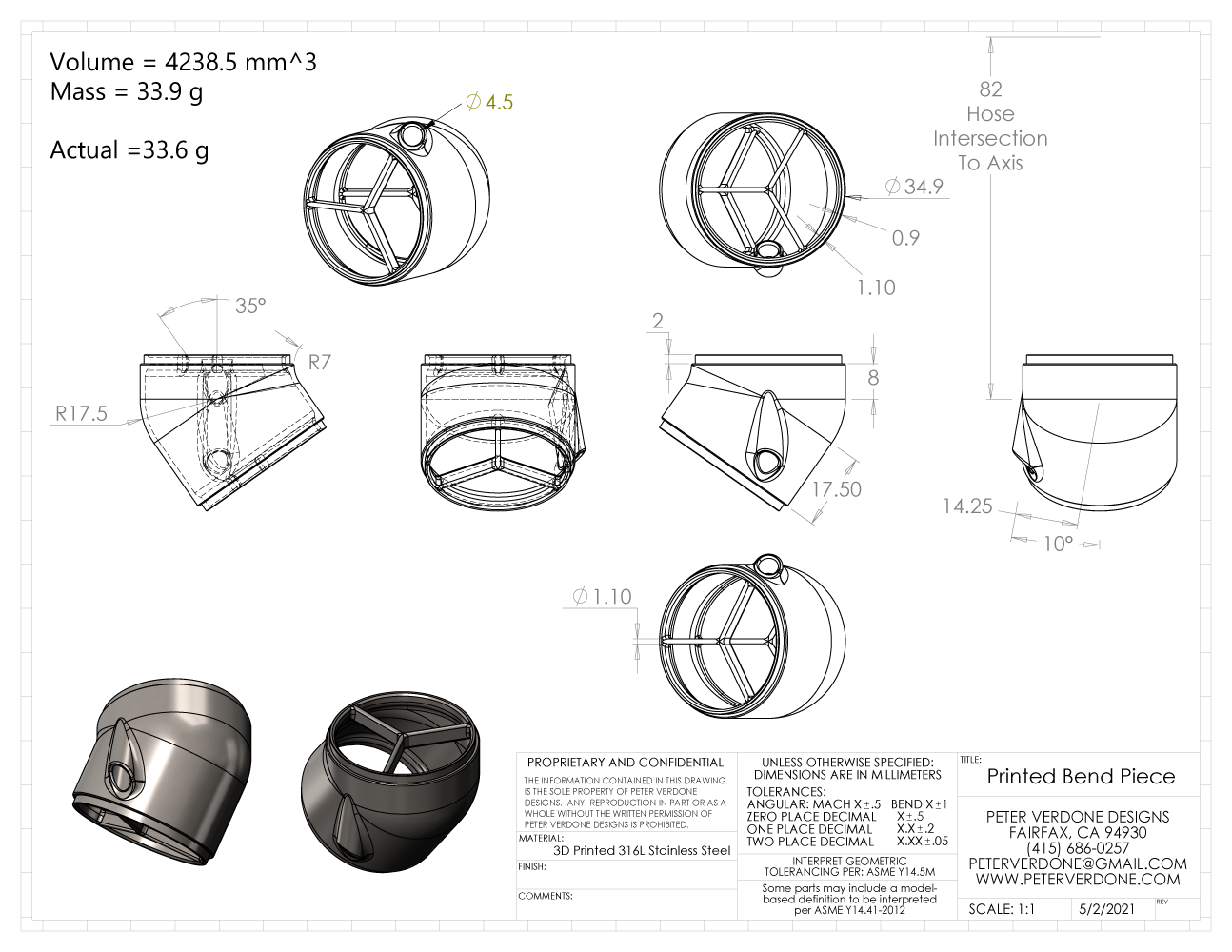
The combination of these issues had me thinking. Could I solve both these problems with one solution, 3D printing a bend lug and the routing? I drew up a few revisions. It was looking quite nice and could be a better solution than many of my options. Additionally, this part of the seat tube isn’t very highly stressed. If I screwed up, the down side isn’t as great as other mistakes can be.
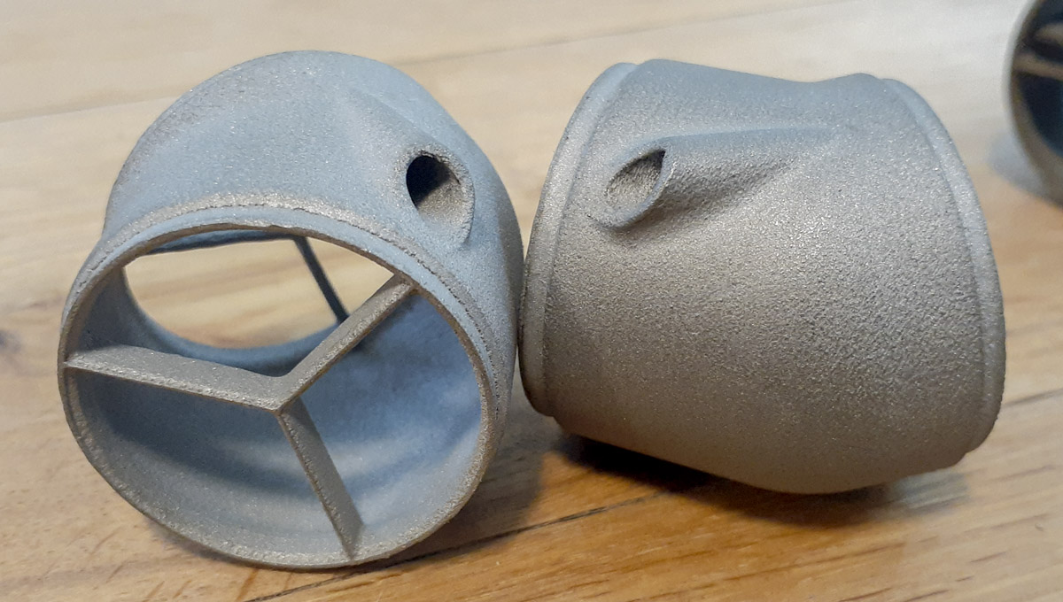
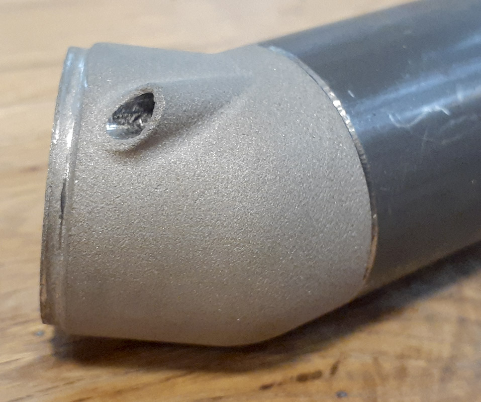
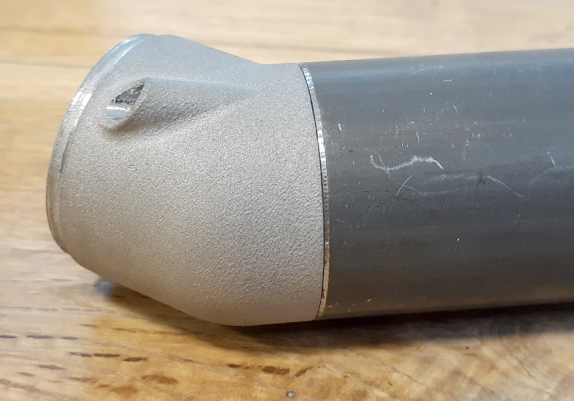
More, what if I made parts that I couldn’t otherwise produce traditionally. A 3.0″ CLR bend on a 1.375″x0.035″ tube is pretty nuts. That’s a mandrel bend and it’s really pushing the limits of what can be done with 4130, especially if you want it to look good. Since I’d be printing, that limitation didn’t apply. The shape could be anything as long as it worked well structurally and looked good. How about a 0.0″ CLR?! I went with that and it looked so cool in the bike. A drastic, chiseled look. If I’m going to pay, I want drama!
I had been asking around for a while about who folks were using to get AM work done. The list had grown. Most folks are printing to titanium. I needed steel. I also needed it cheap, cheaper than dirt. The part you see here today was quoted by one domestic printer at about $220 each plus shipping. That wasn’t going to happen.
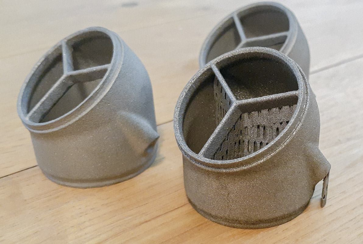
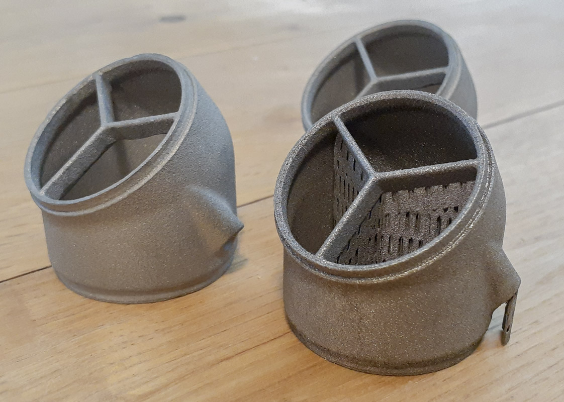
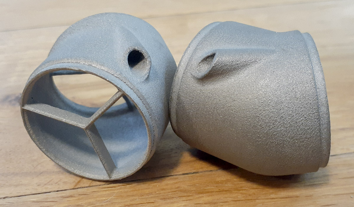
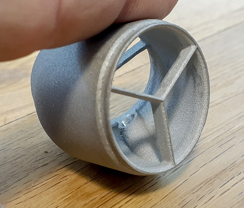
Eventually, I found a source. Considerably cheaper than the earlier quote but still on the pricy side. It was a bit of a shot in the dark but I went for it. The turn around time meant that these could be used in the new bikes if they looked good. I made the order and I waited. They showed up today. Three parts; two cleaned up and blasted, one as it came out of the printer with supports intact for my learning.
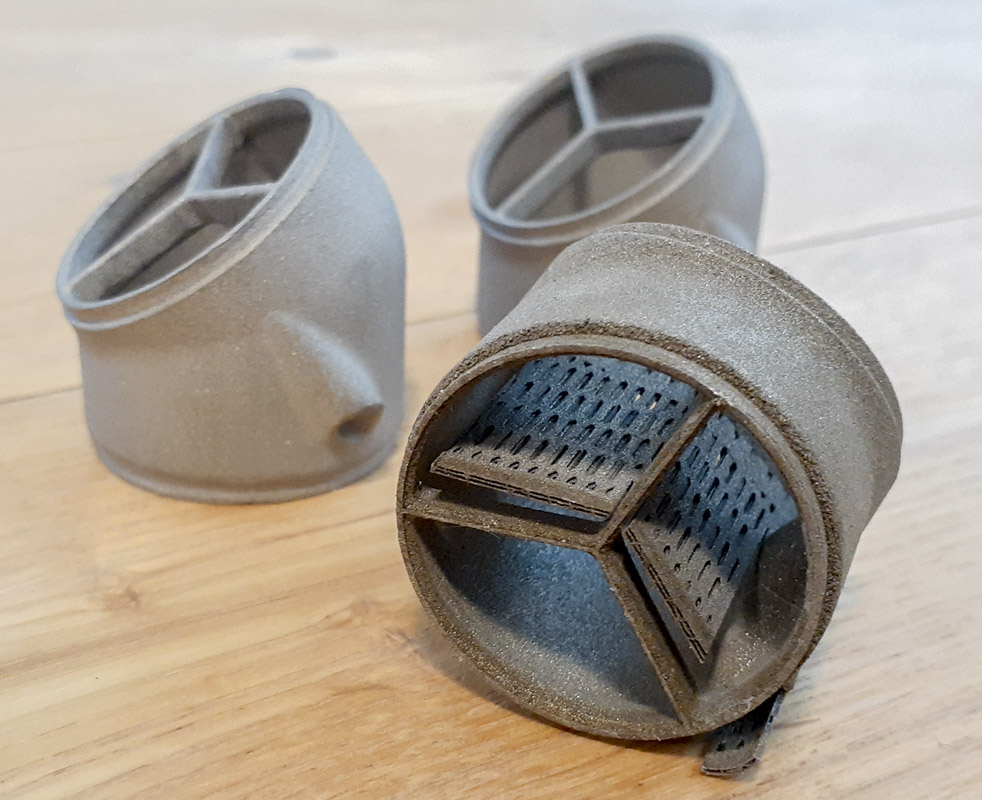
If you’re paying attention, you’ll notice that these were printed in SLM 316L Stainless Steel on a ZRapid SLM 3D Printer. While there are hundreds of powdered materials that can be used when printing metal, there are crowd favorites that tend to be loaded in machines and carbon steel is certainly not one of them. If you want exactly what you want, you’re probably going to have to pay to have the machined cleaned on both ends of production to get that. That adds a ton of cost to what is already expensive. 316SS is a common material that I can still weld into my frames so that really drove this decision. Weld-Mold 880 will fill the gaps.
It’s funny to think that the fiber laser engraver that I purchased last year is a similar type as used to make these parts, a 1064nm laser bouncing off a galvanometer. The difference here is that the printer uses a 500W laser instead of a 20W laser.
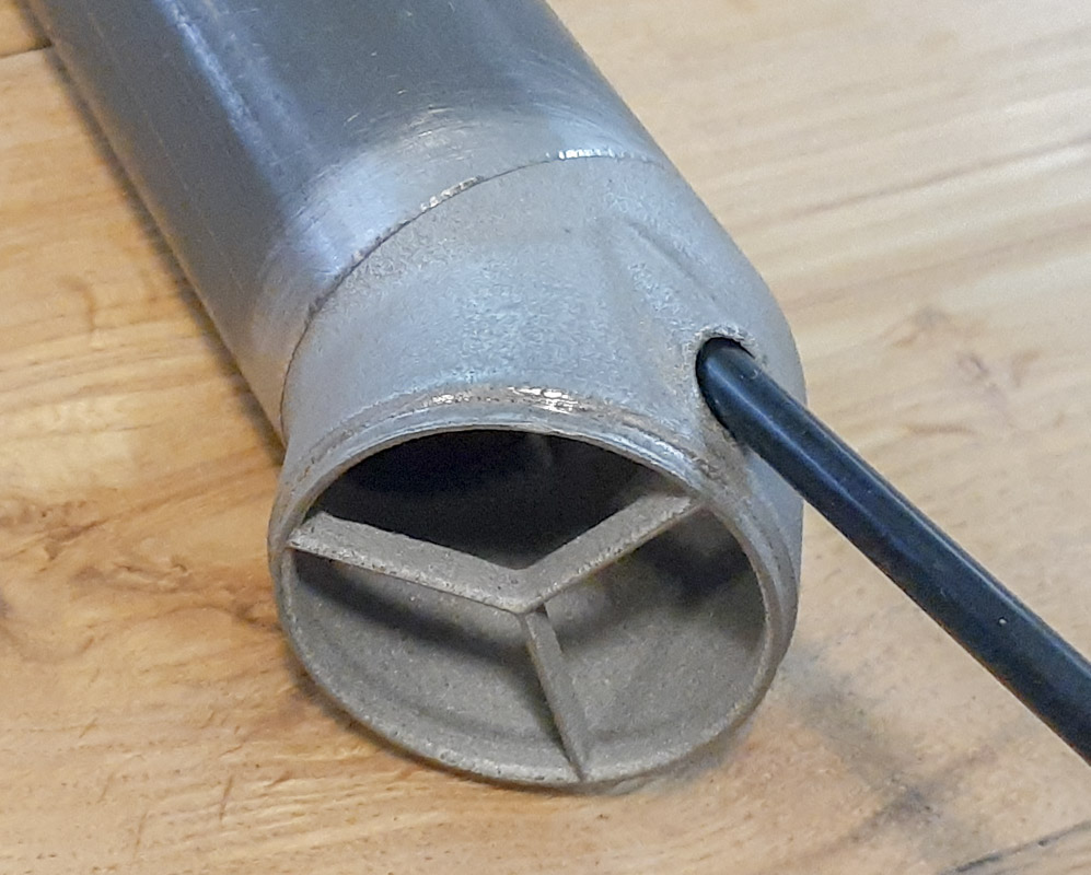
It’s known that there can be some shrinkage of a part during the sintering stage in the heat treat oven after the part is printed. The OD of this part theoretically should have been 1.375″. After some light cleanup, I measured the parts to be from 1.370″ to 1.373″ depending on where I measured. That’s about 0.4% to 0.2% shrinkage. This is something I knew about but decided to see what happened if I went with a theoretical model file since this isn’t a very precision dependent part. I did add supports to each end to prevent distortion and it looks like that was some help. I may leave those in place to give the part some additional strength in the bike as they add almost no weight.
While the finish in my photos doesn’t look outstanding, I believe that it’s going to be fine given that I’ll be powdercoating the finished product. With just a little working with emery, the finish feels smooth to the touch and will be excellent under powdercoating. I’ll give it a wire wheeling when I get to the shop and expect it to improve even more.
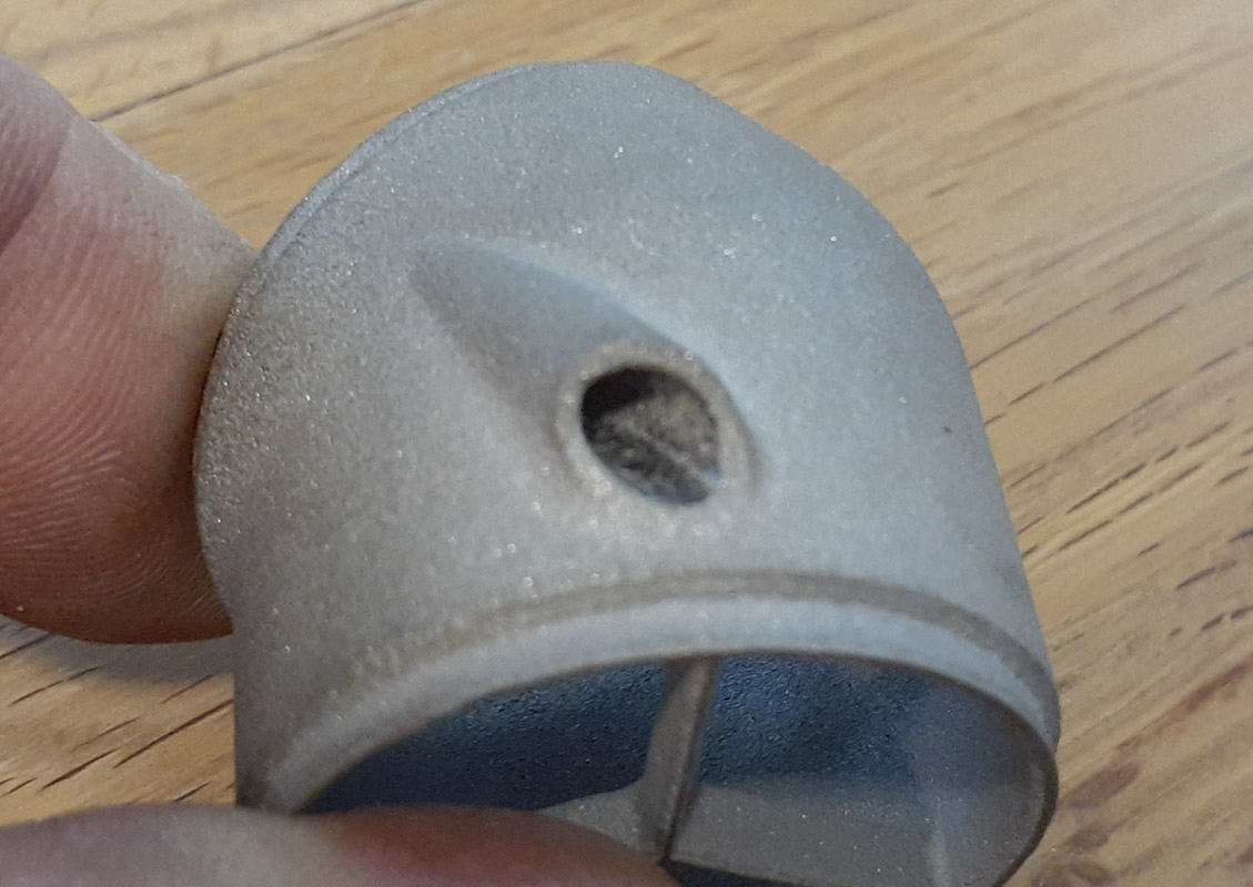
One design issue that I had was my specification of 4.5mm bore for the 4.2mm dropper cable housing. That was a bit tight in retrospect. I will move that up some, maybe 0.25mm more at 4.75mm. I cleaned it up some with a drill but these small IDs would be worth paying attention to. Paint and clearcoat take up room, especially at the start of this bore, so I may taper it some.
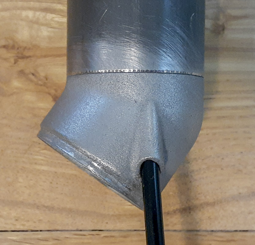
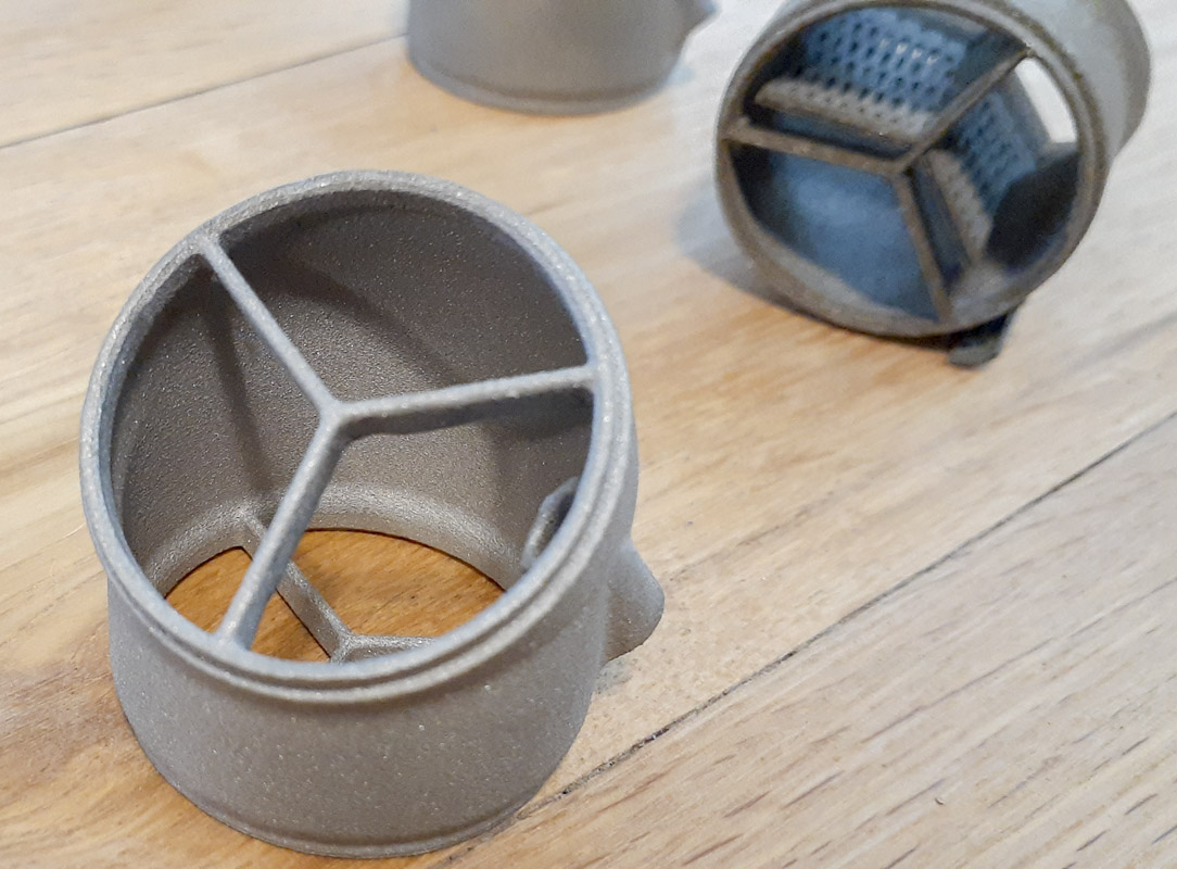
It can be seen in the images that, as we know, the bottom facing steps in the part are where the degradation in the printer takes place, maybe this is an issue in the housing bore also. I’m going to have to make some accommodations in my modeling for future prints.
Also, for welded parts, while I did add material on the inside of the part for welding. Looking at the parts now, I should have also given a little material to be absorbed into the bead for smoother welding. I need to play with this over time. A little more insertion into the tubes would have made some sense also.
Now the question; where do we go from here? Certainly, I’ll be doing more parts with additive manufacturing and learning the nuance of modeling for this type of production. Can I print MTB/AR fork crowns? Is 316L strong enough for that? Should I just move to titanium or aluminum printing and glue in carbon tubes? Suspension parts? All of this can be done as we see elsewhere. The problem now is experience, testing, and bank accounts.