This is a another diversion within the CNC controller box project. Another opportunity to learn things that I’ve never bothered to in the past. The more time I spend solving these practical issues the more it makes sense and the pieces start fitting together. Electricity is hard.
For my CNC controller project, I have to provide a way of cooling inside the enclosure. There is significant heat that the the power supplies and motor drivers produce when the system is working and the temperature inside the box will climb as it is used. This is not a good thing as excessively high temperatures will make the system struggle and even fail. Electronics like to be kept nice and cool.
A flow of fresh ambient air from the work room outside the box should be suitable to cool the inside of the box as that is typically used in most serious hardware.
This is a topic worth thinking about ahead of cutting holes in the steel enclosure. A good plan should be in place. I’m going to place a fan in the top of the enclosure, pushing rising hot air out. Fresh air will be drawn in from the bottom of the box, immediately past the drivers and larger power supplies that will be close to the opening.
I’ll have the motor drivers and large power supplied on the bottom for a few reasons:
- They are heavy and dense components, locating them low will help with the stability of the box when standing on it’s end or carrying.
- Significant electrical current is supplied to these components and is moving between them and in and out of the enclosure. Keeping that current as far as reasonable from where the sensitive controls and signal wires above are being routed makes sense. This is a simple and practical way of reducing electronic noise problems and other signal issues.
- They all create heat when working hard and keeping them together gives me a focused target.
- The enclosure has an existing opening that is suitable for air intake at the bottom. Having the heat sources close to that will help them cool.
Personally, I have a problem with mechanical fan noise. It drives me insane. There are others like me that will get up from a comfortable couch anytime someone leaves a bathroom fan on. Our oven fan is never used. I’ll even do this at a party. It makes me want to kill.
I want control of the fan that will keep the audible noise down to a minimum while still providing the cooling needs of the system. If I have one or several small fans, they will need to run at top speed with a large duty cycle to cool the box. If I use a large fan, it could run at lower speeds with small duty cycles to move the same amount of air. I have the room to fit a 140mm chassis fan in the top panel of the enclosure so it makes sense to go that route. A 140mm fan is huge, remember that the area of the fan blade sweep goes up with the square of the radius, also the velocity at the tip is higher for a given rpm. With a high quality 24v and 3000rpm fan, I should be doing well.
Control of the fan’s duty cycle and speed is a more complex issue than one would think. Strategy will help. How do I control the duty cycle and speed of the fan?
There are lots of ways to do this. I could:
- just connect a fan to the system so that it’s running while power is running through the enclosure. This is cheap and easy but loud and clumsy. 100% duty cycle, 100% speed.
- connect the fan similarly but to a switch that the operator controls. This reduces the duty cycle while the fan will be running and 100% speed when it is on. This creates opportunities for human error and over heating and adds a distracting control to the user.
- connect the fan with a switch that is thermally controlled so that the fan goes on when the temperature gets too warm. This is honestly the simplest and cheapest real solution. It would do the job just fine. Proportional duty cycle, 100% fan speed.
- connect a 2 or 3 wire fan to a 24v PWM output with a speed control knob. Reduced duty cycle and fan speed. Again, user error and attention can play a roll here.
- connect a 2 or 3 wire fan to a temperature controlled 24v PWM output. This is a very attractive option but there is limited controller support for this. This reduces duty cycle and fan speed without the operator being distracted.
- connect a 4-wire fan to a PID (proportional–integral–derivative controller) with 5v PWM output that would adjust the fan engagement and speed with regard to the needs of the system. This is more costly and complex but the quietest and most effective fan cooling system. The benefit here is that control is anticipatory and tunable. (this proves to be challenging to actualize and just results in reduced duty cycle.)
- An actual PLC (Programable Logic Controller) that will allow for any situation that could be programmed. This is the most expensive and complex solution. In such a simple system, it doesn’t merit. Total control of duty cycle, speed, and any other imaginable parameter.
- Something else.
Obviously, I first choose the PID.
More than many other reason for this choice is that it will give me some more experience working with another common and more complex control circuit. PIDs are very common in industry and can be found everywhere that heating, cooling, and time mix together.

For this project, I obtained:
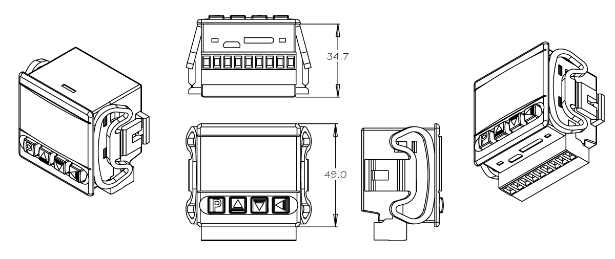
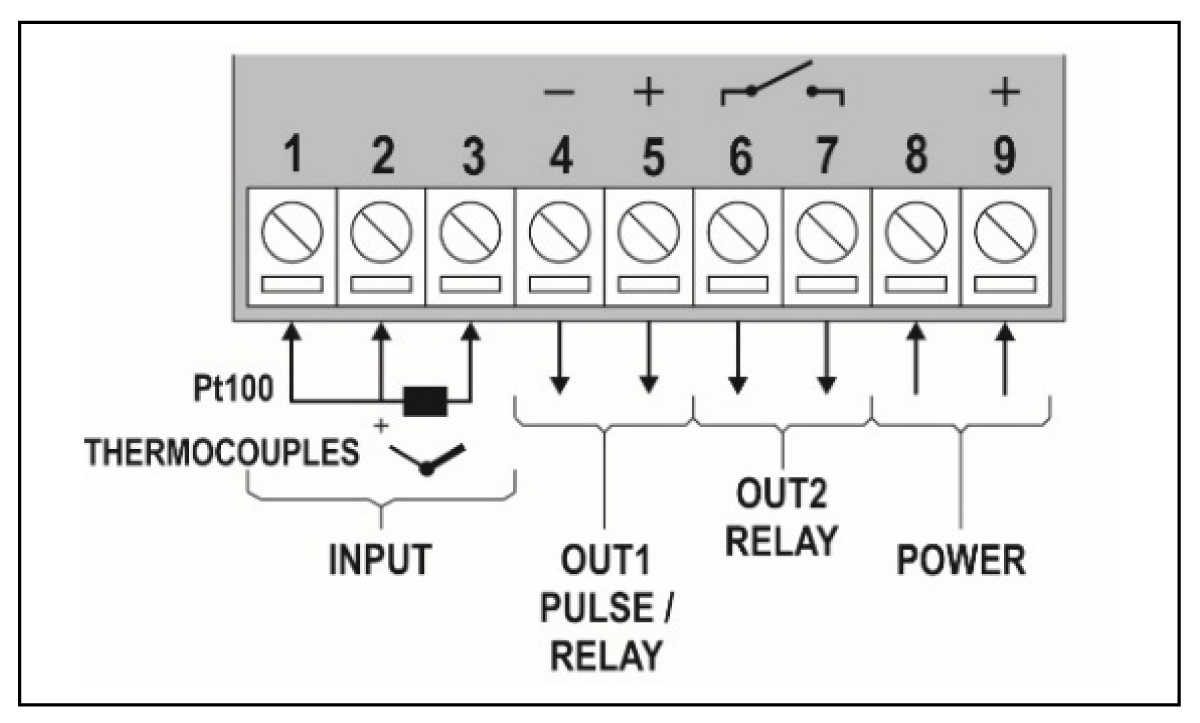
Novus Temperature Controller N1030
While this PID is a bit more expensive than I had wished to spend for this project, it had one huge advantage over many others, it’s depth. Most PID units are quite long. This is 35mm. Tiny by comparison with most of the important functions retained. This is important as there really isn’t a lot of room in the enclosure connecting to the front panel for a full length unit. This one is small enough to keep out of the way of most of the inside components.
On the N1030, the OUT1 PULSE / RELAY is a 5vdc PWM output (terminal #5 and #6). I was under the understanding that I could use this to control the fan speed.
I had a temperature probe on hand, left over from another device. I was planning to use it with this PID but there was an issue. It wasn’t correct. Here are the specs on that probe:
NTC (Negative Temperature Coefficient) Thermistor Probe ($2.89)
Stainless steel sheath and waterproof
Measurement range: -4°F to +200°F (-20°C to 105°C)
Length of wire: 1 meter
Size of probe: 5 x 25 mm
Output: 2 wires with 2-socket connector
Type: NTC 10k ±1% 3950
B-constant : 3380K +/- 1%
Typical Dissipation Constant: 5mW / °C
Probe insulation: >100 MOhm
Stress sustain: 9.8N (1kgF) for 1 minute no deformation
The problem here is that this is a thermistor and not a thermocouple. Thermistors are cheaper, less accurate, and work in a much narrower band of temperatures. Thermocouples are used in higher grade devices in more critical applications. The type ‘K’ variety seem to be the cheaper and most common variety.
Type K Thermocouples (Chromel+ / Alumel –) have a general temperature range of -200 to 1260°C (-326 to 2300°F). The wiring is Yellow (positive) and Red (negative). Be warned! The wire can be cut down or extended to any reasonable length. In fact, the wire itself can be a thermocouple when connected to itself.

So I order a thermocouple. It is a ‘fancy’ stainless steel sheathed tip and the wire is protected by braided metal:
Thermistor K-Type Sensor Probes Metal Head Probe for K-Type Probe Thermocouple Sensor & Meter Temperature Controller With plug, Long Probe (4×30MM) Temperature Range from 0 to 600 °CMT-6340-C (4X30X2) ($10.99)
Product Name : Thermocouple
Type : K Type
Temperature Range : 0-600C(32-752F)
Probe Diameter : 4mm / 0.16″
Probe Length : 30mm / 1.19″ (Not Included Flexible Section)
Internal Insulation : Fiberglass
External Shielding : Metal Shield
Total Length : 2M / 39″
Fork Terminal Spacing : 4.1mm / 0.16″
Color : Silver Tone
Weight : 61g
Playing with that thermocouple, I found a possible issue. The 4×30 metal head is thermally massive and it slows the signal reaction time significantly. In a liquid it would be perfectly fine but in air, it’s messy. I tested some twisted end thermocouple wire for it’s reaction speed and it was much much faster. I decided that I’d order a beaded end thermocouple to have a fast and slow choice. Testing on the bench is different than in the box. I’m not just trying to cool the air in the box (like an oven or freezer) but the hardware (drivers and power supplies). It could be that the slower thermocouple is a better choice IRL.
Product Name : Thermocouple TP-01
Type : K Type
Temperature Range : -40 to 482°F (-40 to 250°C)
Probe Type : Exposed Contact Bead
Probe Length : 30mm / 1.19″ (Not Included Flexible Section)
Insulation : Teflon
Total Length : 1M
Color : Blue
Cost: $7.99
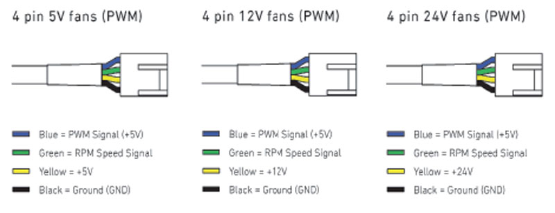
The fan is a Noctua NF-A14 iPPC-24V-3000.($32.95) At 140mm and a top speed of 3000 rpm, it can move a ton of air. Still as I’ve mentioned, I don’t want it to spin up to full blast every time a little cooling is needed. I want proportionality and keep things as quiet as possible. The power is 24vdc with 5vdc PWM speed control built in. The connection is 4-wire, two for the power and one for speed and one for tach feedback. These 4-wire fans are pretty amazing and worth consideration for any enclosure.
Typically, the PWM fan will have a Molex 47054-1000, KK 254 Housing with Polarization Rib, 4 Pin connector (2510 female). The male receptacle that I’m using in this wire-to-wire connection is off brand (2540 male, Everconn CH2510CH-04-03 ??). I made some cables with this connection for jumping to other controls without cutting the OEM plug.
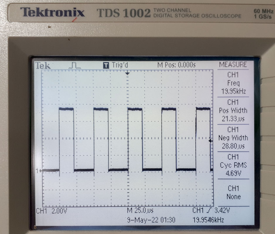
The PWM signal to drive a chassis fan is defined by Intel, “4-Wire Pulse Width Modulation (PWM) Controlled Fans”, September 2005, Revision 1.3“.
- Frequency: 25kHz nominal, 21-28kHz is acceptable
- Current sink capability: 5mA required, 8mA recommended
- Maximum voltage capability: 5.25V
- Maximum low-level output voltage (VOL): 0.8V
- Signal is not inverted, 100% PWM results in Max fan speed
The question, does the N1030 PID output a high or low PWM frequency? There is information to suggest that some fans will work with either. I may have that. Finding information on the PWM frequency has been difficult.
The problem that I was having was my error in reading the Novus PID manual, “PWM PROGRAMABLE LEVEL: From 0.5 up 100 seconds.” You would think that this unit sent out a 5v PWM signal that might be conventional as a real control signal. I did. It does not. What they mean is, 5V– on or off. The CPU fan has a target control signal frequency 25 kHz ( 21 kHz to 28 kHz). These are very different things.
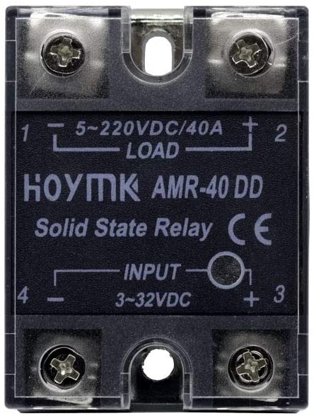
It was my inexperience that caused misunderstanding and I’m going to claim all of the real responsibility for the problem. Most other PIDs mark those pulsed outputs as ‘SSR’ as this is what folks will be connecting to. Now I understand, most people connecting a PID are going to use the pulse output to control a solid state relay. It’s obvious now. Once I connected a SSR that I had laying around, Hoymk DC-DC AMR-40 DD SSR ($18.88), it worked. Connecting the 5v line to that with 24v on the other side had the PID working perfectly.
The PID was controlling only the duty cycle of the fan! ….but this wasn’t going to control the speed of the fan.
It was time to change the course. I could have made ATmega328 IC circuit to produce my own PID that sampled the temperature and output a 5V 25kHz PWM signal for the 4-wire fan to reference. I may still do that but my initial reservation was not introducing another power supply voltage to the system. I’m really trying to limit my power architecture to 24v (control) and 48v (work). If I find a lul in my work, I’ll try to look into this further.
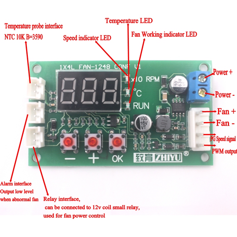
There are one or two small PWM fan temperature control boards on the market. Supposedly they will do what I want even as their control is fairly crude. I chose the Zhiyu FAN-1248 (1x4L) ($17.99) as I could use either 24v or 48v to run it. Documentation and support for these types of parts is slim.
- Temperature Measurement: -9.9℃ to 99.9 ℃, error <2℃ (1% probe with 70℃) 3℃(>70℃)
- Control Output Range: 10% —l00%(this is the signal output range; the actual situation depends on fan performance)
- Temperature Control Zone Range: accelerating speed temperature 5-94℃, full speed temperature 10-99℃
- Temperature Probe Specifications: NTC 10K B =3950K
- Speed Measurement: 10-9990 rpm, exceeding the speed displaying 999; resolution 10 rpm, display unit *10 rpm (speed measurement is based on common 2-pole signal fan design; most of the fans are 2-pole signal)
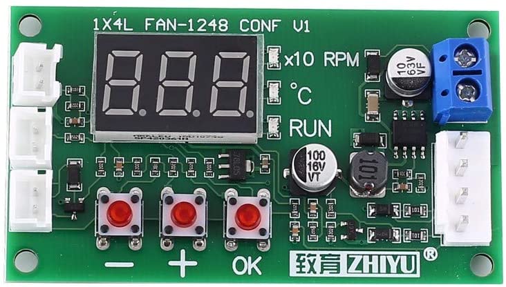
The frequency of the PWM signal was measured to be 20kHz. Just below the correct range but the fan seems to work fine.
24V power to this board is connected with the screw terminals. The thermistor, alarm, and relay plugs on the board are JST-XH-2P. This is fairly common in the lower tier import electronics that we find on Amazon or Ebay. Every hobbyist should have these on hand. It’s a connection only rated for 3 amps which is limiting for what can be controlled.
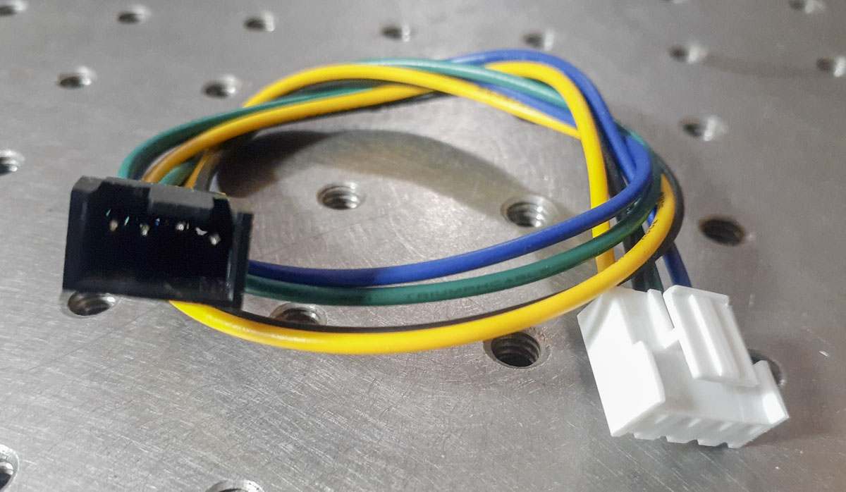
The fan connection is JST-VH-4P. This because of the power that may be going through it. It’s rated for 10 amps. That is a bit of a pain in the ass as it’s not that common on this level of component. Still, it gives a lot of elbow room for what we can do. I made an adapter to allow for easy fan swaps in the future. In this case, the wire pattern happens to be different than the specified 4-pin fan pattern. Be sure to account for this to avoid magic black smoke.
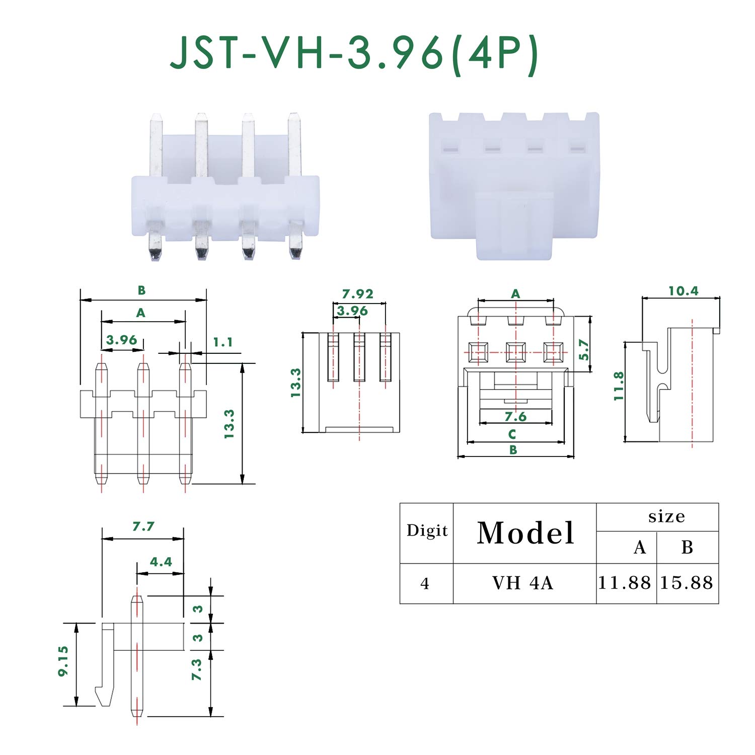
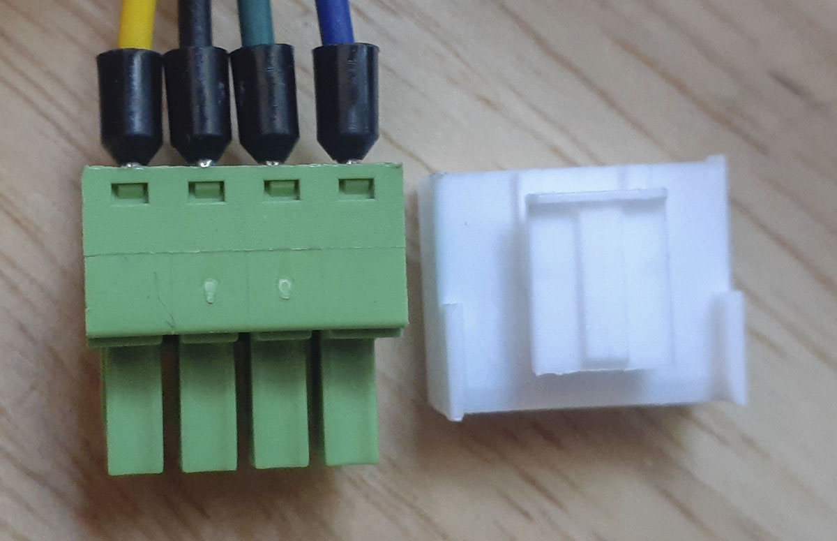
In a jam and without a JST-VH-4P plug for a day, I found that a Phoenix Contact COMBICON MC 3.81mm Printed-circuit board connector (MC 1,5/ 4-ST-3,81 – 1803594) worked. The pitch is just slightly off (0.15mm/0.006″) but nothing harmful seemed to happened. This gave the ability to use screw terminals when testing. This was a cool hack.
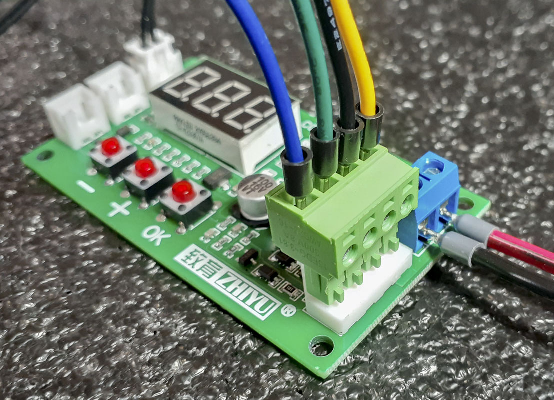
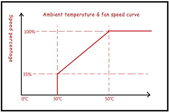
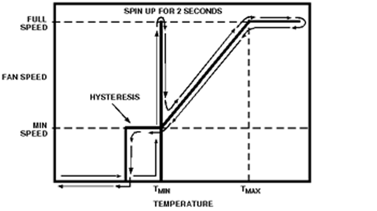
In testing this control, assuming the tach is reading correctly from the fan, the fan will spin 0 rpm then 720 rpm to 2550 rpm (for my 3000rpm fan?). The speed will remain at 0 rpm until setting ‘L’ is reached. There it will kick on at 720rom and start ramping up the speed as temperature increases. The speed will increase linearly to the setting ‘M’ where the duty cycle will be 100% and the speed (in this case) 2550 rpm. It will remain at 100% duty cycle as the temperature continues to grow. On the way down, the fan will reduce speed similarly on the same curve but remain at 720 rpm until setting ‘C’ (hysteresis) is reached when the fan is turned off below the initial engagement temperature. This, to keep the functioning from getting logically noisy.
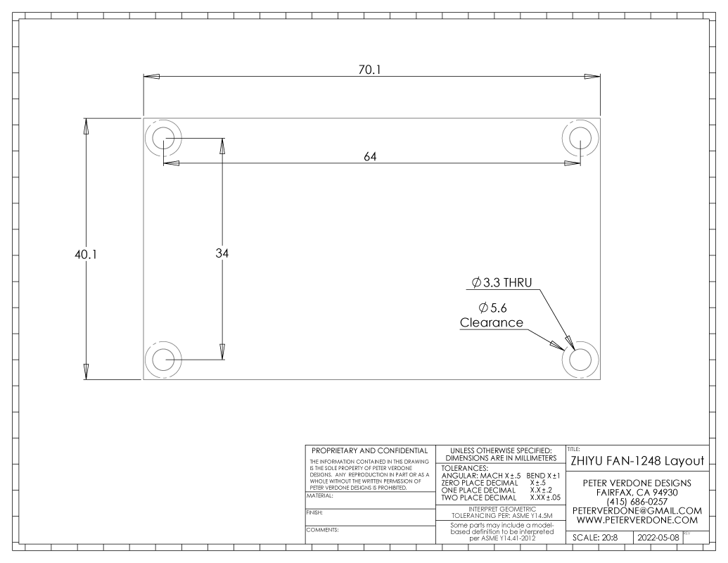
Now I need to make a mount to the DIN rail for this little board.
Now the fan actuation and duty cycle is controlled in a way that I can live with. The fan is incredibly silent even at the higher speeds. This is great!
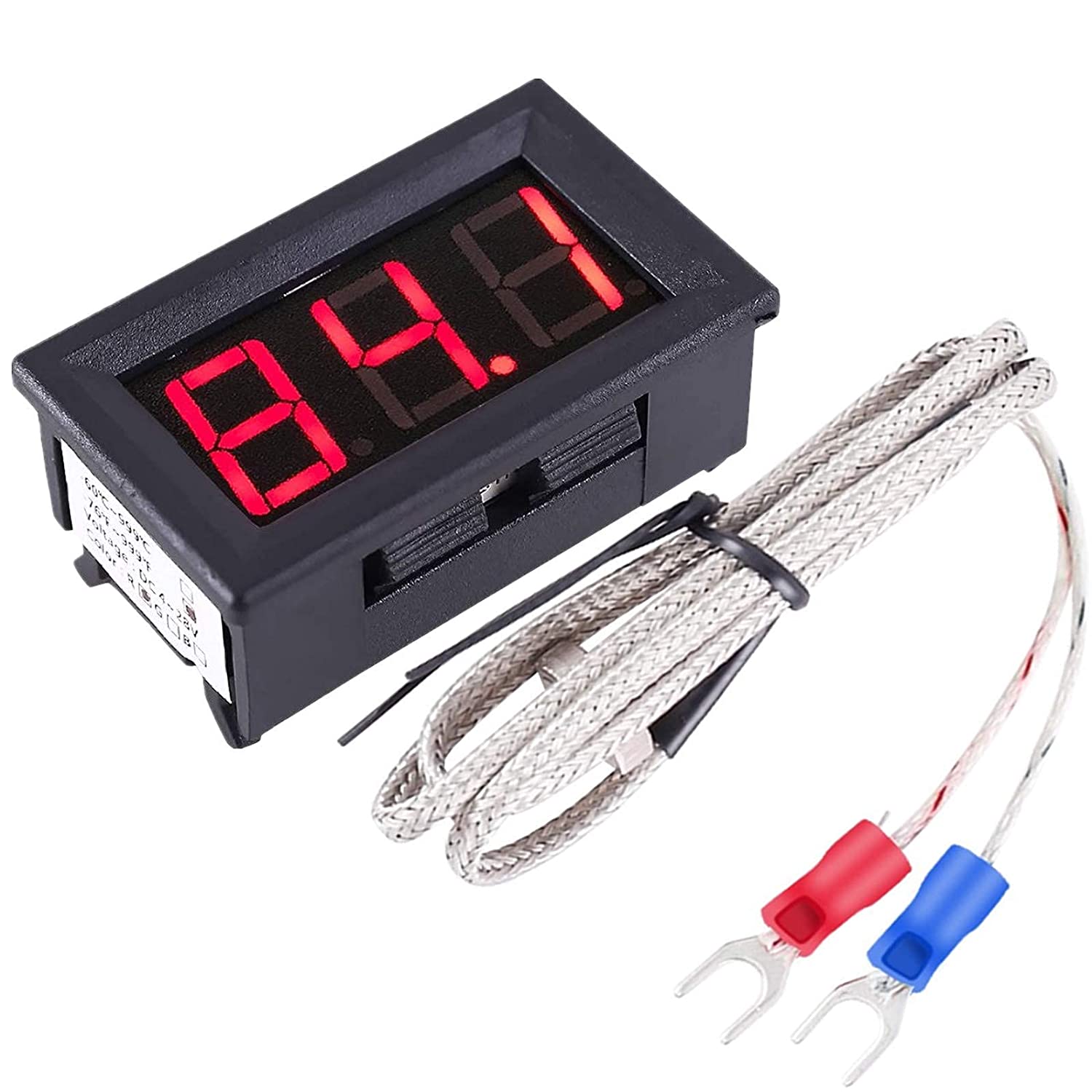
Since, I would still like a readable meter on the panel of the control box for the internal temperature, I found a small 24v thermometer readout ($15.99) with a Type K thermocouple sensor. This will tell me what is happening in the box even though the control is actually happening on a separate circuit at the DIN rail.
And that brings this section to a close. Fuck.