This is the holy grail of the plate style fixtures and is the third iteration of a bicycle fabrication fixture that has developed from modern bicycle design principles.
The 2020 Cyberdyne System fixture changed everything. By building a fixture on a breadboard surface, precise fabrication could be done with a lesser investment in tooling. The setup was magnificently rigid, accurate, and wildly flexible in what could be set up in position. Even so, it was a bit expensive to produce in materials cost, machining operations, and time invested.
The 2021 SKYNET fixture was an evolution of the Cyberdyne design. The goal being to bring the costs and complexities down to allow more people (with less money and skill) to get to build bikes. There were improvements made over the Cyberdyne and I would say it is a better fixture.
There’s always been a theoretical way of fixturing a bicycle frame for welding that would be simple, accurate, and precise that would require very little work to produce. Nobody that I know ever got that done. You see, complex fixtures can be very very simple we just muck it all up with our imaginations. In fact, it’s most often the math that makes getting them designed correctly a challenge.
I hadn’t been planning on producing a new fixture design. Starting another fixture surprised me. Last week after working out some weld table fixturing for another non-bike project, I was forced to look at the fundamental concepts as it was right in front of me. I couldn’t ignore this.
The WOPR spends all its time thinking about World War III. 24 hours a day, 365 days a year, it plays an endless series of ‘war games’, using all available information on the state of the world. The WOPR has already fought World War III, as a game, time and time again. It estimates Soviet responses to our responses to their responses and so on. Estimates damage, counts the dead, then it looks for ways to improve its score…
At the core of all of my recent fixtures is a Cartesian coordinate system provided by a welding table or optical breadboard. This gives us an extremely flat plane with pin holes precisely located at discrete coordinates.
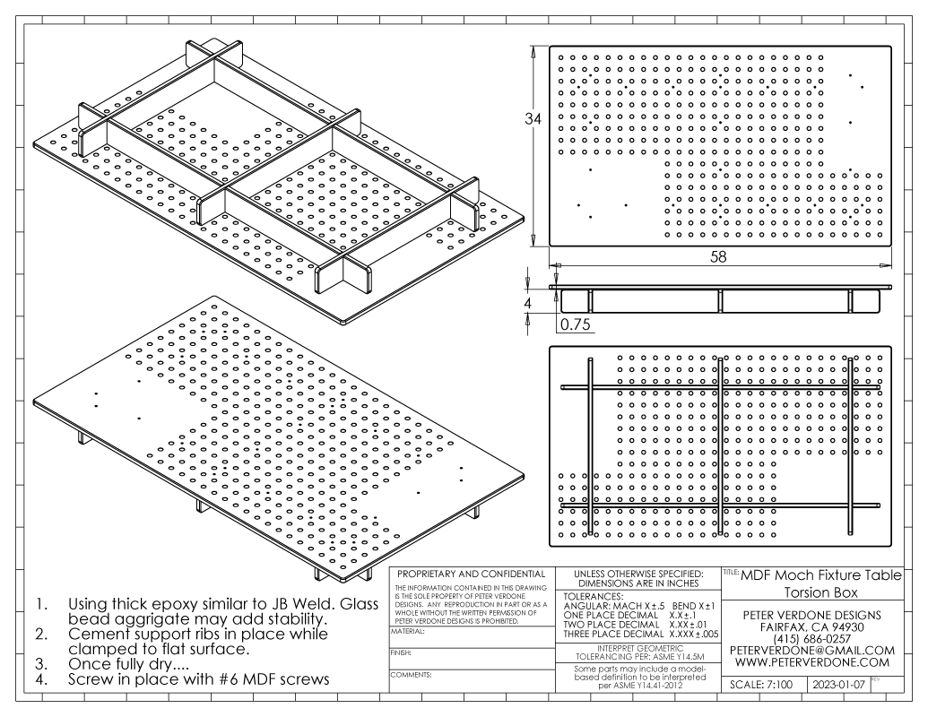
A simple MDF torsion box can be constructed with a breadboard raster. If money is a real object but you access to a nice CNC router, this is the ticket.
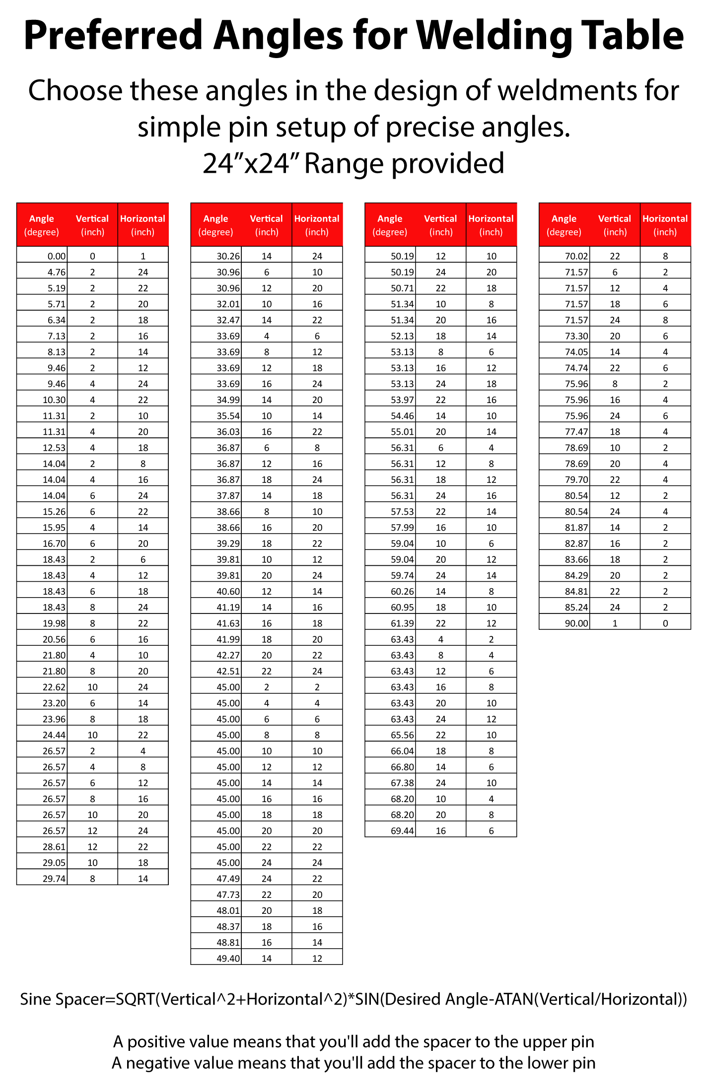
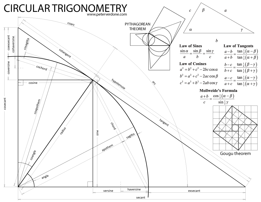
Most of the balance of the fixture design is in calculations. High school mathematics. Trigonometry and algebraic manipulation specifically. Anyone with a high school diploma can do the math for this and create the spreadsheet. In fact, using the definition of trigonometry below is all that should be needed.
The WOPR intends to leverage all of the previous work into an even more efficient math-based package. Rather than using a cosine bar on a sliding plate as on my previous fixtures, the WOPR uses table pinouts to construct an inclined plane that a sine bar is placed upon. At its core, this new fixture is amazingly simple. By relying on the raster of a breadboard and the placement of pins, we can construct inclined planes anywhere on the table. On those inclined planes, we can then build sine bars that, along with spacing, will position an axis at an exact location with respect to the origin (I use crank axis). This is very precise. Better, the tolerance stack up to get one of these axes in place can be less than 2 thousandths of an inch without much effort. This may not be obvious looking at it but that is what is happening. The only challenge was figuring out how to do it.
This fixture is adjusted by changing pin positions on the table and placing spacers between the pins and the components. These spacers produce the exact positioning of the axis and are very precise. This can be done via parallels, adjustable parallels, gauge blocks, or just milling or filing a scrap of aluminum to size.
The shortcoming of this design is that it isn’t adjustable with just a few screw turns. Block sets need to be produced for any change in the setting. That was sacrificed to get to this level of simplicity. Thus, it may not be the best design for when fixture setups are being frequently changed.
But, because of its minimalism, real modifications can be made to any part of the system without upsetting any other parts and just a few setting variables are changed in the spreadsheet. With this, you can get up and running with something that works well rapidly and then develop as needed over time.
It is intended that this fixture be used on a quality fixturable welding table. These should be in any fabrication shop. For many people, this is already in place. Some people might have optical breadboards in their world, that’s fine also as pins can be fastened to the thread holes. More, if you are broke, you can have a raster of holes cut in a sheet of MDF on a CNC router. The big change here is that it is irrelevant whether the table raster is 1.0″, 2.0″, 25mm, or 50mm. You can work with metric parts or imperial. It simply doesn’t matter as the spreadsheet will resolve everything to the format you choose. What makes this fixture so inexpensive is that it relies on a tool that we should all have in our shops or plan to purchase already.
I had initially drawn a setup beam for the head and seat angle beams. This was just a straight section that was significantly longer than the head and seat beams. This would allow me to spread the setup pins far apart while not creating a burden in making larger fixture parts. Really, any straight edge can be used to do this. A setup beam doesn’t need to be used and I’m not showing that. Pins and spacers are used directly against the the angle beams. This wouldn’t be as precise as using a setup beam but that may not be a meaningful gain in precision for all. The setup beam parameter remains in the calculations, should one be needed.
Another real improvement here is the radically minimal footprint that the fixture takes on the table. Once the angle beams and axle block are clamped in place, the pins, spacers, and setup parts can be removed from the table. This would allow for setup of other auxiliary fixtures for pivots, calipers, and any other desired tool. This also helps with torch clearance when tacking the underside of the frame.
After having used this type of fixture for the last two years I’ve experienced a level of confidence in my setups that I never had with other fixtures. I can validate almost any parameter of the frame or fixture quickly and easily before I weld. Whatever it is, a block, pin, and rule will let me measure it. I think that others will love that once they use it.
PVD WOPR Frame Fixture Package R202301071

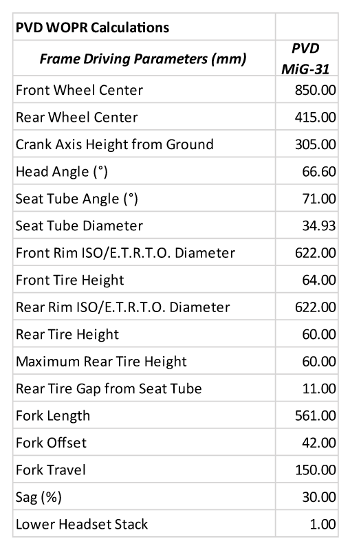
The spreadsheet inputs for the frame to be constructed are obvious to any bicycle designer. There are 17 parameters that will describe nearly any hardtail mountain bike, road bike, or all road bike in a fixture. A full suspension bicycle, moped, or motorcycle will deviate from this and I will not be discussing them here.
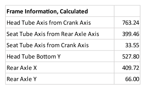
A few important descriptive parameters of the frame can be calculated from the initial driving parameters. These are used in final calculations.
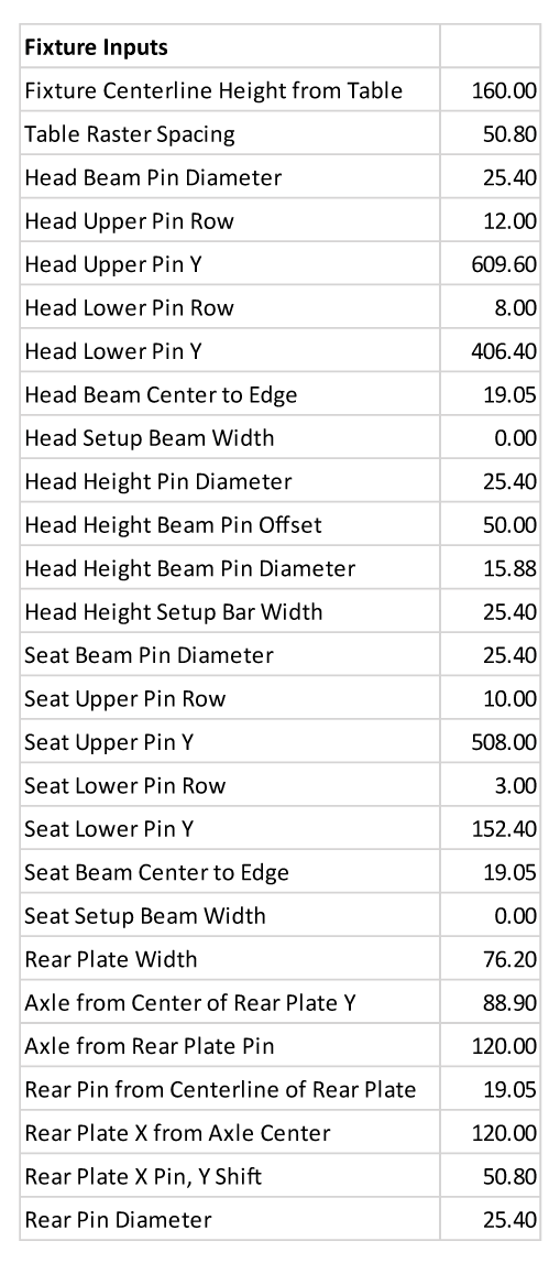
 A group of parameters describing your set up of the fixture is needed for the final calculations. These may seem like a lot but in reality, only a few of them will be changed, if at all, when in use. Those primarily being the pin rows chosen for the head and seat beams. This makes it possible to move pins out of the way if a particular area on the table is needed for other fixturing. Generally, it is preferred to spread these as far apart as possible. Any of these fixture inputs can be changed and this gives the user a great deal of ways that they can change the construction of the tool.
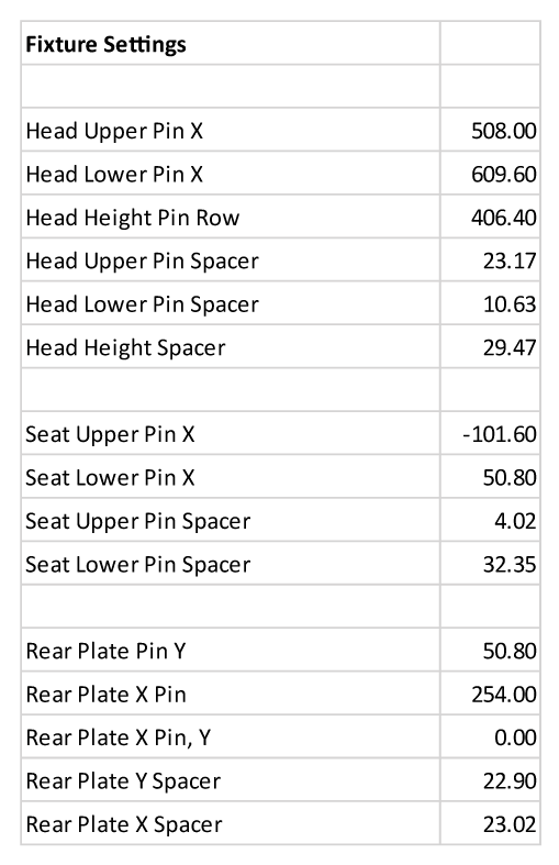
The fixture setting are then calculated. Pin locations are provided as well as spacer blocks.
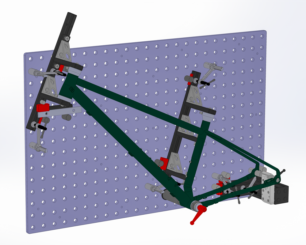
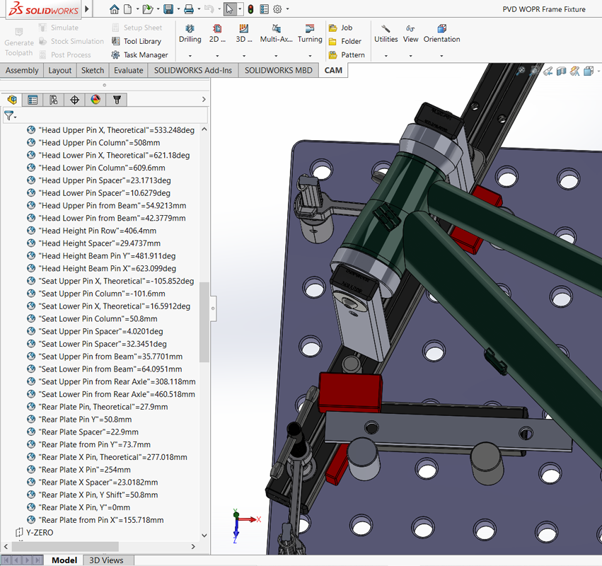
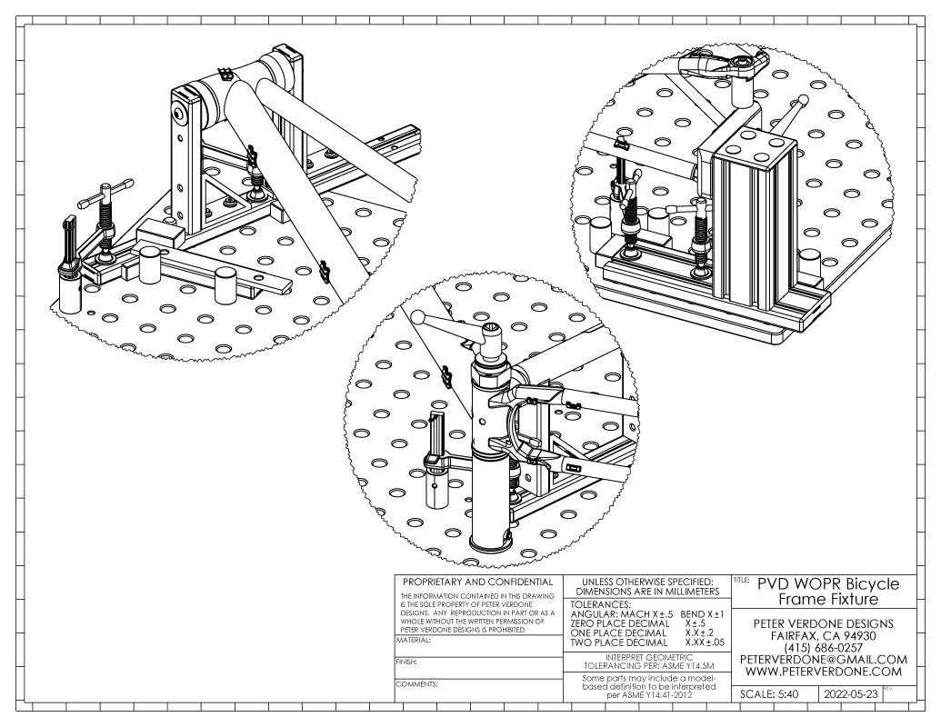
This graphic shows the fixture set with everything in place. I’ve dimensioned as much as is meaningful to help folks see what has been described in the spreadsheet.

To be clear, I’m showing images generated in 3D CAD to prove that the spreadsheet values are correct. The spreadsheet IS the calculator for this fixture and that tool is available to anyone. Even in my Solidworks assembly, I am doing calculations using the same formulas I developed in the spreadsheet.
PVD WOPR Frame Fixture Package R202301071
Some different perspectives to help understanding.
I’ve chosen to design this tool with 8020 extrusion. Another might use other stock that is more continent for them. Most of the parts can be made in different ways and in different sizes with just a spreadsheet variable change made to account for the difference.
Several BuildPro Inserta Clamps (UDN5150) are used in the fixture. The cost of these add up at $19 each but they are incredibly useful for a huge number of other projects. I show the 6.5″ version cut down to 125mm high for improved maneuverability over the table. There are much cheaper ways of clamping to the surface of whatever breadboard you are using but I’ll let those that need to focus on that. For me, this is the wisest direction to go.
I’m posting some very rough prints now so I can get this made public quickly. There are plenty of issues with this package and will be fixed and improved over the next few days. It will end up as nice as the SKYNET plans. Cost estimate for you to produce your own PVD WOPR: just a few hundred dollars.
PVD WOPR Frame Fixture Package R202301071

Simple takes a lot of work. Simple is hard. To explain why it’s taken three iterations to arrive at something so minimalist, an important engineering principle is perfectly encapsulated by this Blaise Pascal quote from 1656:
“Je n’ai fait celle-ci plus longue que parce que je n’ai pas eu le loisir de la faire plus courte.”
Another reference is what mode I’m working with here. In the clip below, I’m giving a lecture at PBE2021. I’m discussing engineering modes. This fixture is firmly into StG44 country. Please note, I say “walking fire” when I should have said “intermediate cartridge”. My mind was racing and I made a mistake.