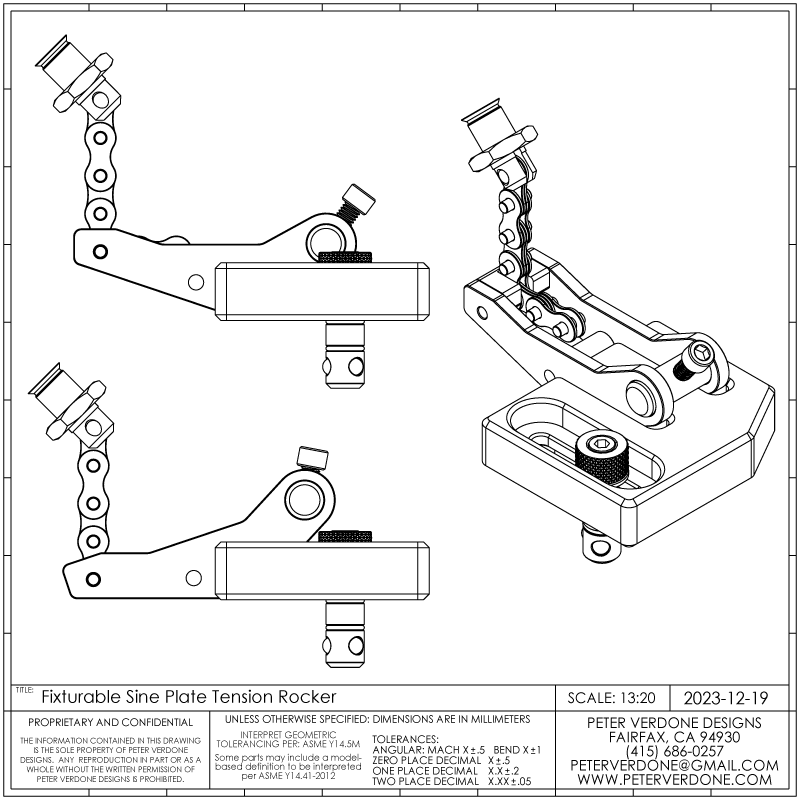
This is a project that I had been working on last year. It’s a fixturable sine bar for use on fixturable fabrication tables. Sadly, I got distracted before finishing it but it might be at some point. For that reason, I delayed posting on it until now.
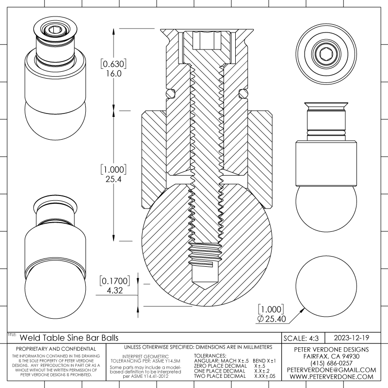
With a good design and an hour at the lathe, I was able to produce the several parts for this useful setup.
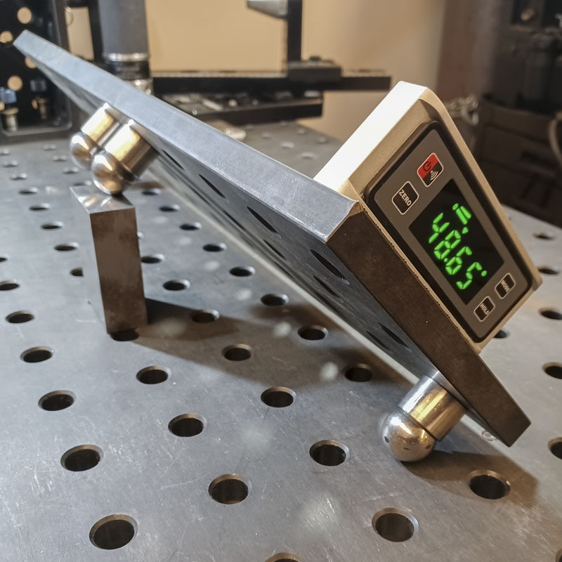
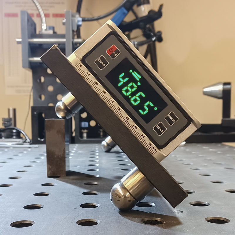
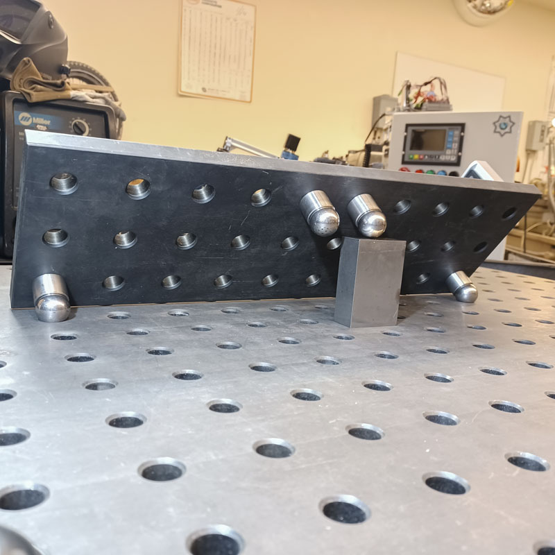
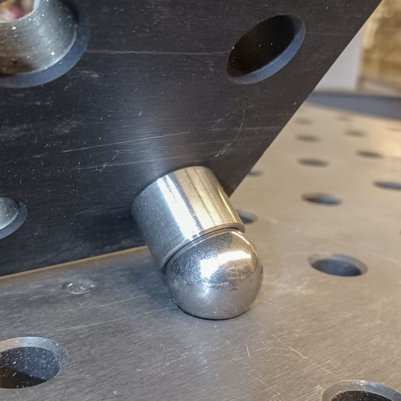
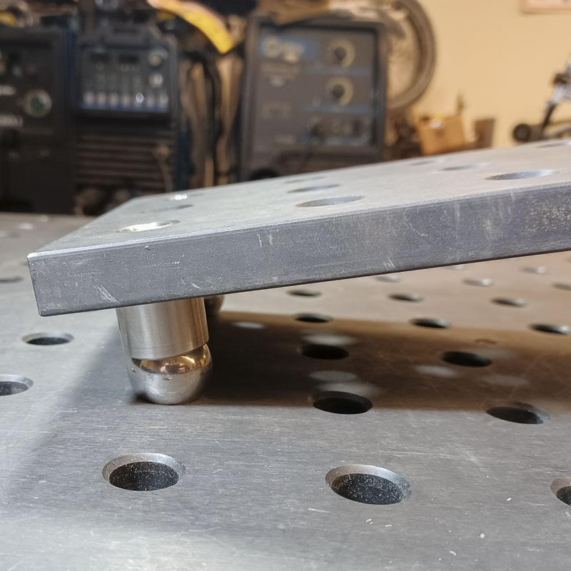
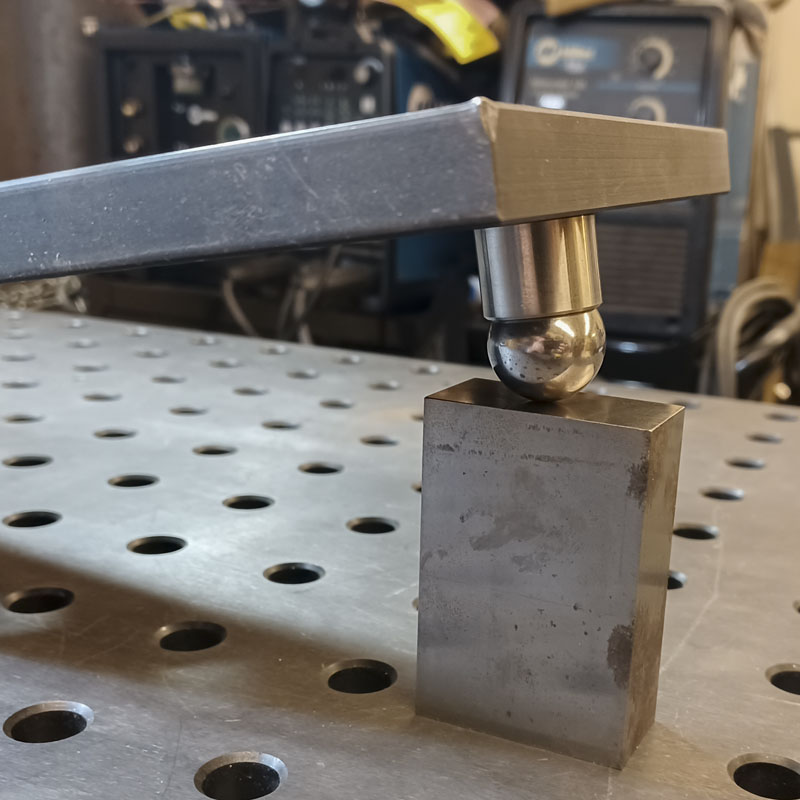
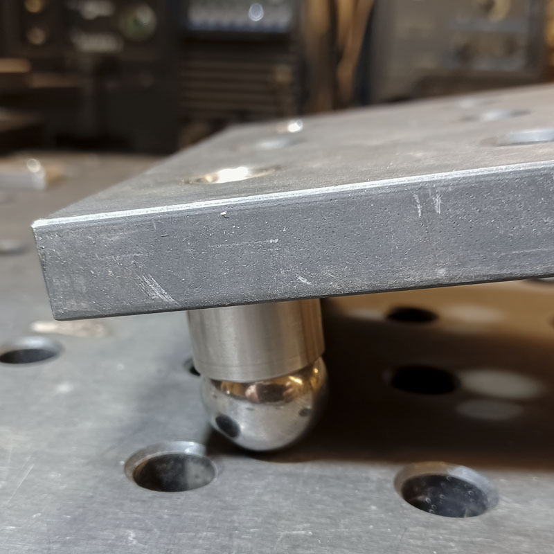
One of the very cool things about this design is that the balls will index on the table if need be. Of course this will lower the tangent of the ball below the table surface, making setting the height for the angle less straightforward. Now, that offset needs to be calculated and factored in.
I know that the the opening of the chamfer that the ball will be sitting in as it was experimentally arrived at 0.7542″. This is very consistent within a few fractions of a thousands of an inch across my sample. The taper lead for the table pins is extremely consistent as they are machined at the same time as the holes using very expensive and high quality methods. There may be some inconsistencies but I’m willing to bet that they may account for just 0.002″ at most.
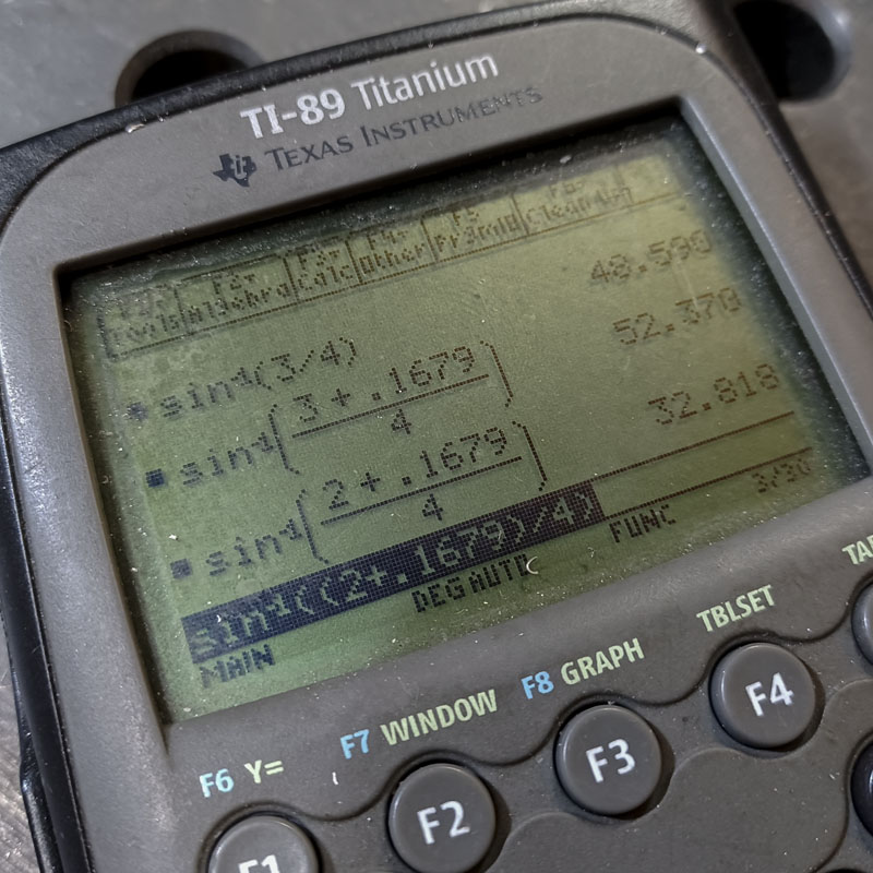
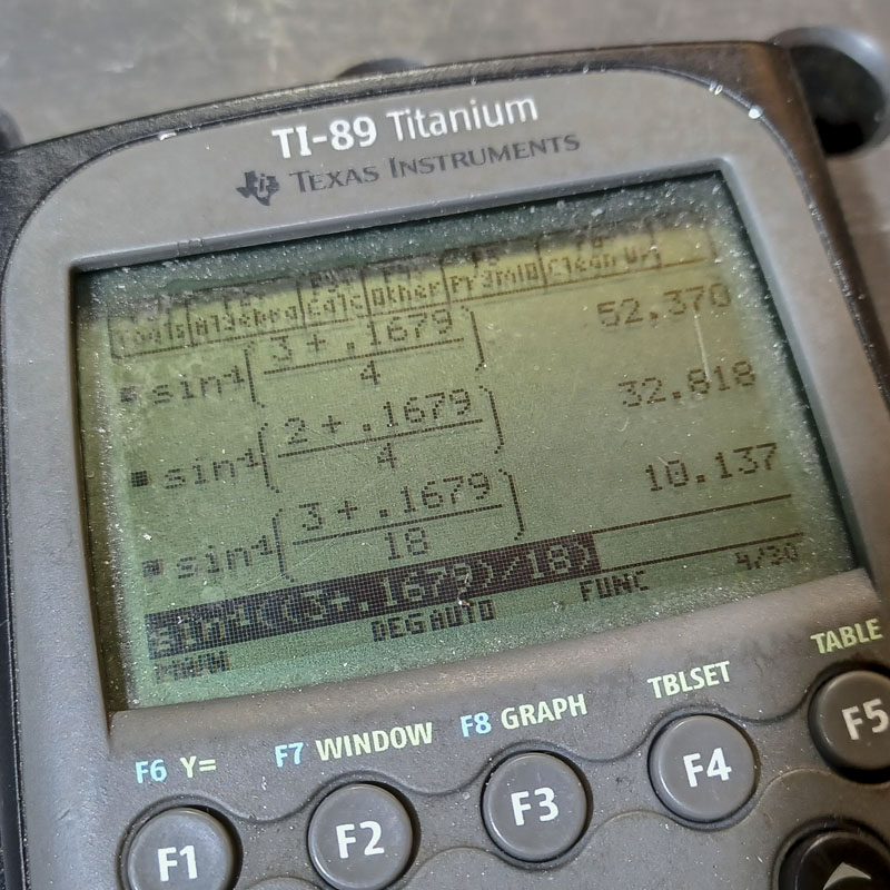
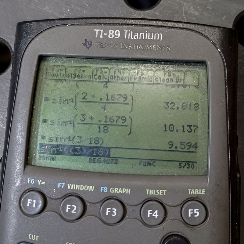
The formula is simply:
= “Ball Diameter”/2 – SQR((“Ball Diameter”/2)^2 – (“Ball Diameter”*SIN(“Taper Angle”/2)^2)/4) + (“Taper Opening” – “Ball Diameter”*SIN(“Taper Angle”/2))/2
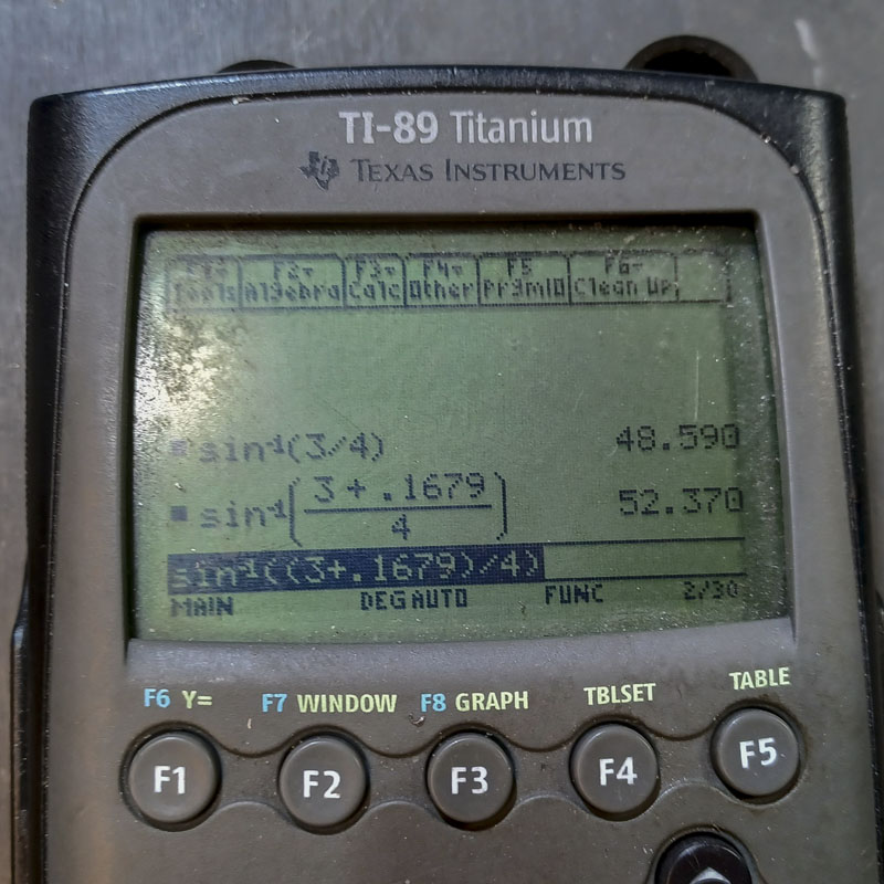
= 1.000″/2 – SQR((1.000″/2)^2 – (1.000″*SIN(90°/2)^2)/4) + (0.7542″-1.000″*SIN(90°/2))/2
= 0.1700”

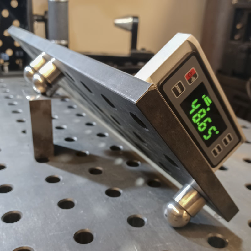
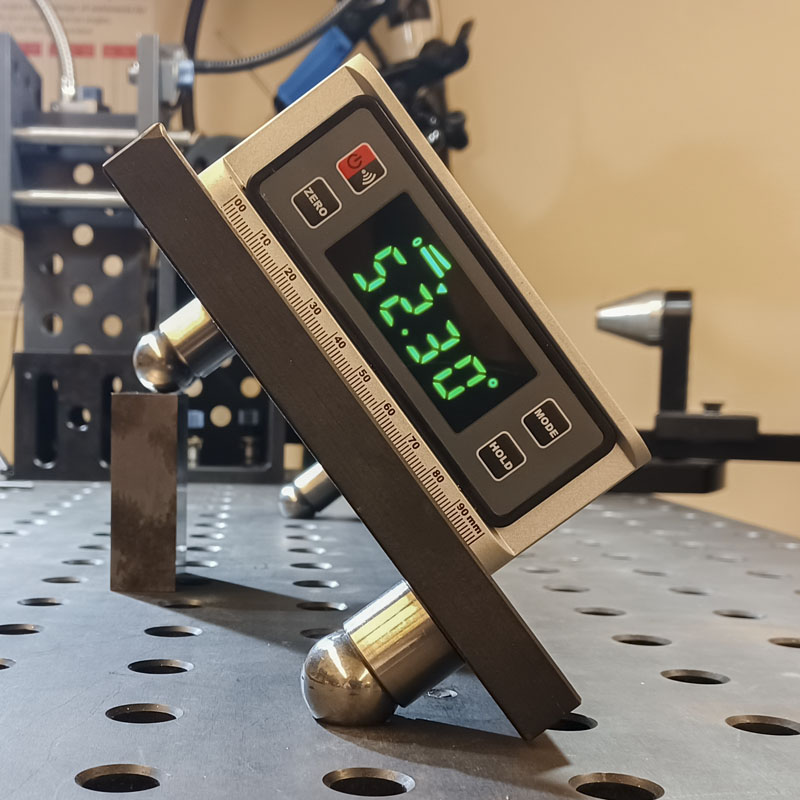
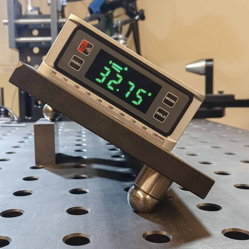
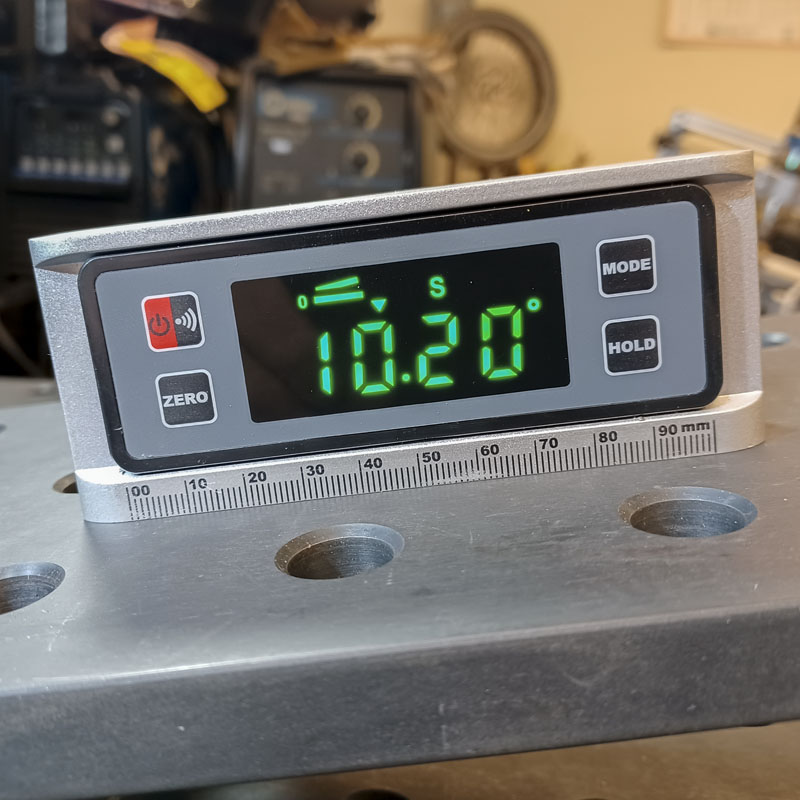
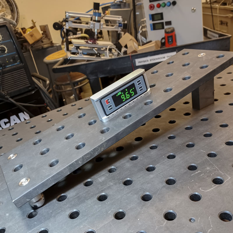
We can see that this is working fairly well. Looking at the two situations for an 18.0″ radius, sitting on the table versus sitting in the taper is very close to the same measured difference. We are very close to the resolution of the measurement device. I have even gone back from my initial photos to check the setup using a far better method.
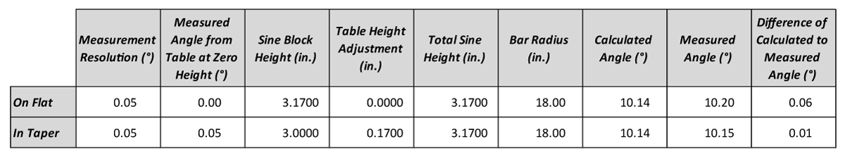
The deviation from each other will have to do with a host of factors; flatness of the plate, exact placement of the balls, ball system height, accuracy of the measurement, chamfer deviation from theoretical, etc. Still, we are talking about less than 1/2 of 1/10th of a degree for a setup that I just tossed together to get photos. That’s a pretty useful system.
There have been criticism that this is a kinematically indeterminate construction. This means that it is theoretically impossible for the balls to locate in exactly the same way every time the plate is placed on the chamfers. I will agree that this is true. Lucky for anyone using a fabrication table in a shop, this construction is far more accurate and precise than any other easy option for producing a very high resolution of angles registered to the table. It is well above the a level of work that most machinists work at, let alone a fabricator. A correctly defined construction would be far more expensive, cumbersome, stack more tolerances, and (technically) be no better.
The part that hasn’t been finished is the tension rocker. It makes use of a special type of chain that is used in fixturing and wrenches. This simple tool will work in most of the angular range and pull the plate down to the table with significant force. I had wanted to do this before this post but I’m tabling construction for a bit longer. One day…
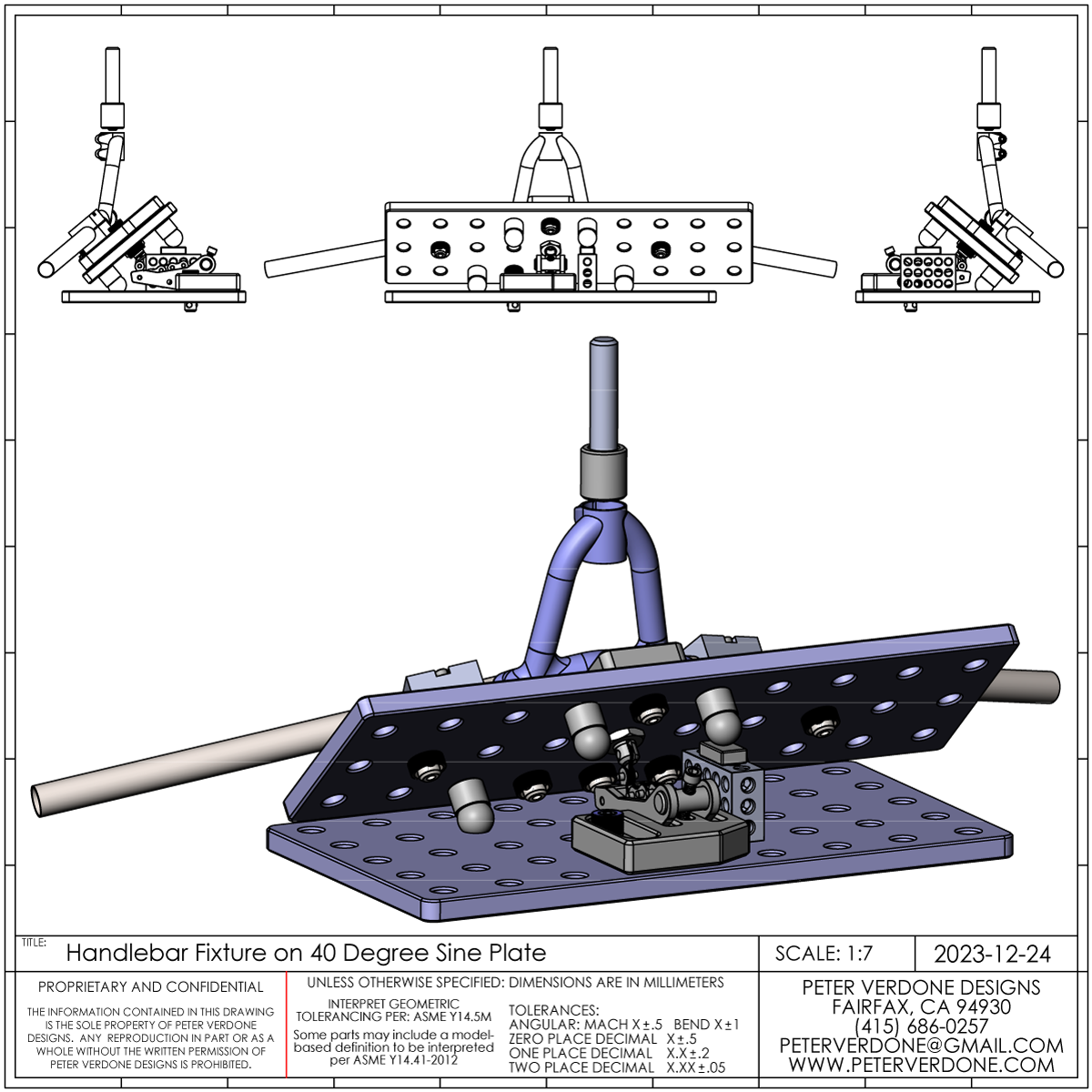
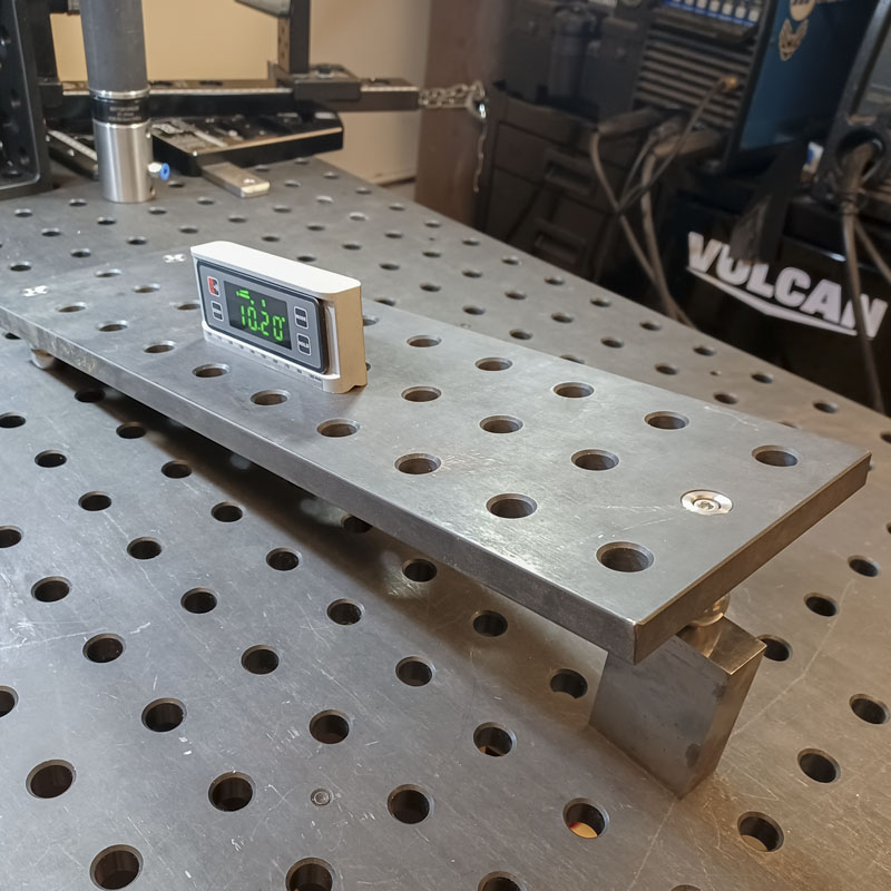
Here is a practical example of this sine plate in use. Holding a handlebar construction at an exact 40.00 degree angle off the table. Now the steerer is normal to the main top.