
In my last post about the kinematics that I worked out for the new motorcycle, I referred to something in the choice of ‘countershaft’ sprocket location that was interesting. Now we are going to look at the anti-squat and countershaft position. This is something that I discussed years ago regarding idiocy in the bicycle world around the subject but now I get to become a target myself.
Like many nerds of the subject, I thought that I had a good understanding of the relatively obvious topic of placing a countershaft. Simple enough, move the countershaft to the right location relative to the trailing arm ground node so that you get the anti-squat amount intended. Surprisingly, it’s not really like that in practice. The devil is in the details and those aren’t what you might expect.
I mis-spoke in the video about energy density. I said “We need energy density to be at least cut in half if not more. If that happens everything becomes truly viable.” Instead, I should have said, “double”. This should be an obvious trip over my words.
While there may be circumstances where a designer has liberty to move the countershaft sprocket position in the system, it’s simply not possible in most situations. The practicalities of clearing swingarm bodies, gearing options/needs, and even the amount of wheel travel that is in the system cause major problems that force us to make painful choices. It gets even worse if the motor layout makes everything harder.
Below is a diagram of the trailing arm positions in the several compressive states; initial (0%), sag (30%), mid (50%), and final (100%).
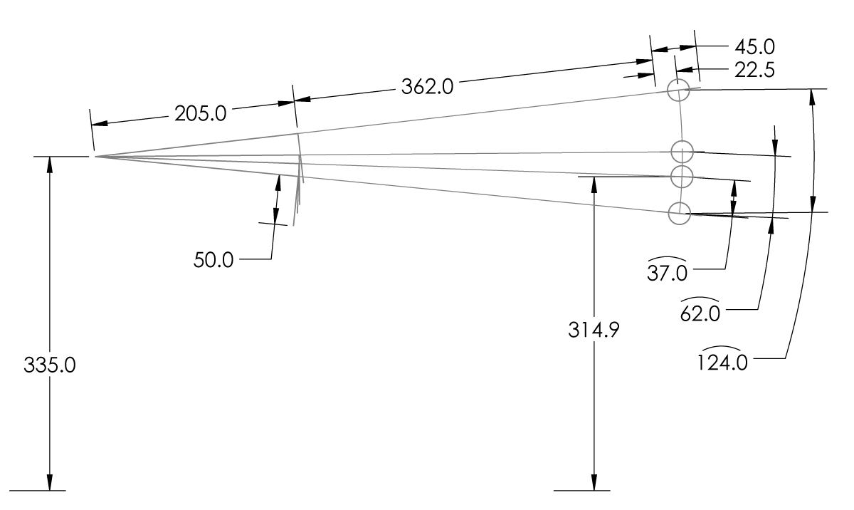
You will notice that I’m using a very particular method of defining travel. I’m not using vertical displacement or point to point. It turns out that in the case of the motorcycle with single pivot swingarm, the radial displacement may be the most advantageous. Why? This get’s the the fundamental goal of the kinematic system, we want to linearize the motion of the wheel to the damper. The wheel is moving about an arc. Define it as such. The radial 124mm of travel. That being twice the damper displacement of 62mm. We may want vertical or horizontal components for other reasons later but we need to start with the wheel moving radially.
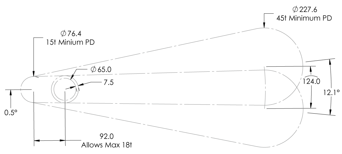
We now start looking at laying out the practicalities of the system. The trailing arm that I’m using takes up 65mm of space surrounding the line from the ground node to the rear axle. The countershaft sprocket sizes will range from 15t-18t and the wheel sprocket from 45t-54t, with initial being 16/54. To allow the countershaft sprocket of 18t, it must be a minimum of 92mm from the trailing arm node. For reference, the chain is 15mm tall.
An interesting thing happens. If the smallest sprockets are chosen, there is only one location that the countershaft sprocket can be and that is along the plane formed by the angle of the trailing arm at mid-travel, 0.5°. The chain will be gliding right at the edge of the trailing arm at the limits of wheel travel.
While this demonstrates an optimized system, another that wasn’t as carefully chosen could produce a condition where the chain is attempting to saw the trailing arm under power in a range of wheel travels. That’s really bad.
I also know that I should never attempt a 14t countershaft sprocket or a sub-45t rear sprocket.
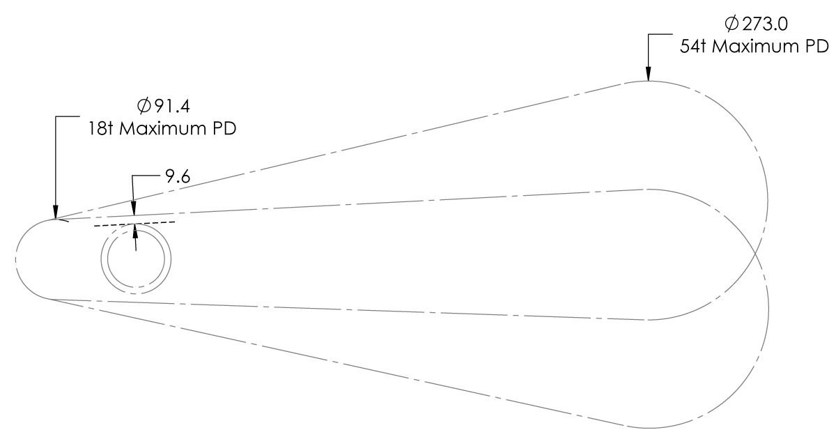
If the largest sprockets are chosen, the chain moves to a safer distance from the trailing arm but only just. Given my choices, that 9.6mm from the trailing arm. Were we to offset outward 7.5mm, we’d have an important boundary for chassis parts in the area of the chain.
This gets back to my decision to define the system around radial displacement of the wheel. Since mid-arc becomes so important in the placement of the countershaft, shouldn’t I define the system that way? The math gets far easier, I can quickly lay out geometry, values start making more sense. This is what motivated me to make the change.
Obviously, we see issues even on real production motorcycles regarding this. Some dirt bikes will have the chain folding over the trailing arm node when the wheel is at full extension. This is a decision that was made in engineering. Engineering is the art of wanting everything and getting nothing. The real world demands of more wheel travel than the system should allow and the understanding that maximum power may not be going through the chain in some locations as well as wear parts that will be expected to be changed make us see odd things.
With my chopper, I can just reduce travel to help keep it clean. It’s a chopper and 124mm of quality suspension travel is far more than most in this class dream of…remember… I said quality.
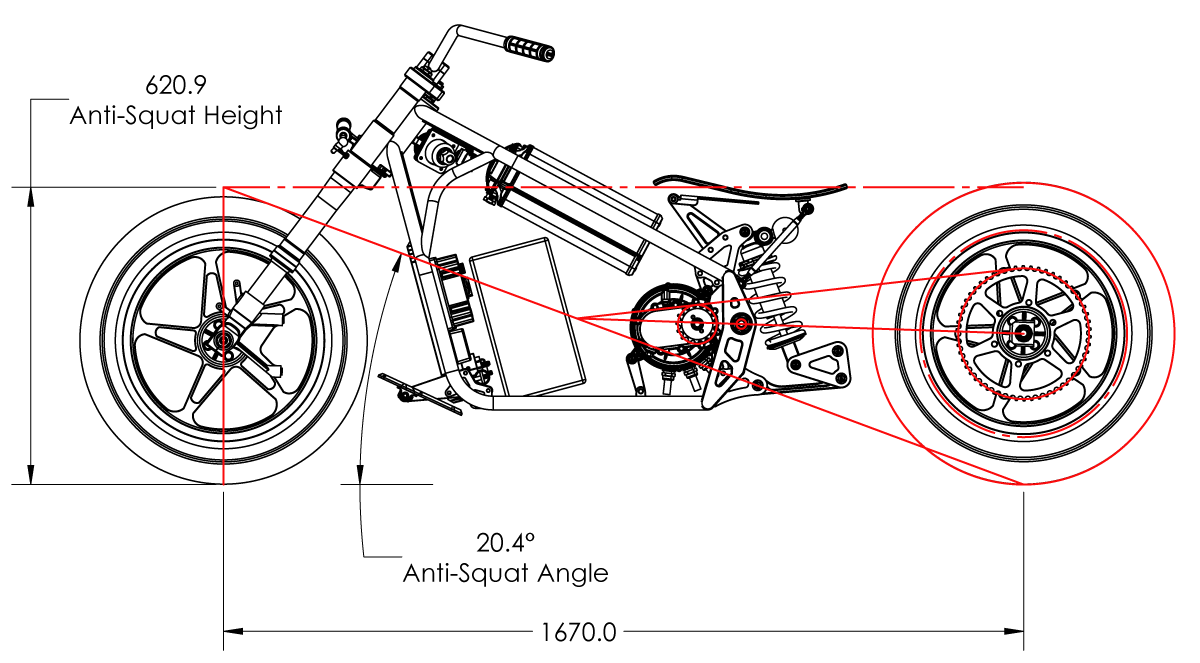
With the countershaft placed, we can look at the anti-squat diagram of the system. The gearing is 16t/54t and the rear wheel is at 30% sag (37mm), the front wheel is at sag. The anti-squat angle is 20.4° and hits the front axle vertical at 620.9mm.
Anti-squat is important in the design of the rear end. Under acceleration, the COM desires to rotate about the rear contact patch. As this happens, a huge amount of weight transfers to the rear of the bike, through the rear damper and into the rear tire. Since weight this is also going through the rear spring it will compress under the additional load. This lowers the rear end of the bike. This action changes the geometry of the front of the bike (thus handling) and leaves less of the shock to track along the ground in compression. To mitigate this, we want some ‘anti-squat’ engineered into the driveline to fight against this compressive loading. Too much and the system is forced to extend under acceleration and the tire is not able to track the road surface. Just the right amount of anti-squat will keep the bike handling predictably in most on-power situations with the best traction given the alternatives.
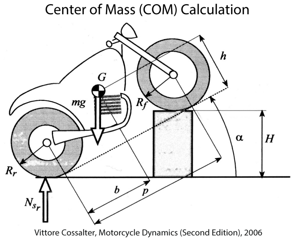
h =cot \left( \arcsin \left( \frac{H}{p} \right) \right) \left[ \frac{N_{S_r} p}{mg} - (p - b) \right] \ + \frac{R_r + R_f}{2}Mapping the system helps tell me if I want to change the anti-squat angle, the primary method is by changing the trailing arm ground node height. It is not in altering the countershaft placement.
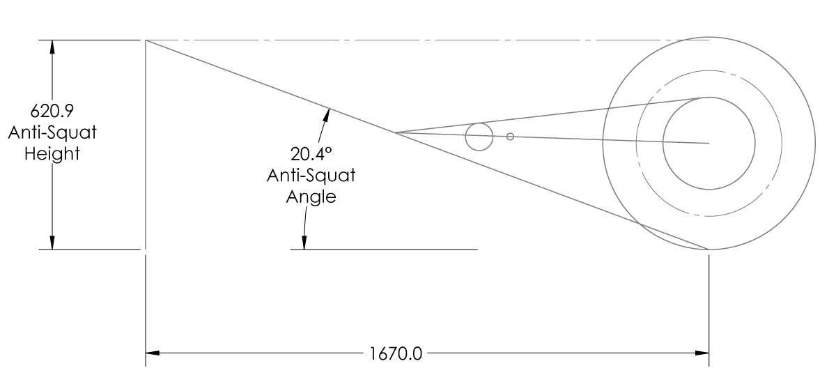
How does this fit into the shape of the motorcycle? If the COM of the system ends up above the tops of the tires, the bike will just slightly squat. If the COM is below that, the system will just slightly jack.
I would have better predictions of where the COM would be if I was working in a serious production environment but as a hobbyist, I’m going to have to guess for the first bike and refine on the next when I have better data.
Metal work starts next week. Tubes are here. Water cuts should be done. Maybe something can get done.