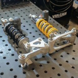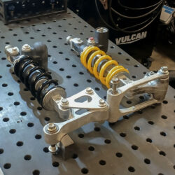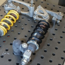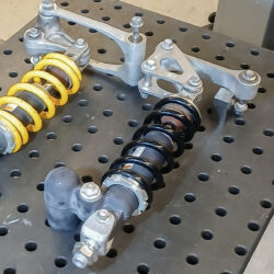
I’m doing a bit of R&D for an eCruiser project. I’m an old man now so sportbikes aren’t my goal and dirt bikes will have to wait until I move from the bay area. This post focuses on the rear end kinematics.
The last bike I was riding, a 2014 Honda CTX700, was an awesome step to the old man world of motorcycles. A relaxed upright but low position, swept back bars and small forward floorboards. It was so comfortable. More, the DCT and ABS were a joy. Sadly, that got totaled in a crash at the Golden Gate Bridge toll plaza when I was cut off by a crazy driver a year and a half ago. I’ve been off the motorcycle since and really need to get back for my sanity. Buying a beater Shadow makes sense. Making something cool is more exciting.
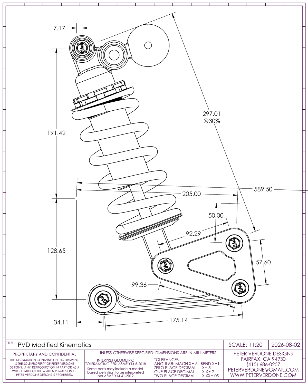
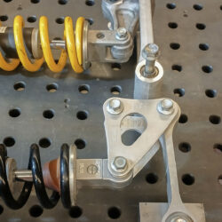
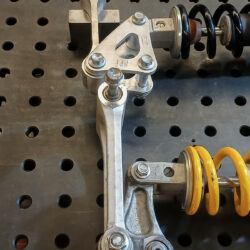
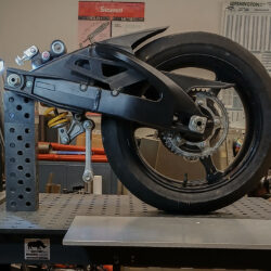
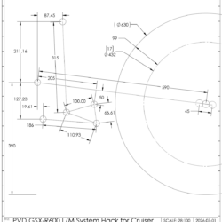
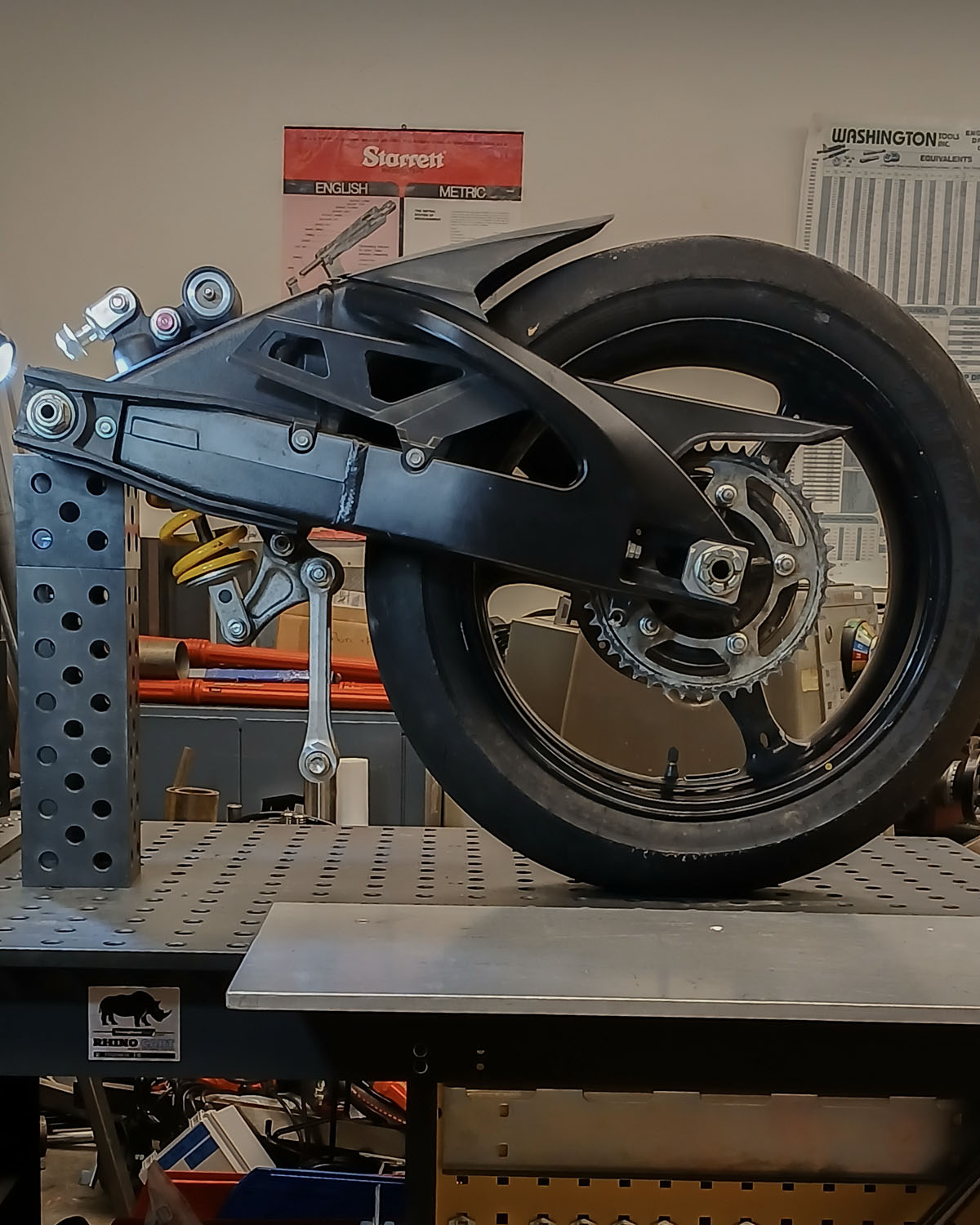
I’ll be using a front and rear end from a GSX-R to produce the bike with a chassis of my own design. To do this, the geometry of the rear end is going to be modified to fit the new design. The ground nodes will be changed as well as the tension link and bell crank. In many ways, I need to completely re-design the suspension system with a few constraints. This is not easy.
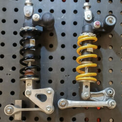
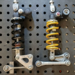
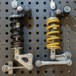
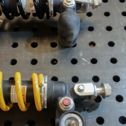
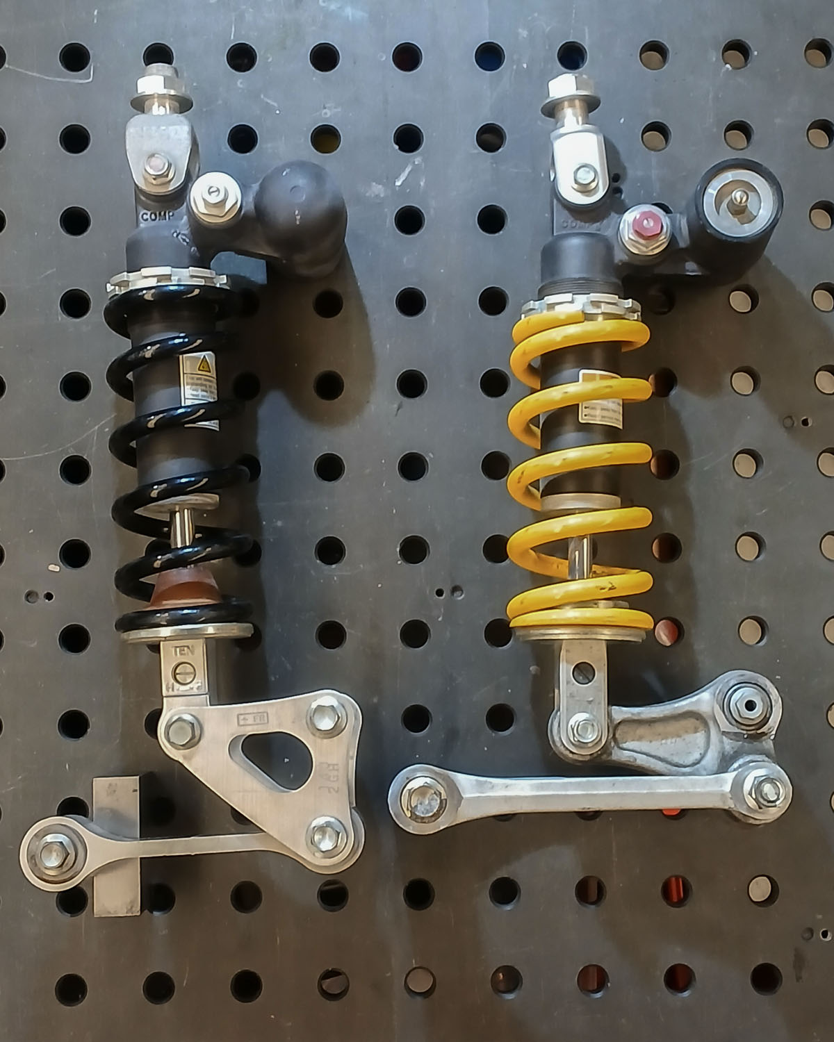
Starting this is helped in that I have a K8 GSX-R1000 front and rear end that I can use. This is leftover from a 20 year old zombie project. I had to dig around in the garage but I managed to find all the parts. The parts are so nice there’s little reason to use anything else. I just need to optimize them for this use.
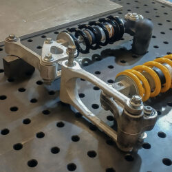
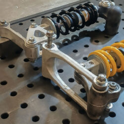
Frivolously, I also obtained a L/M rear end to play with as the linkages are arraigned differently allowing different solutions. It makes tension links and bell cranks far easier to make. I’m investing more into getting this right than I was initially expecting.
The difference in the K and the L/M rear ends is primarily in the linkage arraignment. The K is far more compact and allows for more geometry range. It’s a pain to make the parts when I do custom stuff. The L/M is a ton easier to make parts for but it takes up more space and has some limitations. Using the L/M will force a bent tension link.
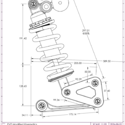
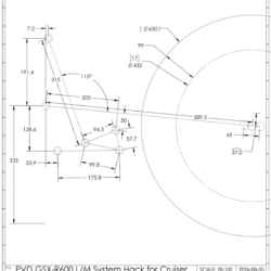
I modeled the parts of the system in SolidWorks. Nothing too elaborate in detail but precise in measures. This would allow me to figure out the best locations for the chassis trailing arm ground node, tension link ground node, and upper damper ground node. In modeling space, I can establish geometries that function mechanically as prescribed.
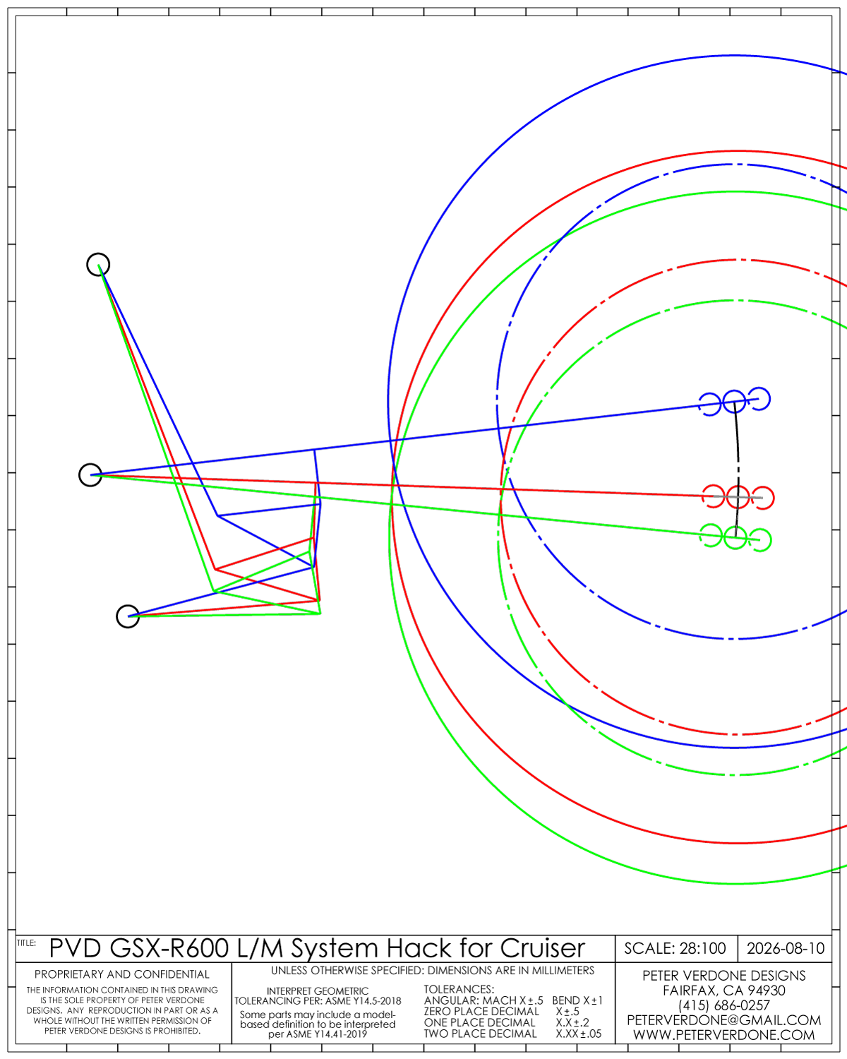
It took a while to understand what the Suzuki engineers had done with their OEM design. Once I had that, I was able to really start moving parts around in space. I didn’t have complete freedom, still using the stock swingarm and shock and the target leverage ratio curve. I also wanted to keep the saddle low and have the anti-squat work with the lower center of mass that is expected.
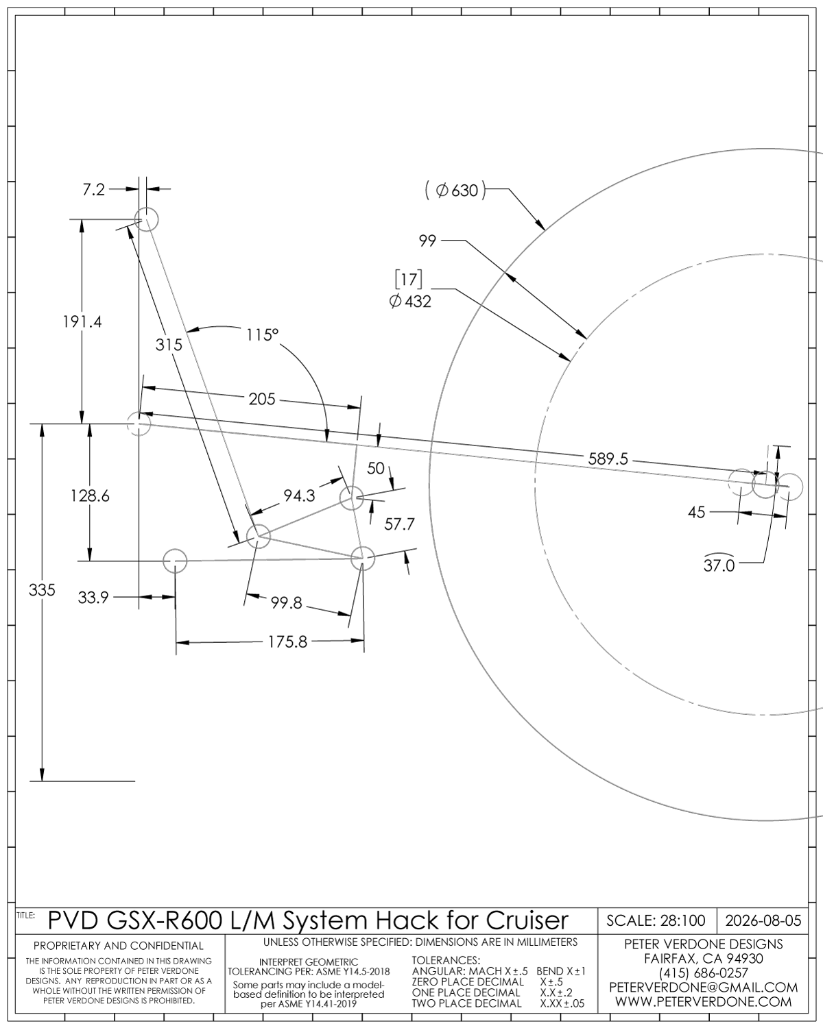
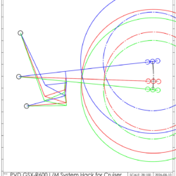
Getting valid parameters starts with the CAD sketch for bump and droop.. This proves that the locations I’ve chosen work geometrically for the defined parameters.
I’m moving some things around for space and decreasing travel from stated 130mm (undefined) to 124mm (radial). I’ve found in this that (for single pivot motorcycles) discussing wheel travel in radial terms makes the most sense. I will elaborate on this in a later post. For now know that my discussion is for wheel movement around the circumference, not the vertical component. Remember that the vertical component is calculated simply at the end.
Optimal fit is hard in a constrained system. I also don’t have a lot of influence on most of the system, like swingarm measures. I would prefer more travel but would need a longer shock. This one is 315mm with 62mm stroke. Also, my trailing link ground node is 335mm from the ground at sag. I’m hoping that this delivers a meaningful level of anti-squat. I’ll save bigger changes for revision two.
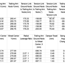
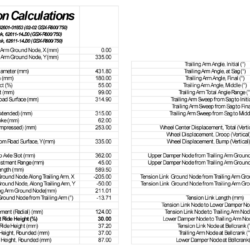
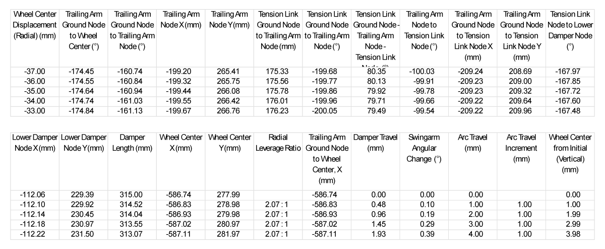
To evaluate how well those systems work in terms of suspension kinematics, I could go down two paths, a SolidWorks motion study or a calculator. I prefer calculators. The math of the calculator is similar to what I did for the Transition Smuggler in 2023. The shame about this method is that it goes from the wheel to the shock and I’d prefer the other way. That is hard. Let me know if you have a way.
From here, I can enter them into the calculator. These are the driving parameters and a few fixed calculations. It’s a challenge to figure out the correct naming conventions to use for this work. I want to find the right way to discuss this so that folks can understand precisely what is being said. If you see a name that should change, let me know.
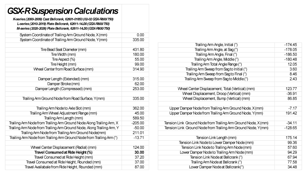
So many steps to get to the end. This takes focus and time to figure out. I’m still cleaning all of this up. I wish I was better with math and serious engineering kinematics.
I can now get some visual understanding of the behaviors. The ‘curves’ as they say.
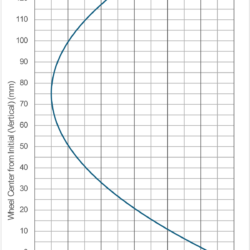
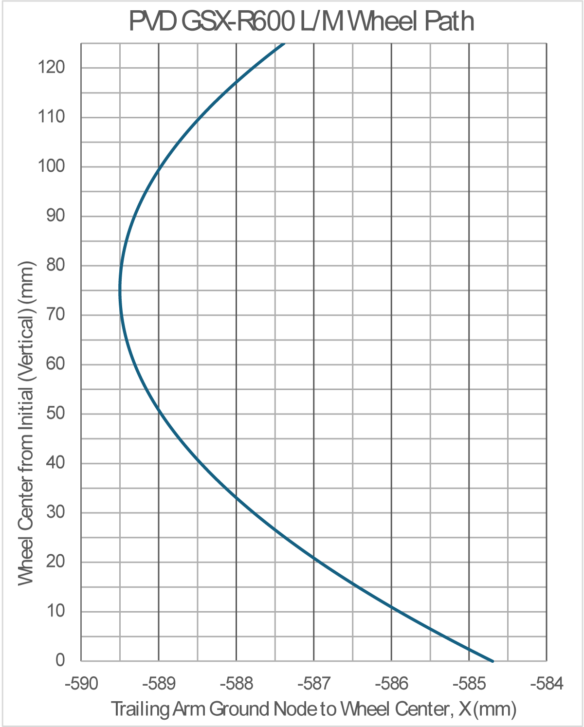
The wheel path. It climbs up and back then forward. This is obvious since the trailing arm node is only just above the wheel axle at initial. This isn’t desirable, it would be better if the wheel never had to move forward but getting a low saddle is forcing some packaging decisions.
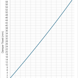
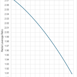
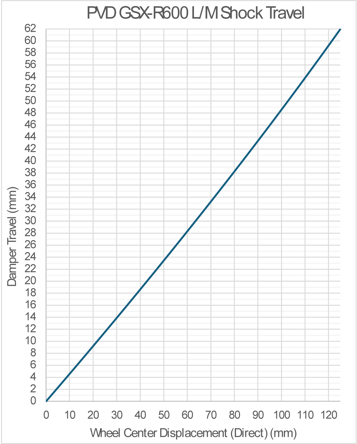
A simple plot of the shock to direct travel of the system. It’s always funny how straight that this looks compared to the leverage ratio but that’s to be expected. The leverage ratio curve plot is designed to make very small changes look big.
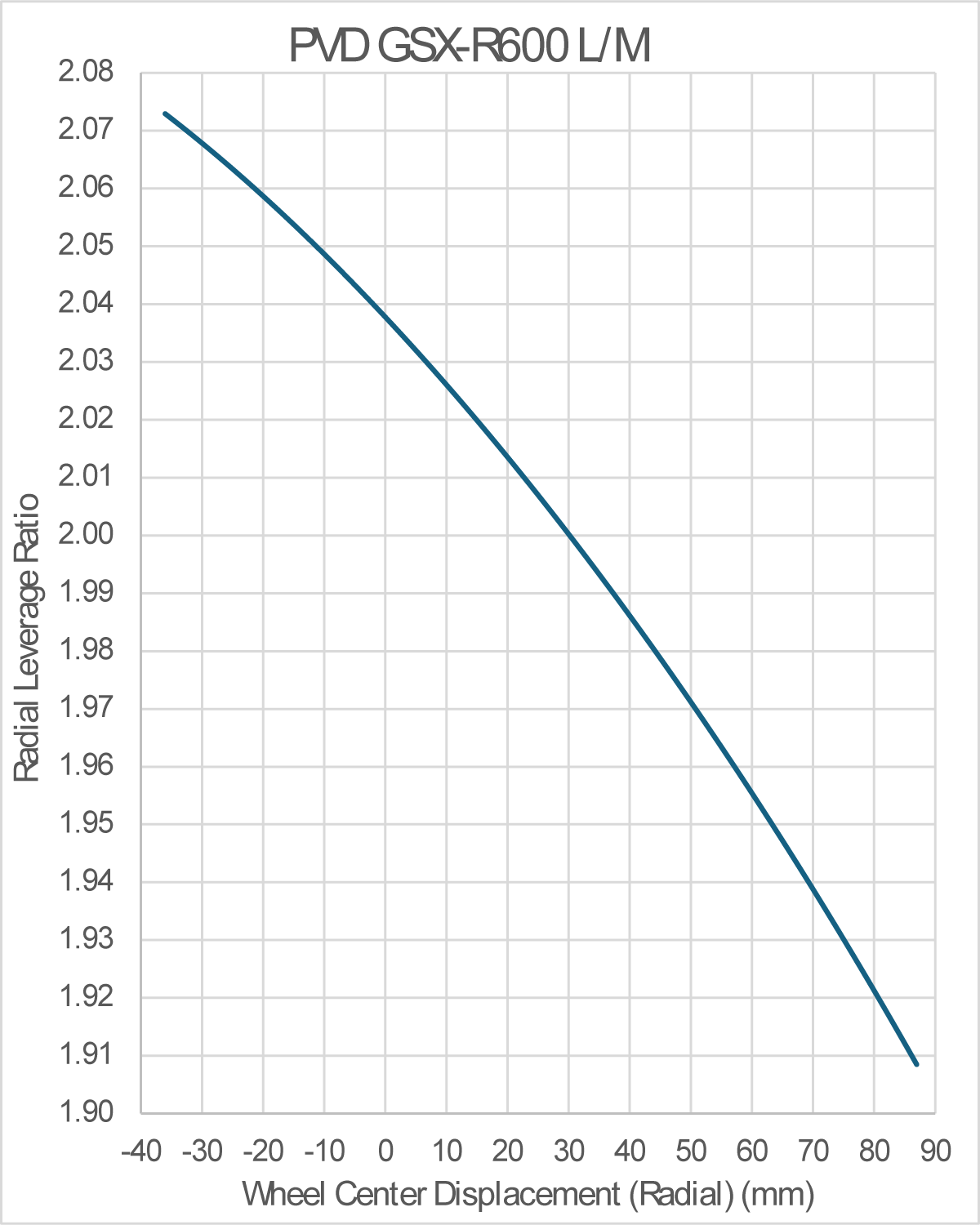
The leverage ratio. I want some progressivity in the action but not crazy. The bike should feel cozy and smooth with some margin of safety for bottoming when I’m on dirt roads and rallying hard. 2.07 to 1.91. Not linear but not super progressive. There is a bit of brute force and reality of special relationships so it takes a while to get things working well.
Because there is little discussion about the behaviors that are changed by any one change in this system. I do have to guess and hope. Anyone with a better understanding of this stuff should reach out to me. I have a lot to learn.
Next task is to calculate the countershaft sprocket location with the anti-squat values that I anticipate. I probably could have gotten this done for this post but I was a little burnt on math for right now.