Making things in the workshop has changed significantly in the past decade. We are using tools and methods that didn’t exist or were cost-prohibitive during most of my career in metal work.
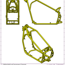
I’m currently building a motorcycle chassis. There are some tricky things that go into making this.
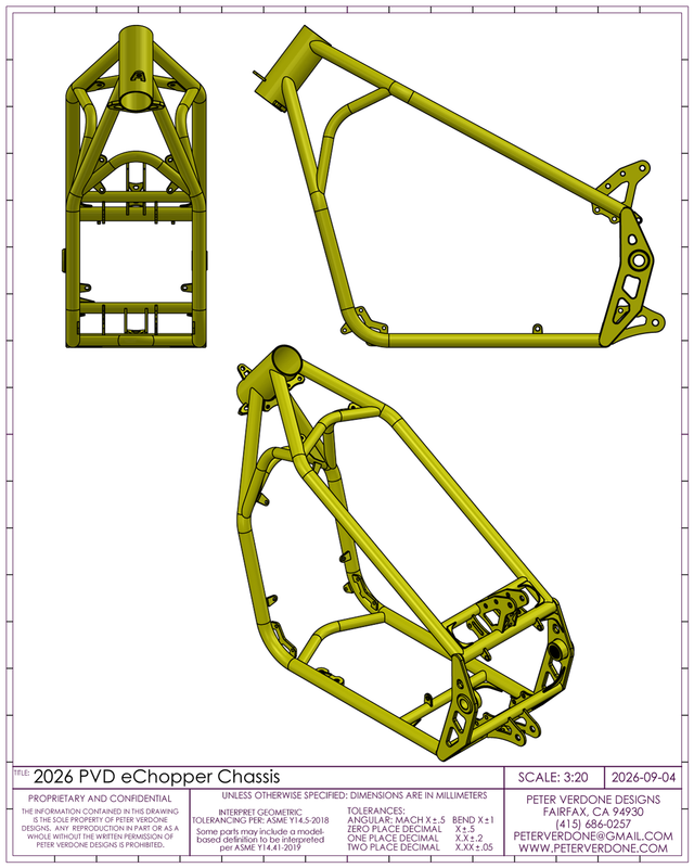
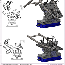
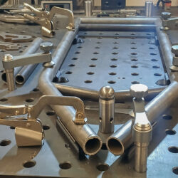
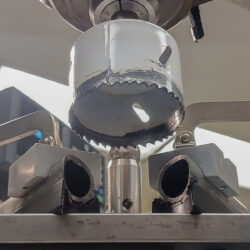
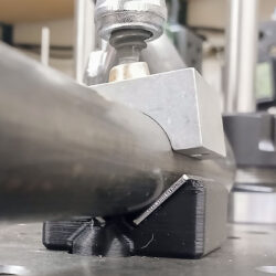
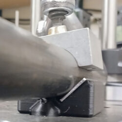
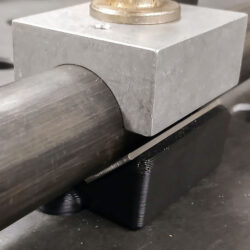
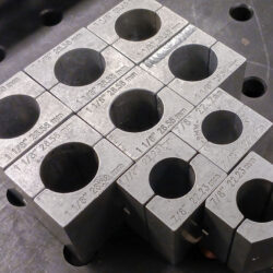
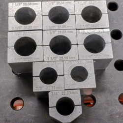
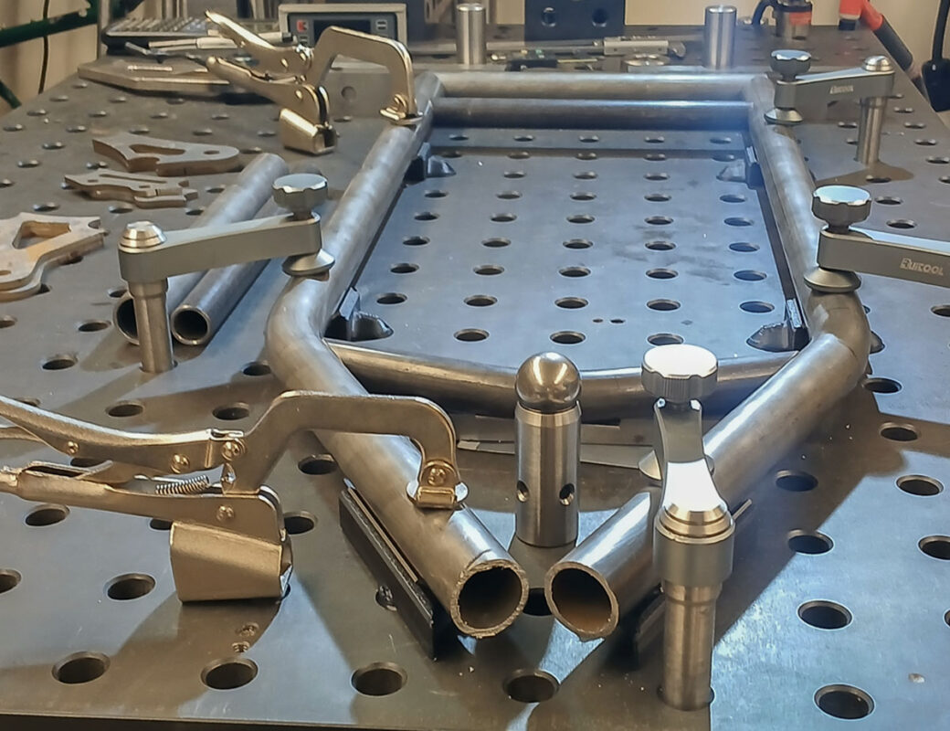
I try to adopt these new methods whenever practical, such as in the motorcycle tube miter/weld fixture below. It uses fixture table systems and FDM/PLA blocks to hold the tubes in place.
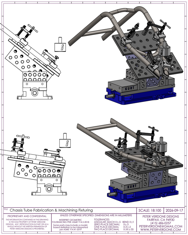
Fixture table systems and FDM (Fused Deposition Modeling) PLA tooling are amazing force multipliers in a small shop. Deploying both together in a fabrication setup is even more powerful, enabling complex work holding on a predictable, repeatable platform. However, this raises an important question: how do plastic components hold up regarding precision, rigidity, and strength under load?
We can do most of our planning easily in a modeling environment. Extremely complex alignment blocks can be 3D-printed to lock directly into a table raster board, making the machining and fixturing of complex weldments far simpler and more precise.
I’ve used FDM tooling in the past to hold tubes in unconventional configurations. Most notably, to cut handlebar struts that would otherwise be challenging machine. While that project was successful, my understanding of the underlying engineering principles when using these tools has developed significantly since then.
While the blocks used to produce those handlebars worked, there was an issue that experienced engineers would recognize, the tool incorrectly constrained the parts. The term of art is kinematic constraints. Specifically, how the 6 Degrees of Freedom (DoF) are controlled. Using a cylindrical bore to align a cylindrical tube does not provide precise repeatability, we use vee blocks and stops for that. Other problems in the design created ambiguous mates that were either under-constrained, over-constrained, or redundant.
Note that in the world of cycle frame fabrication, we use cylindrical tube blocks all the time, which appears to conflict with proper constraining. The reason is that thin-wall tubing (0.90mm wall) needs to be well supported during machining so that it doesn’t distort or get ruined under clamping loads.
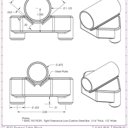
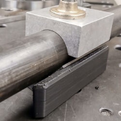
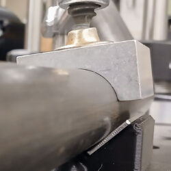
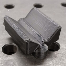
For my current project, I am using FDM V-blocks combined with fixture table components. A precision 100-degree V-block provides two discrete line contacts. Because I am using much thicker, more robust tubing this time, proper kinematic holding is easier with risking tube damage or error.
However, FDM prints lack precision and have much lower load-bearing capacity than metal, making them susceptible to deformation under shop loads. Addressing these limitations is essential if I plan on using them in my tooling.
The first step in this process is calibrating the filament profiles and CAM settings in the slicer. We need repeatable and predictable results from the printer. The physical part must match the CAD model. Thus, filament extrusion properties need to be set and the size of the part must be calibrated.
In my shop, I use an AnyCubic Kobra S1 FDM extruder with OrcaSlicer 2.4.2. Most of our general printing uses AnyCubic PLA 3D Printer Filament (1.75mm, Black, #212721) which is what I am using here. While other materials offer superior mechanical properties for this application, my goal is a design that works reliably using basic, widely available materials.
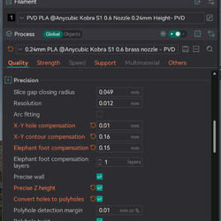
A full filament calibration should be performed in the specific machine being used, checking carefully for material shrinkage. Then, X-Y hole and X-Y contour compensation (under the Quality: Precision tab) should be adjusted. With proper measurement tools, we can get the print extremely close to the target dimentions.
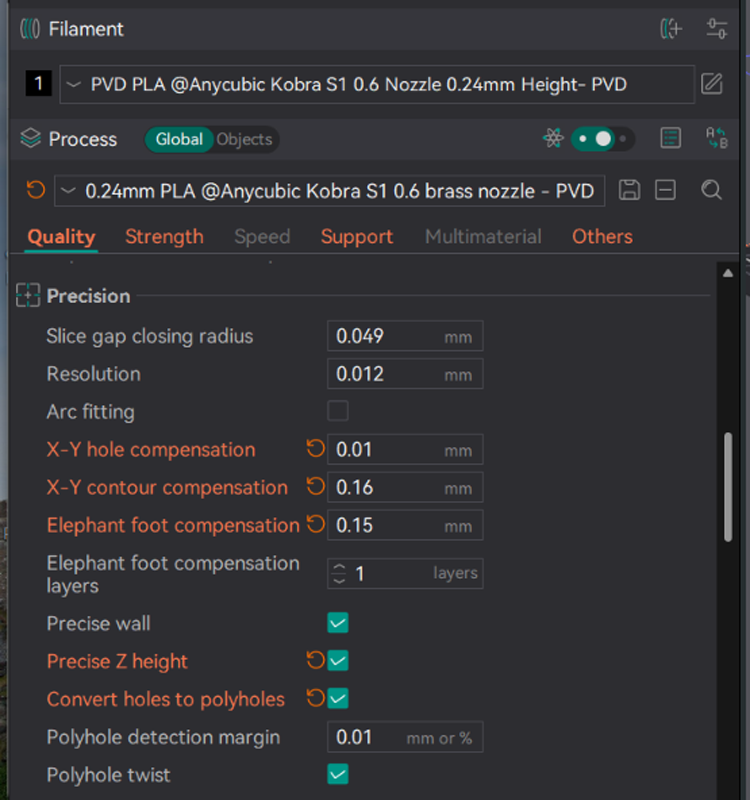
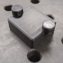
I modeled a calibration block tailored to these specific requirements. Using precision shop tools, I measured the the outside dimensions, bore diameter, and pin to pin center distance which is critical for mating with the BuildPro 5/8″, 2.000″ x Ø 0.625″ table raster.
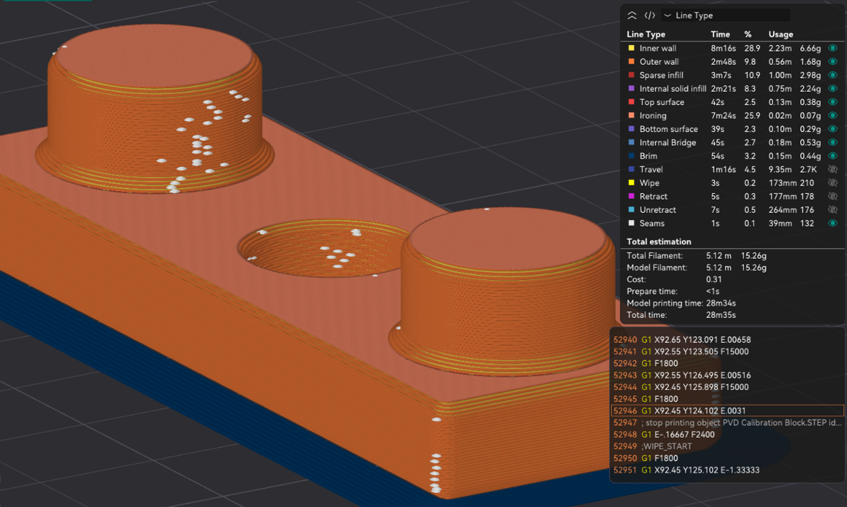
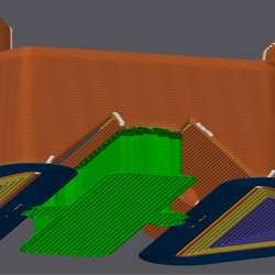
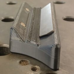
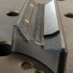
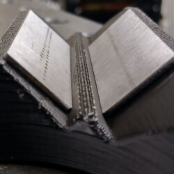
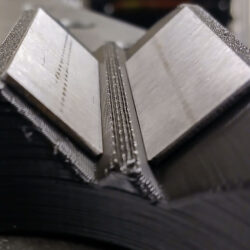
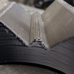
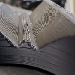
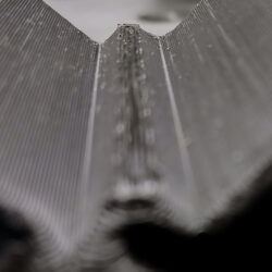
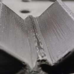
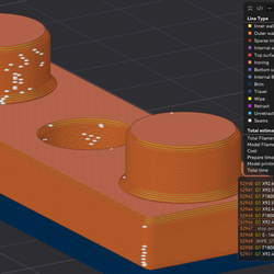
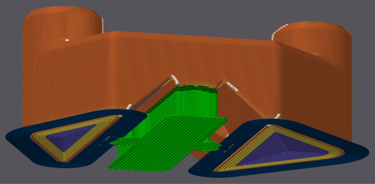
Once the printer settings were calibrated I designed the geometry of the tooling block. The block is oriented to print with the locating pins facing upward. This yields optimal surface finish on critical mating features and aligns layer lines for maximum strength against anisotropic weaknesses. Notice that only certain functional features require high precisions; non-critical areas can retain minor support artifacts without affecting performance.
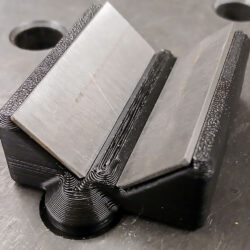
I parameterized the CAD model so the V-block angle can be adjusted with a single dimension update. I’m using a 100 degree angle as it will be more compact than a 90 degree angle and direct forces down toward the table rather than outward. I had tried 105 degree but felt a bit more lateral support could be had. The thing that this compactness adds is much quicker print times!
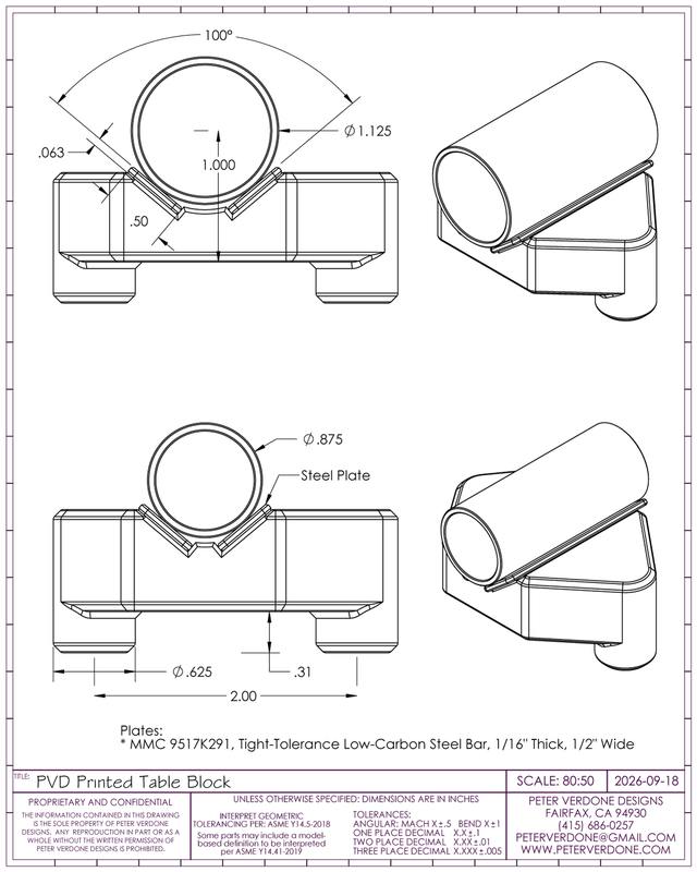
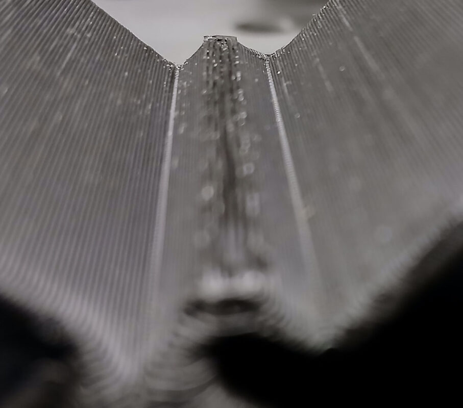
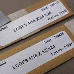
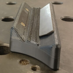
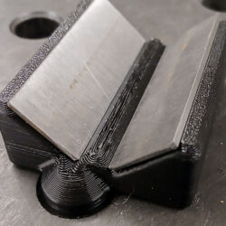
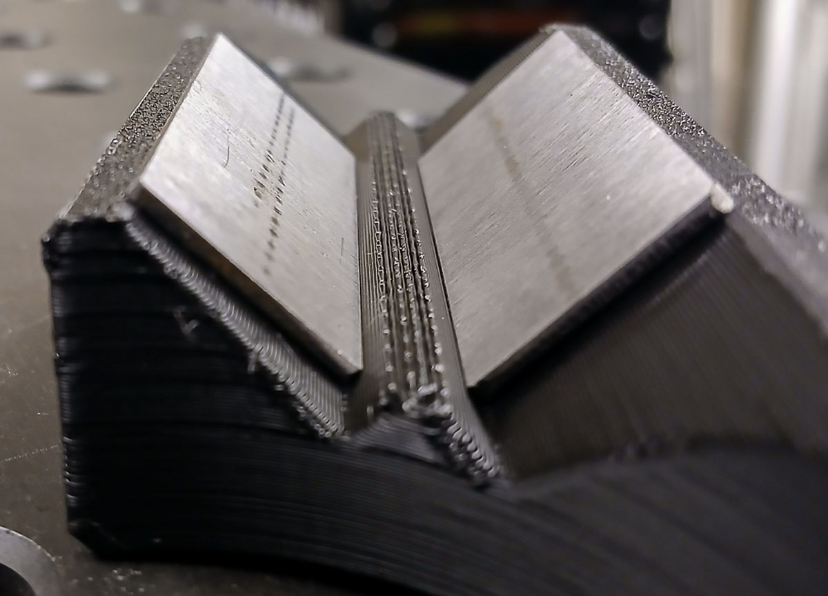
What makes this design work so well, is the integrated LCGFS (Low Carbon Ground Flat Stock) flat steel plate interface. This is crucial. By adding a thin steel strip to the V-groove, many of the problems with PLA prints are mitigated.
- Load Distribution: The line-contact pressure from the tube is distributed across the broader surface of the steel plate rather than crushing the thin plastic edge.
- Accuracy: The tiny deviations from the theoretical surface are averaged to help the reference be accurate.
- Rigidity & Creep Resistance: PLA has a flexural modulus of roughly 3.3 GPa versus mild steel at 200 GPa (about 1/60th the stiffness). Adding steel prevents localized point -loading, plastic deformation, material creep under sustained clamping loads.
- Thermal Resistance: The steel can handle heat better than the plastic and may provide some some stability when the tube is warmed.
- Wear Resistance: The mating surface is as hard as the tube is for increased repeatability.
- Best of all, adding this plate to the printed block is as easy as cutting a length from the strip and deburring it.
My friend, Ronen, suggested that I add a pocket on the faces to glue a small magnet in the printed block. That’s a great idea and was proven quickly when testing blocks without magnets. It was a PITA ensuring the plates were always in place. Magnets were added to the newer parts and I consider them necessary to avoid a huge fuss keeping plates in place.
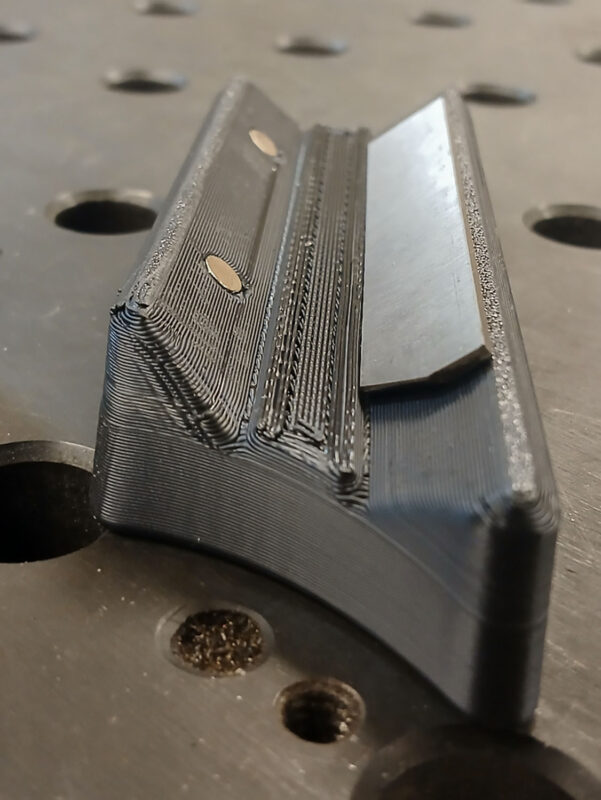
He also agreed with me that stainless steel would be nicer as it wouldn’t rust but the additional cost of that material makes no sense right now. It would also be an issue using the magnets.
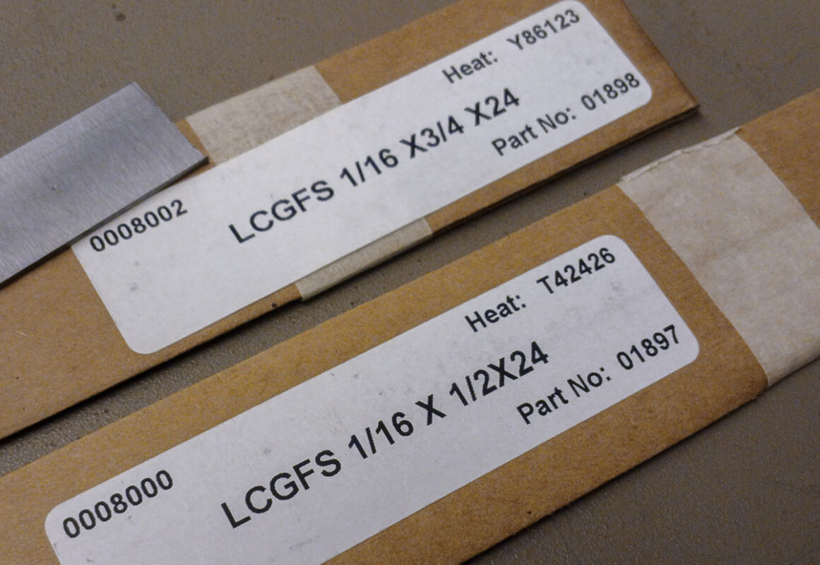
Initially, I was looking at 3/4″ and 1/2″ strip steel for the plates. As I’ve fine tuned the design, I’m looking at 1/2″ and under. More compact and easy to cut quick. I’m going to add some 3/8″ steel strip to my next McMaster order for other situations.
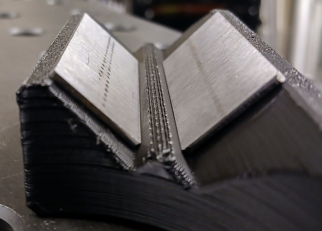
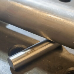
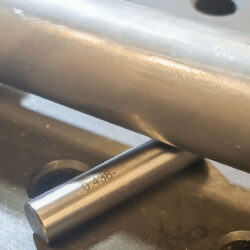
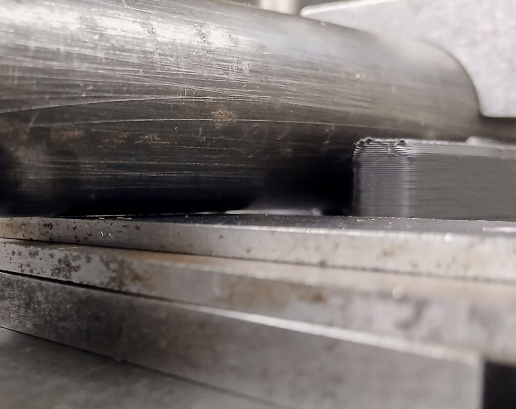
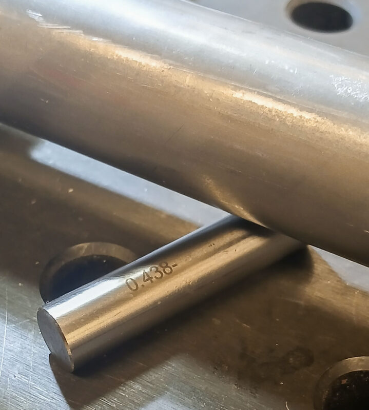
I can check the height over the surface using various gauging components. The block shown has a 1/2″ gap over the table. Showing that with a 1/4″ and two 1/8″ block confirms that on either side. Perfect? No. Perfectly fine? Yes.
The next level that this can be taken to is getting Multi Jet Fusion parts produced from Nylon 12. This would be a real increase in both strength and precision. This is becoming very inexpensive and quick to have done by US suppliers. After that, DMLS parts of 316L from China.
Now that this detail is sorted and part of my method, I can move forward with the rest of the fabrication of the chassis. I feel that this sidebar was well worth slowing me down as so much more is understood for making nice tools.