The job of the handlebars, stem, and spacers on a bicycle is to place the hand grips above (or below) the headset and with the grips in the correct location for the rider’s body, style of riding, and goals.
It’s a relatively simple task that is often screwed up by the user or technician. This is a crucial concept in custom bicycle design because when we understand the finer details of this, we can exact far more performance out of a bike than if we used coarse approximations as are found on a poorly chosen production frame.
For many, lack of understanding of this results in the purchase or construction of the wrong size bike.
I’ve done a lot of work in the past few years with the design of the bicycle chassis, all the way to where it meets the hands. In the last eight months developments have been revolutionary. That is, once we decouple the hand grips from the front wheel (traditionally coupled) the ‘no fly zone’ becomes an option for improved setups of fit and handling. This big change started with the Warbird bars and continues through all of my subsequent designs.
While this is all great news for advanced bicycle design on my own bikes, many novice builders and consumers are relegated to commercially available parts. It really does make sense for these riders and builders to use parts that can be easily interchanged, as nailing a fit right out of the computer is extremely challenging and if a design doesn’t require full integration, it’s not a very good idea to do.
My Blackbird MTB chassis (2017) was designed using commercially available parts and is still well ahead of what you find others getting from their designs today. I see this as the outer limit of what can be done without custom work at the bar and stem. This, of course, for my fit and goals at the time. New designs, and age, have influenced what I do now.
This post covers parts that others are working with. Parts that are in the marketplace and how the concepts for working with these stems, bars, and spacers influence design.
First, we place the grips in position. Through testing, we arrive at a set of coordinates from the bottom bracket. This will often be the most forward and low position allowable, given upper body and core strength, and ergonomics of riding style. We can use the end of the handlebar to approximate the hand placement. Note that as sweep angles increase, this approximation becomes a little less useful but is still closer than other methods. The final coordinate is an offset from the bottom bracket.
I use a 65° head angle of the chassis in these models, as it is common in mountain bike design in this era and shows the concepts at hand. Different bikes will use different angles according to the design goal. I’m not trying to show every case.
I tend to model the rotation of the bars near a 20° sweep angle of the bars from horizon as this closely reflects how I set up my bikes. This is a preference, but the proper set-up for any rider would only deviate ±5°. If your bars are outside of this range, you should investigate your testing process.
Accurate and descriptive models of the handlebars and stems are essential to doing progressive work. The problem here is that the bicycle industry, who largely doesn’t understand these parts, is not describing them properly in their technical literature.
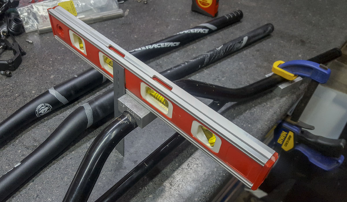
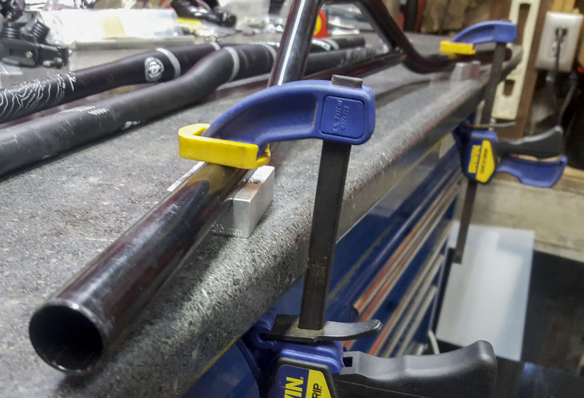
For handlebars; what on earth is upsweep? It’s not a thing. Seriously! Are the rise numbers reported based on the wrong perspective? Almost always. I draw bike parts all the time and I still don’t understand what the marketing people are describing. Certainly, I need different numbers than they provide. I always take physical measurements of handlebars if I’m going to use them. I want to know the width, the sweep, the real rise, the grip length, and a few other geometric factors. This could be resolved to a coordinate of the end of the bar from clamp and sweep. We don’t ever see that.
Below is a selection of handlebars I had laying around that are drawn more descriptively: (geometrically accurate, not in appearance)
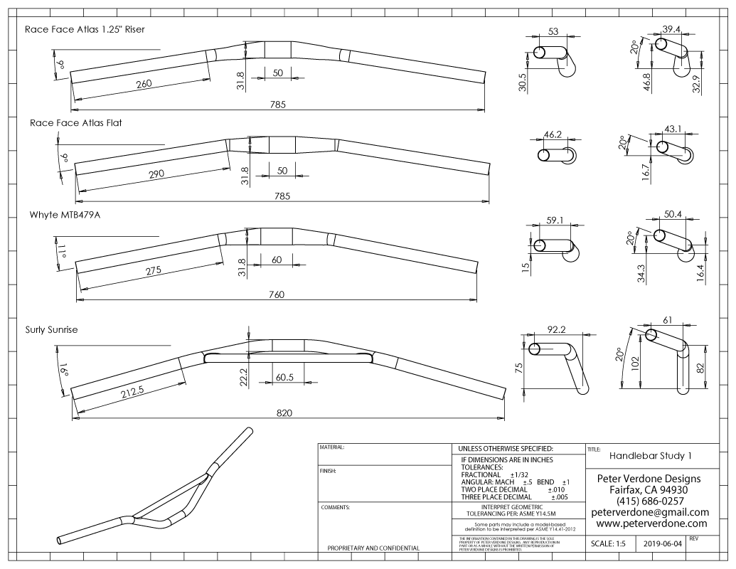

Looking at these bars, it’s clear that the changes in rise, width, and sweep angle produce hand grip positions very different from one another. Often, the difference can be over 20mm on what would otherwise be assumed to be a similar handlebar. That’s the difference of a frame size. Also, as the bars gain width, the reach to them will need to shorten some, it may be good to do this with increased sweep.
Stems cannot be described using their ‘length’ and ‘angle’ as these values truly don’t exist. They might reflect something about the stem but nothing that the end user cares about. What we need are the offsets from the center of the base to know what shape a stem takes. One company’s 90mm x 15° stem will be very different from another’s version.
In my models, I use a generic model of a stem, roughly based on a Salsa Guide stem, as it comes in such a wide range of sizes. The stem in front of you may be a bit different.
Like I do with the handlebars, here I’m showing the stems as described and in position.
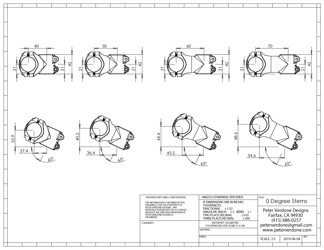
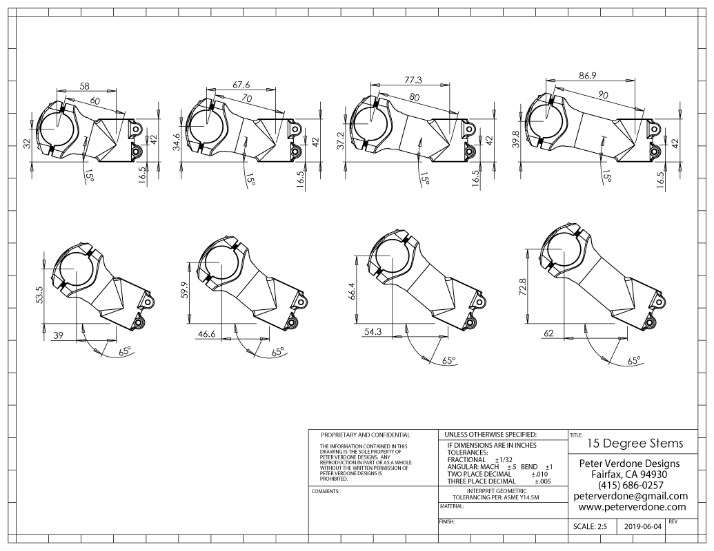
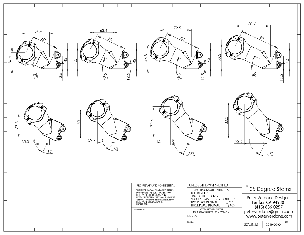
For most modern bicycle designs (outside of track, criterium, and some other pure racing bikes) we are going to use the shortest stem possible on a custom frame. While 31mm stems do exist, it is a mistake to design for that length. It is better to base a design around a 40-45mm stem so that a 31mm or 50mm stem can be used for different types of rides or if the planned fit is slightly off the actual build or bar choice.
Below is a drawing showing a 40mm x 0° stem holding a Race Face Atlas 1.25″ Riser handlebar and a Race Face Atlas Flat handlebar. A spacer was added in a few configurations to place the end of the bar in similar positions from the center of the top of the headset.
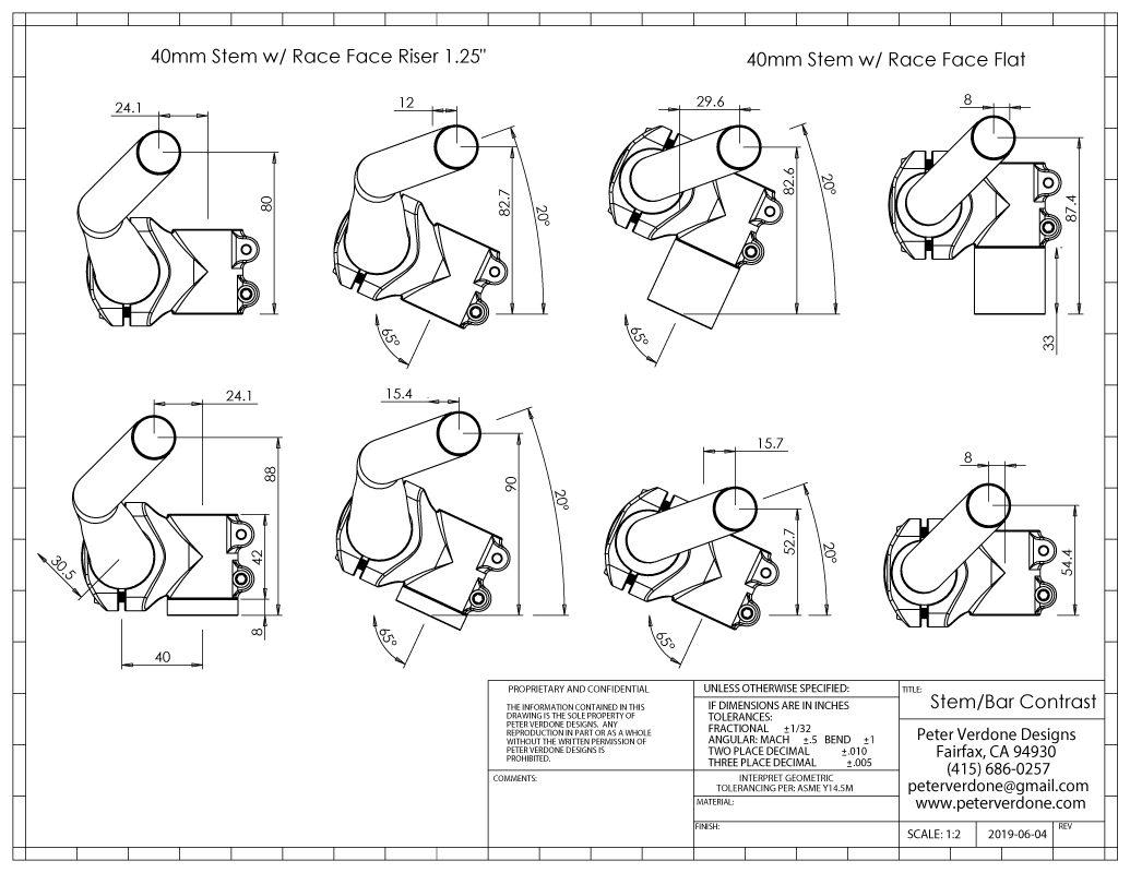
These are identical handlebars in their width and sweep but the rise of the bar combined with the roll from horizon produce a very different position. Notice that the flat bar with a 32mm spacer sits at the same height of the riser bar setup but 17.6mm closer (horizontally) to the bottom bracket. The riser bar with an 8mm spacer sits in about the same horizontal position from the bottom bracket but is 37.3mm higher. These are major changes with real consequences in the design of a bike.
This is where understanding headset spacers comes in. Adding a spacer moves the grips higher up (Spacer * sin(HA)) but also farther back (spacer * cos(HA). With careful choices, stems can be swapped for spacers with identical results.
Certainly, if I had just had a custom bicycle designed and constructed for me, if I wasn’t able to use my chosen parts or if parts didn’t exist that produced the fit that I wanted, I’d be pissed as this is exactly the job description of the custom builder. Sadly, few go to these lengths.
Worse, I see terrible bicycles that are “custom” produced that are far too short for the riders, as displayed by stem lengths well over 50mm and very upright riding positions. These bikes aren’t built to be best for the riders. They are easy for the producers of them to churn out and get done.
Here’s what the BikeCAD file should look like if you are looking at this part of the bike correctly: (not from an actual bike)
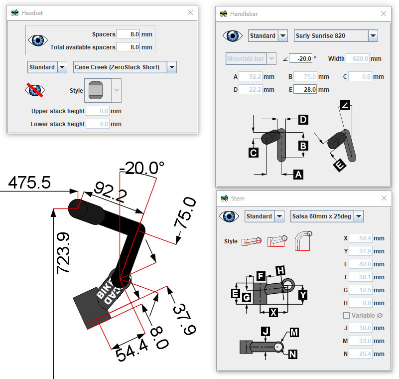
Hopefully, BikeCAD can be improved on how handlebar data is entered to make the model both accurate dimentionally but also reflect the real shape of the bar. It may look goofy but a dimentionally accurate model is what we have to have. Pretty pictures help with sales.
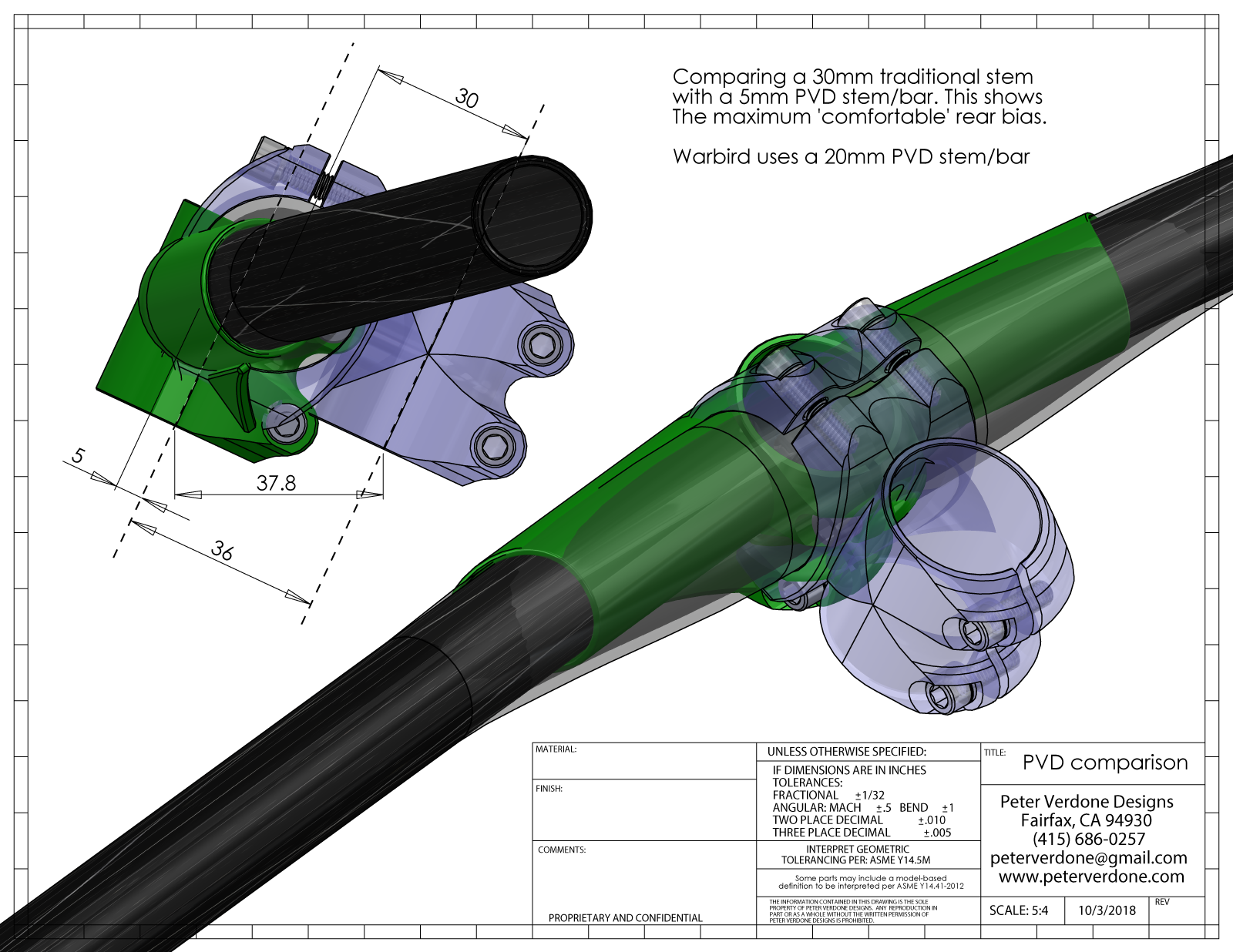
It’s these issues, exactly, that led to my development of a new type of system that allows for more choice in position of the grips relative to the front wheel and allowing for full vertical adjustment. The drawback, currently, is that these have to be custom fabricated. This may change if the parts guys are pushed for this kind of product. On the plus side is that I end up with a faster, funner bike both up and down the hills.
This topic will always be incomplete as it always comes down to individual designs and goals. My goal here is to inform fitters, designers and constructors of an very important and almost always overlooked detail. If the goal is “the best” bike for a given rider then a design must go into this level of detail.