Dummy axles and how they are held are a crucial part of a frame building program. We have to accurately place where the wheel axles will be, just as we do with the various tubes. The frame should hold the hubs so that the tires, gears, derailleur, and rotor are in plane, centered among the critical axes. This requires precise locating of the dropouts.
I had two issues that needed to be rectified in the recent build of Windy’s Vega frame.
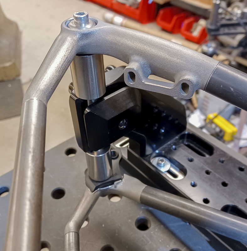
- The dummy axle holding arm for my Cyberdyne fixture needed a modification. The design and production of the fixture was an expansive project done at the start of the COVID times. While many details were done very well, some not so well. That is the game. The interface that held the dummy axle was sketched as a semi-circle profile to match the ⌀0.500″ x 2.500″ shaft section of the Anvil-style dummy axles. This has been customary in frame fixtures and can be seen everywhere. This was incorrectly kinematically constrained. Thus, some variance could happen in the positioning of the dummy. Trigonometrically, this error is projected and magnified to the tire area causing real problems for tube clearance and wheel placement as a tenth of a millimeter at the origin could become a full millimeter or more at the end.
- In moving to the SRAM UDH dropout system to allow coax derailleurs, an improved interface was needed for the tool to hold the dropout accurately. Common PMW dummy axles are simply Anvil dummy axle designs that were passed along when Don retired. They are generally based on now antiquated quick release dropouts. Thru axles and UDH have much greater requirements, and thru axles have a need for more precision.
Kinematic constraints (UoA .pdf) are an important concept in the design of precision instruments and fixtures. An under-constrained or an over-constrained fixture is a big problem. We can get instability or binding, which causes a loss of precision and repeatability.
As a long-time machinist and fabricator, I’m generally looking for increased surface area on tooling to combat the high loads and shocks that are produced during machining and welding. We love rigidity! We also see lots of wear in production environments when grit is present and parts are changed out frequently. Moving from aluminum in the design to steel (or even hardened steel) can help fight this but those solutions become issues of their own (cost and process) for craft guys (less so for large industrial operations). This explains the semi-circular cut.
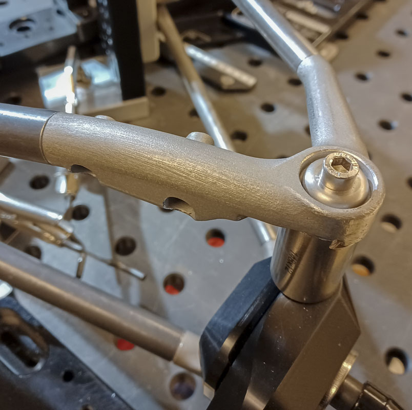
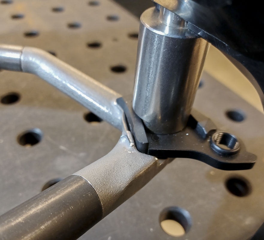
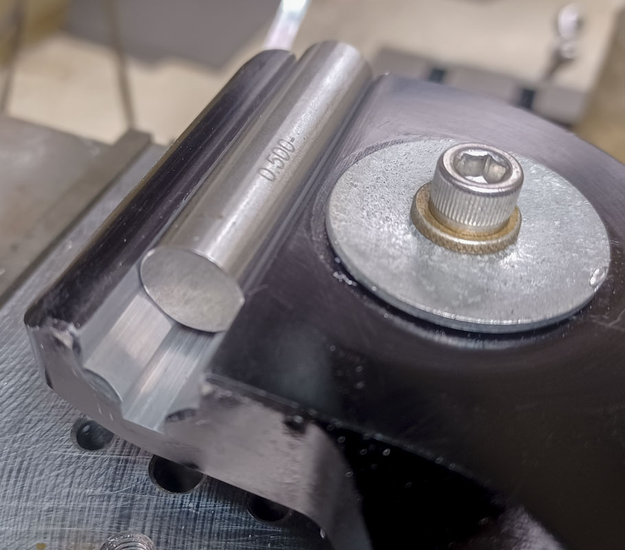
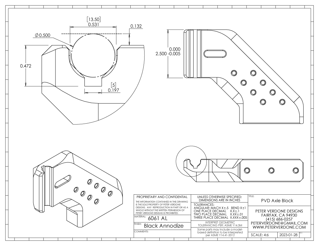
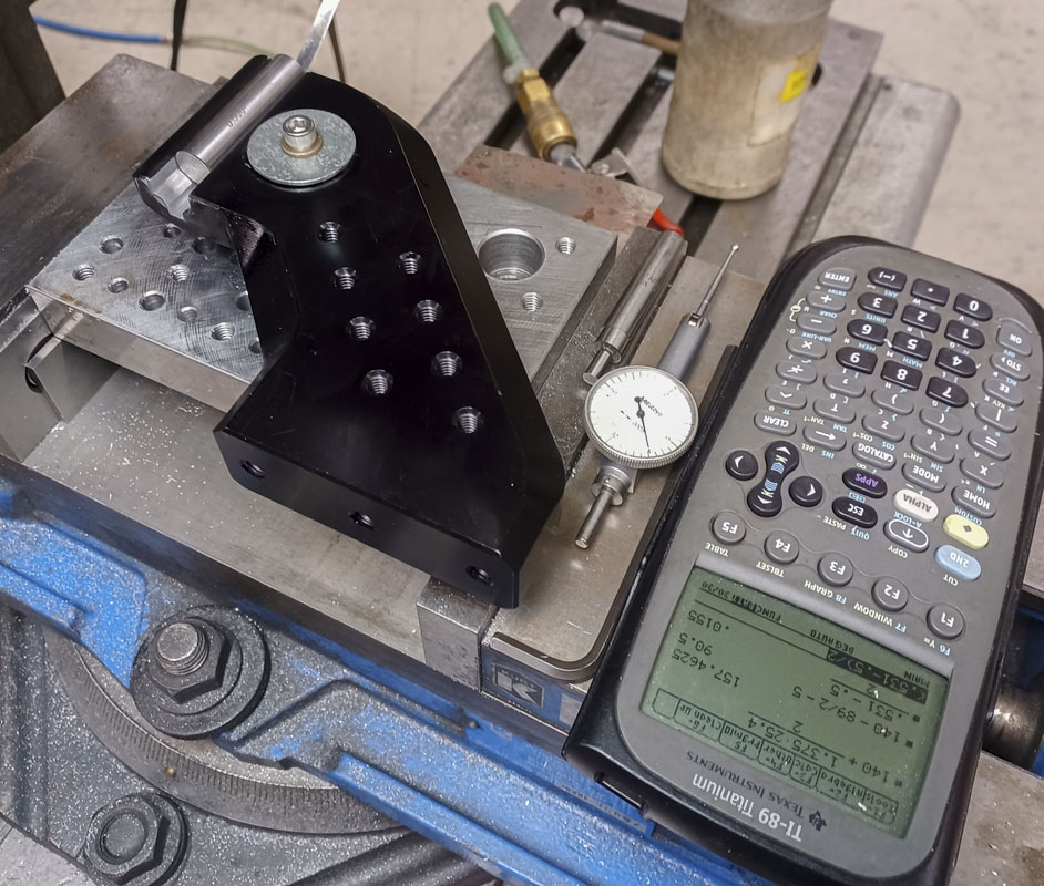
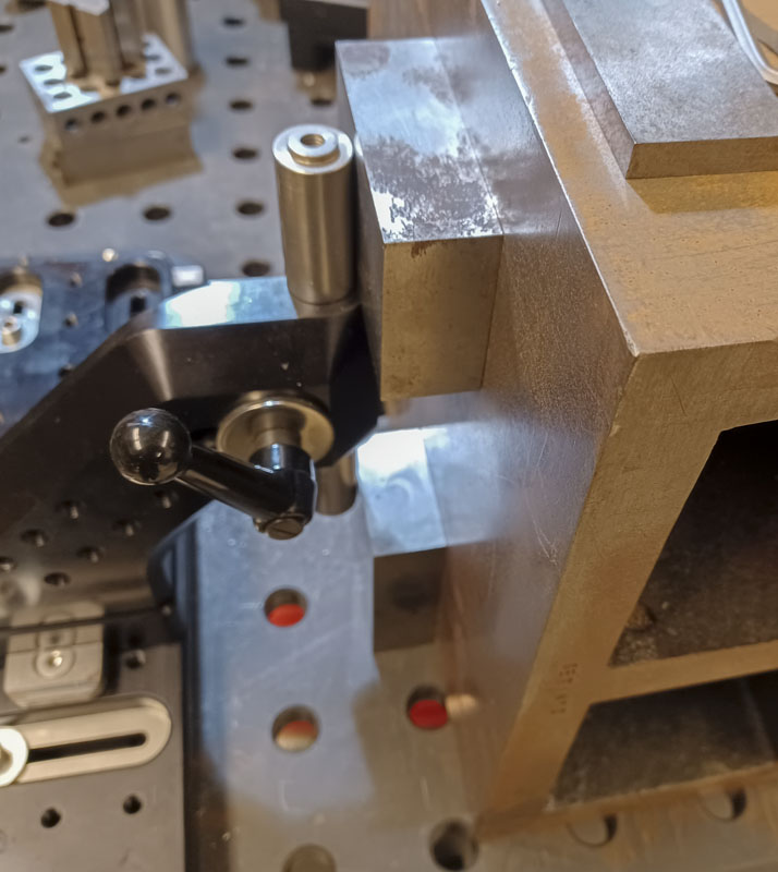
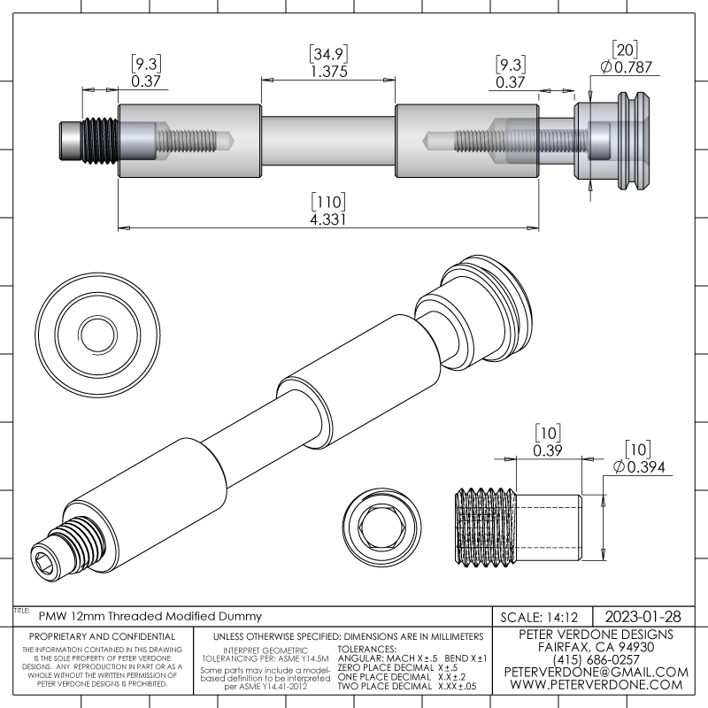
So, the axle tower needed to have a vee slot cut to replace the semi-circle. This will result in a just slightly under-constrained part though it will be 100% constrained axially. This was a tricky setup in the mill but the cut went fine and the fixture was blueprinted in post. The print for the modification is below. I’m updating the SKYNET and WOPR fixture to reflect this important change.

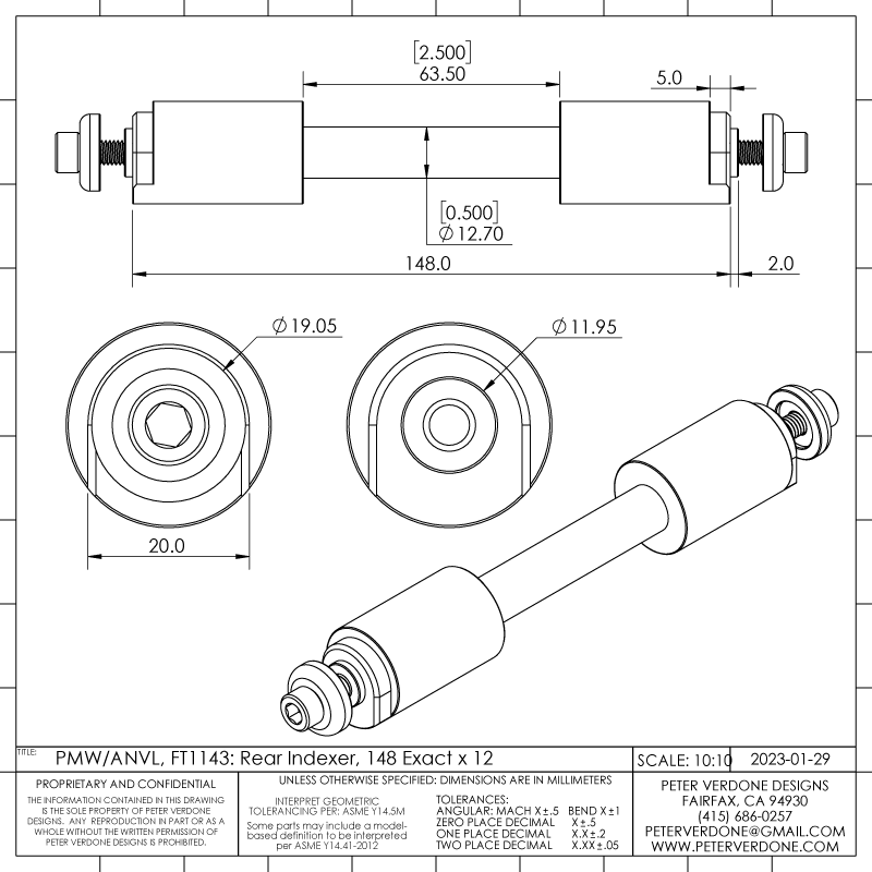
The dummy axle itself needed to be upgraded for use with thru axles and UDH. Below is a general print for a 148×12 indexing dummy axles as produced by Anvil and PMW. Notice that the dropout will be spaced quite well but in terms of concentricity, there’s a big problem here. The mere 2mm deep pin that is expected to locate the dropouts axially is often catching less that 0.5mm when 3D prints and filleted or chamfered bores come into the picture. This is even worse if there is a thread.
This may have been acceptable back when hubs were quick released and dropouts were slotted. Then, a few file strokes could bring a wheel into alignment. This leads to real problems now as any higher end bike now has thru axles. Today, we need truly positive location of the bores.
Decades ago, back when Don Ferris was early into making fixtures, he had a dummy axle for 150x12mm TA downhill bikes. Of course, I have one of these in my shop. Basically, it’s a custom shoulder screw threaded into the dummy using the bore and shaft to locate concentrically. It was a very nice design. A bit more expensive and flew well below radar of the framebuilders at the time.
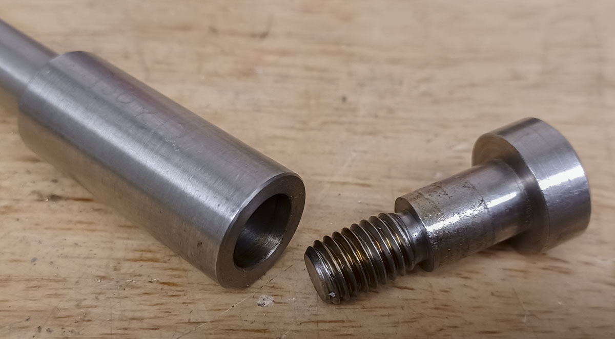
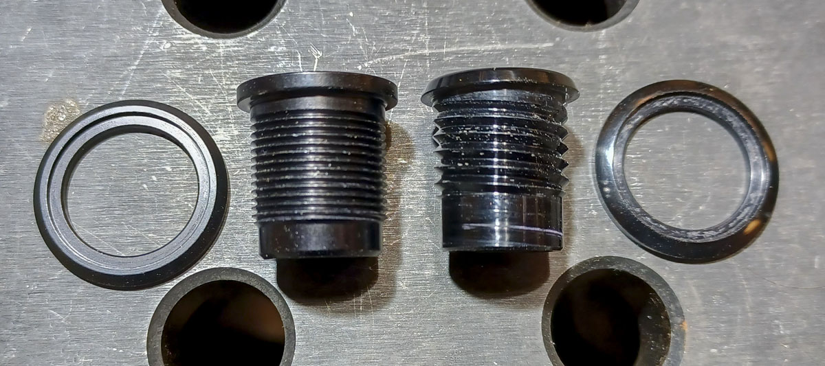
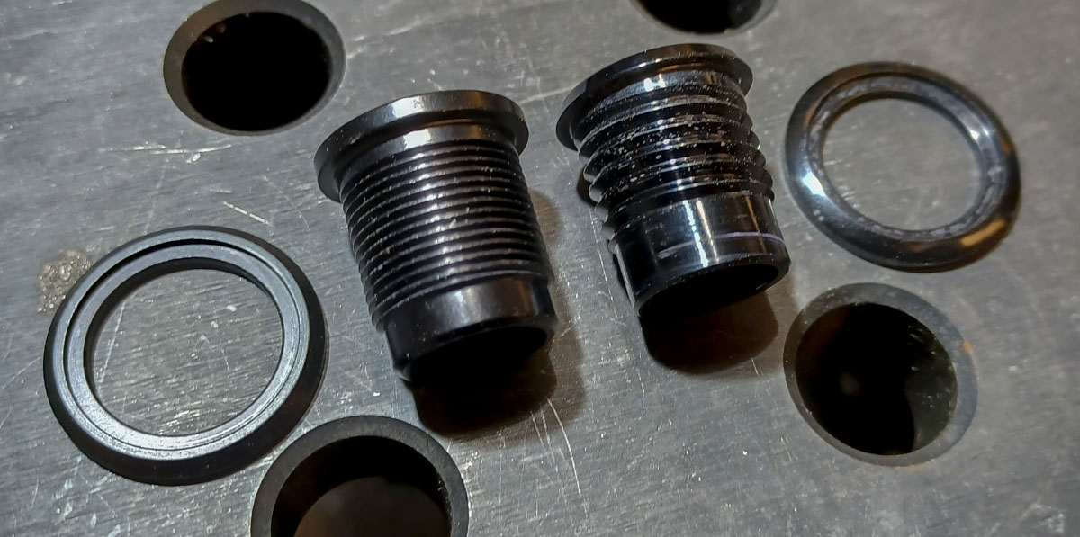
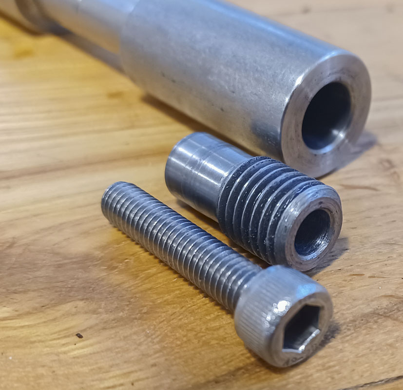
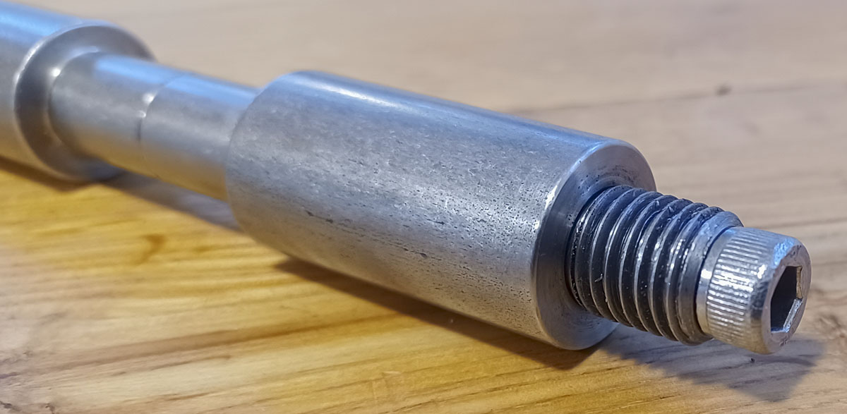
In 2018, when I was building the PVD Bird of Prey, I finally got to producing a solution for making forks with a M12x1.5 threaded side. How to hold these dropouts? Indicating on a partial section of thread was a non-starter. So I made a pin and plug with a steel threaded rod, cut down to a 10mm pin with a through bolt. The pin is threaded down into the dropout, it locates in the dummy bore, and then a screw holds the parts together. It was an elegant solution to a tricky problem. The only real problem with this is that it forces one side of the dummy axle to be bored to 10mm instead of a more universally convenient 12mm.
I had intended to upgrade all of my dummy axle inventory to work with through axles like this but, as usual, I got distracted by fresh problems. This turned out to be a good thing as in the current era, we’re looking at a slightly different scenario.
Now, I’m building with the UDH. There are a few locating problems using traditional dummy axles.
- The drive side is a 20mm bore while the non-drive side is a 12mm bore.
- The drive side is offset 7mm outboard to account for the UDH hanger.
- Attempting to use a UDH hanger in the system to locate the dropout provides marginal purchase on standard dummy axles and can be wildly under-constrained axially.
- Clocking!
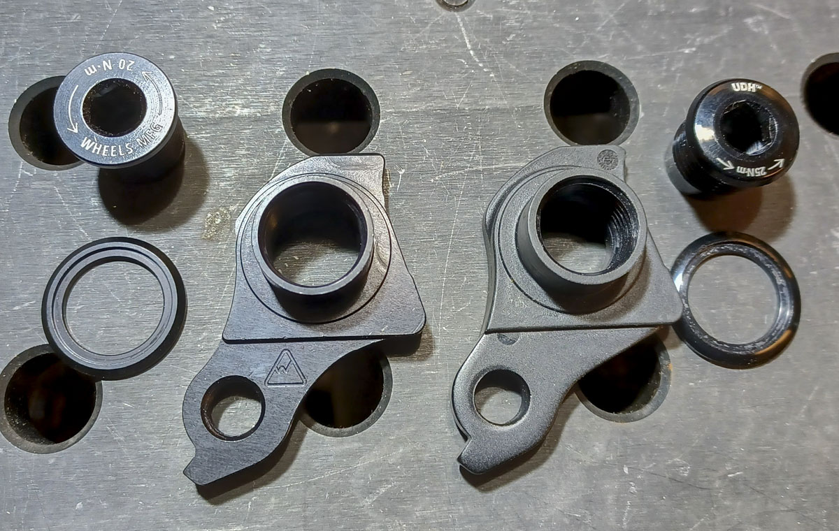
- The SRAM UDH hanger (AC-DRHG-MTB-A1) itself is plastic coated steel and not confidence-inspiring as a precision locating part.
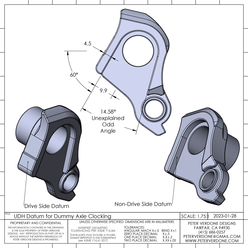
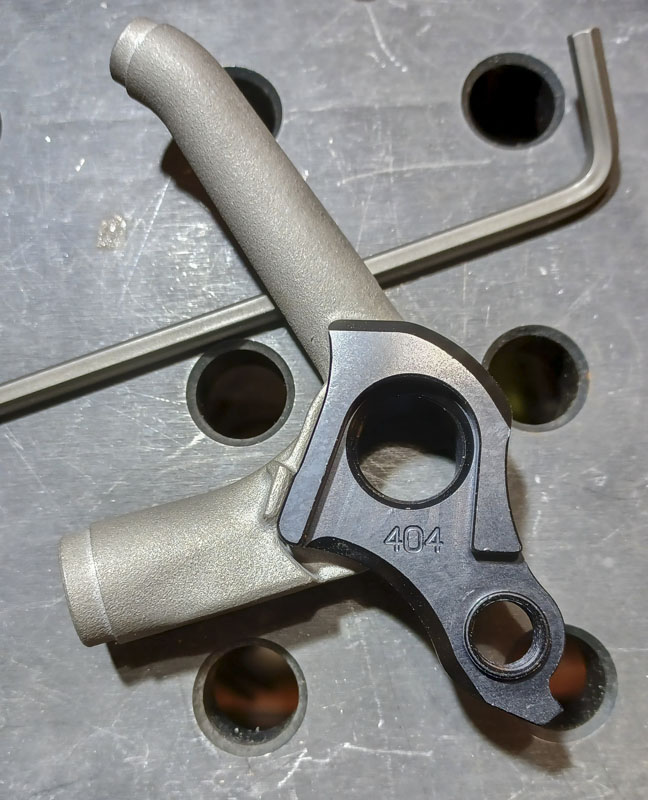
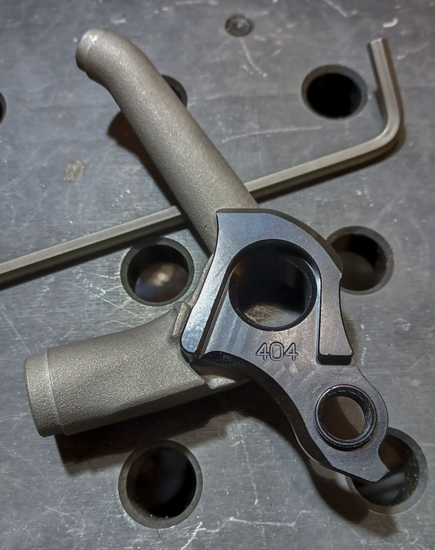
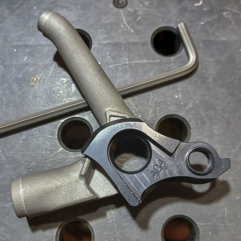
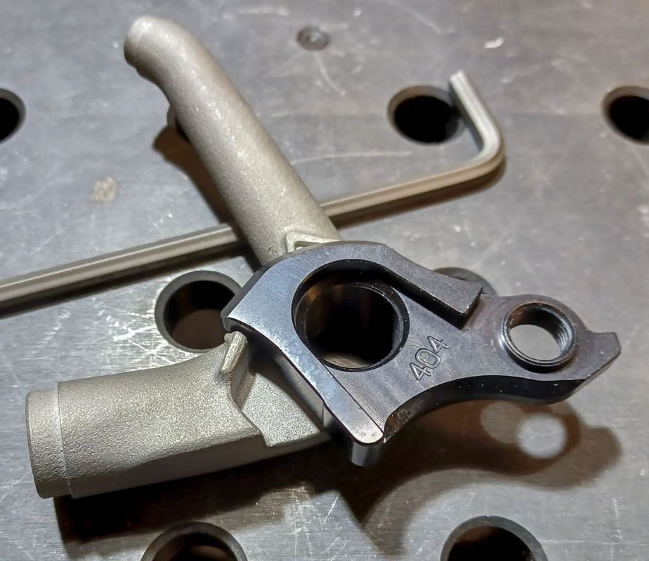
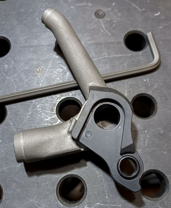
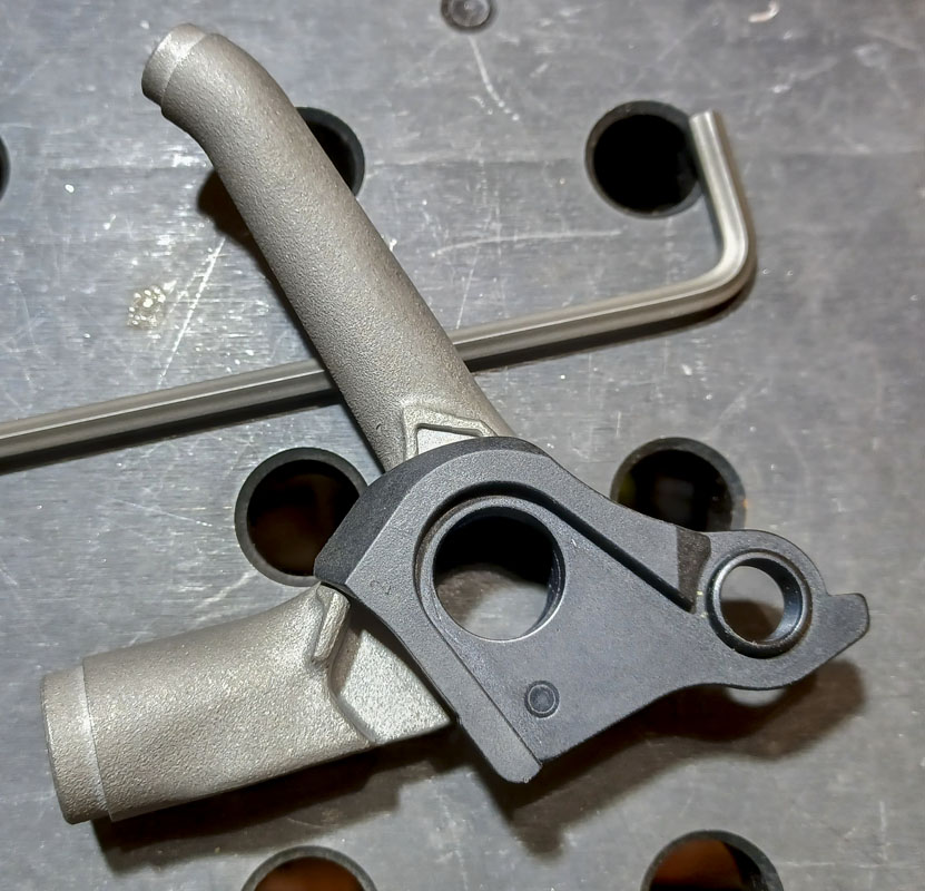
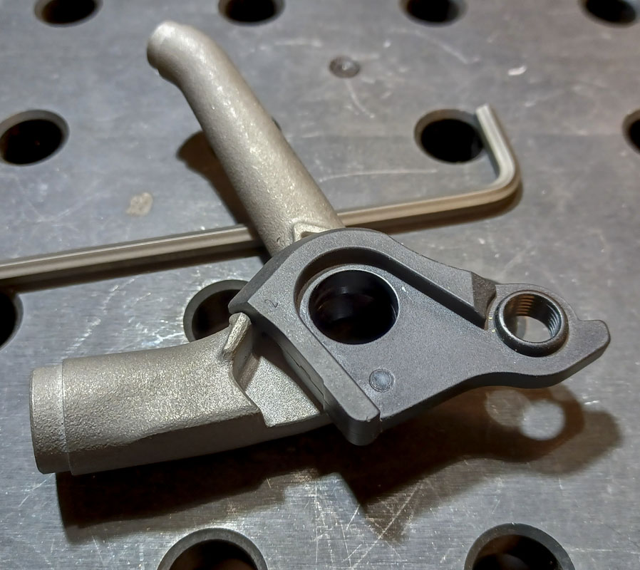
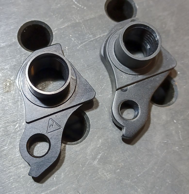
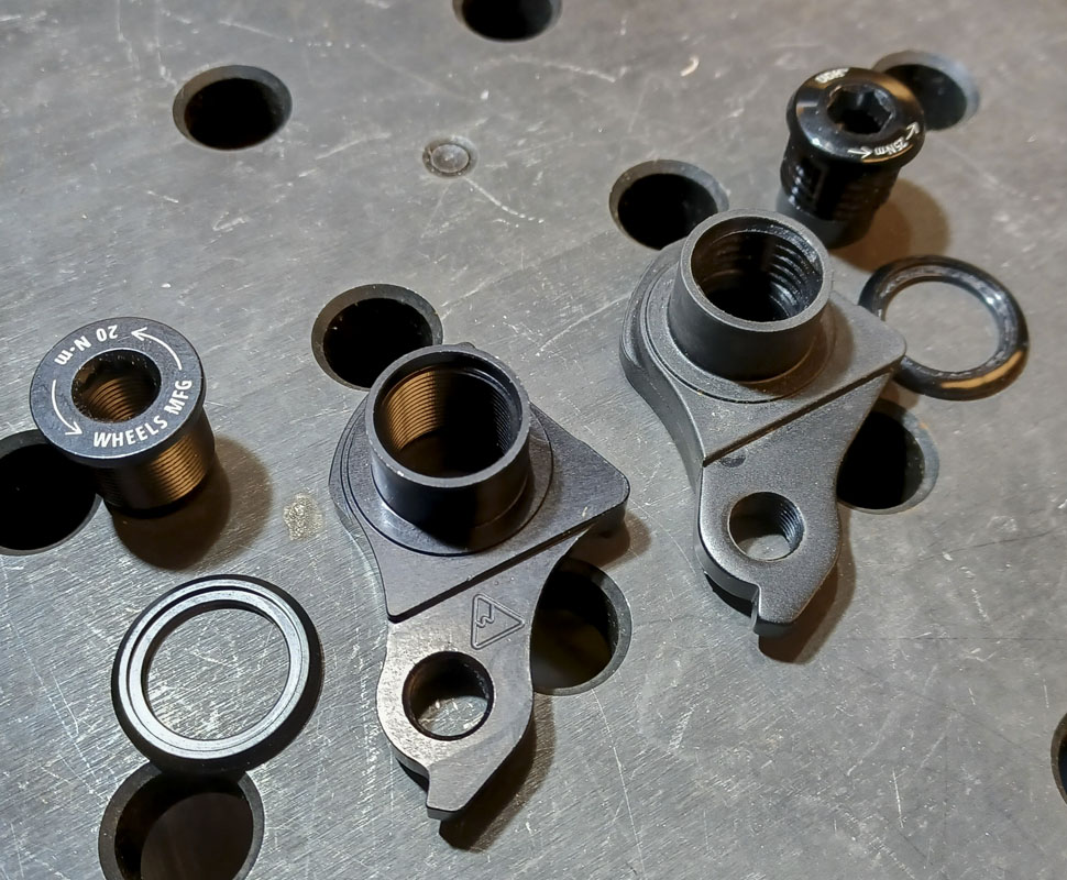
Addressing the last point first, Wheels Manufacturing has a machined full aluminum replacement (DROPOUT-404-UDH) for the OEM SRAM part. It’s a lot nicer for higher end builds and should have a more precise location…and won’t melt around welded parts. I have a few of those in hand but the axial location on the dummy tab was still vague as with the traditional dummy axles. This was not a big improvement in the setup.
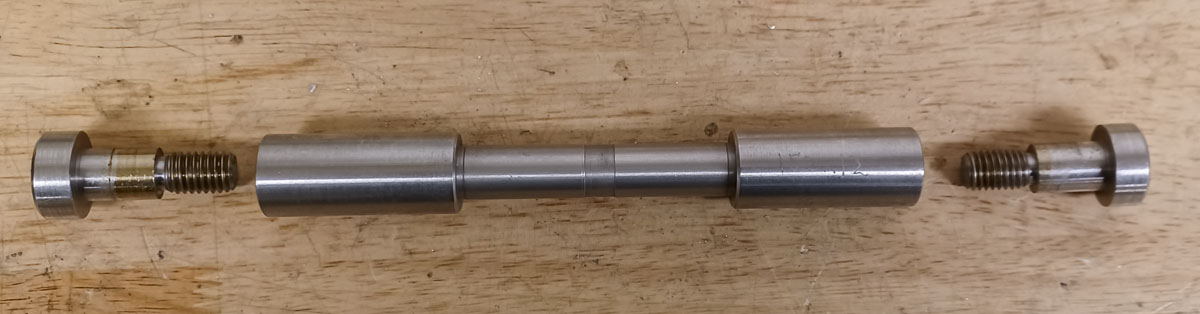
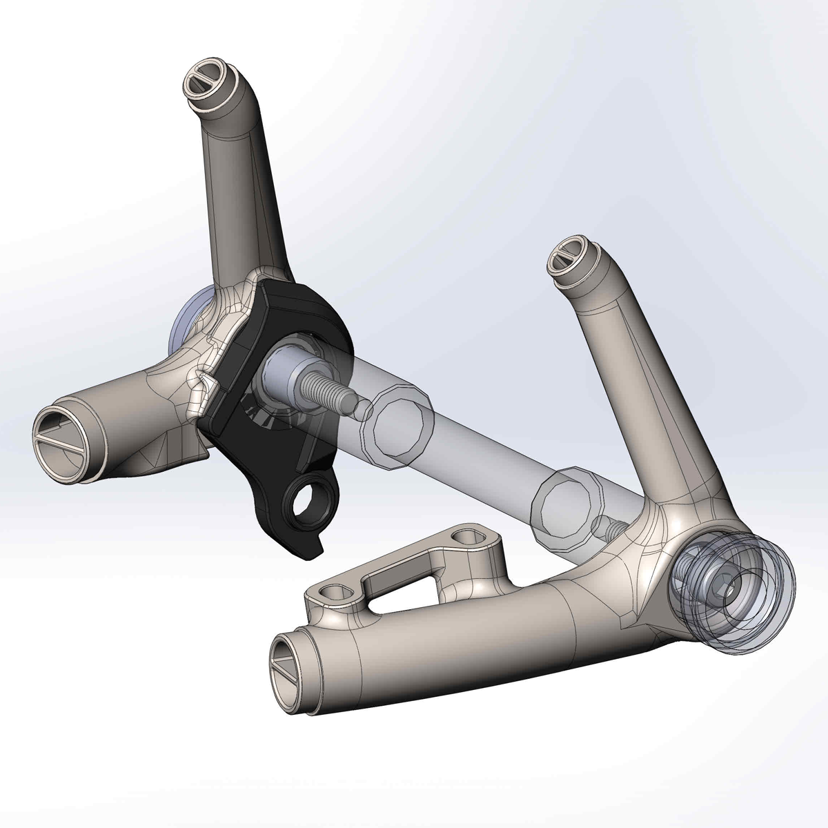
I was going to need to set up up my dummy axle differently to have real faith in setting up for UDH. I designed a modification to a standard dummy. This locates the parts precisely axially and clamps the parts fast, without using a hanger.
 Using the new dummy axle that I made for UDH is quite confidence inspiring. I have no worries about axial location anymore…except for clocking.
Clocking of the dropout is another issue entirely. On the Cyberdyne fixture, it’s relatively simple to reference the dropout sides from the table and set the clock. Most folks do not have this ability, as most use beam fixtures. I didn’t do a lot of work on this. I talked with Mark at Paragon some about it. Somebody will have to figure it out as I’m moving onto other problems now (ha!). It’s simple to understand but economically sound design and execution is going to be a bit of work.