When we work in engineering and design, we refer as much as possible to ‘first principles’, those datums or facts on which the entire project rests. “A basic assumption that cannot be deduced any further”. Everything comes back to these. They are both our lighthouse and safe harbor.
In bicycle design, there are many of these (driving parameters and job descriptions) that we can apply to the product. We want to place the wheels correctly from the rider, the grips, saddle, and the cranks at just the right relationship, etc. Will it be a rough off-road bike or a road racing bike or something else. This is for another post but you get the point.
There also exist what I’m going to call ‘second principles’. These are the very important things that we need to understand from those first principles. They tell us more about the shape things will be taking and may even cause us to re-evaluate the driving parameters and change them. We refer to many of these in common discussions. What is the front wheel trail? What is the flop? Some are more important than others depending on if we are riding the bike, assembling the bike, or building the frame from scratch. Context changes the value of the values.
In this post, I’m discussing just four of them (there are plenty more). They provide important shortcuts at the start of a build, in setting the fixture or laying out a table, or modifying a setup.
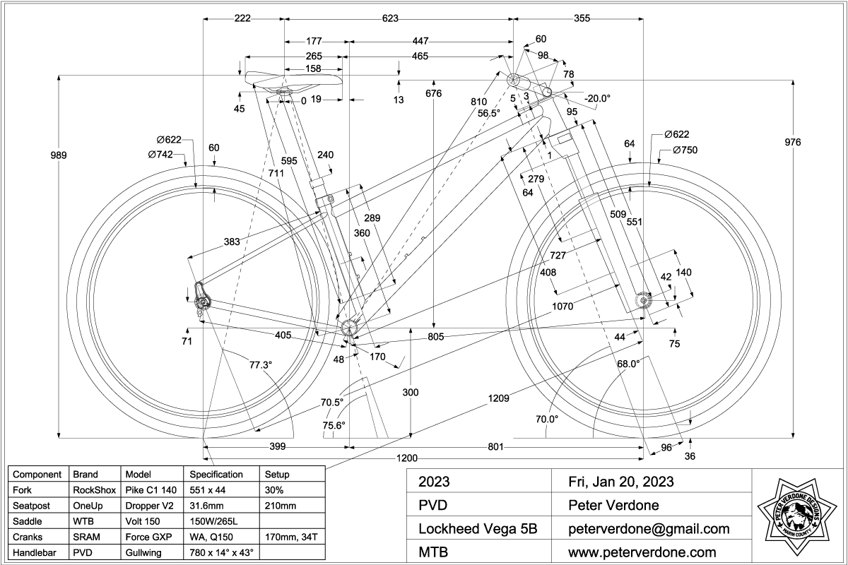
Let’s reference the #instagram print of the mountain bike that I’m currently building for my wife. Many of the driving parameters are expressed here but I am limited in what can be shown without making a total mess and fitting into the 1×1 space readably.
![]()
(I’m honestly having a problem with the direct measure of front and rear center being used as driving parameters instead of the horizontal measures. Arguments exist on both sides and I wish I could discuss this with someone that understood the dilemma.)
The secondary dimensions I’m discussing are:
- CaBar – The distance from the crank axis from and normal to the head tube axis. (727mm)
- CaBarOffset – The distance from the bottom of the head tube to the CaBar intersection along the head tube axis. (279mm)
- RaBar – The distance from the rear axle from and normal to the head tube axis. (1070mm)
- RaBarOffset – The distance from the bottom of the head tube to the RaBar intersection along the head tube axis. (64mm)
These are four key values for someone who is going to build a bike hardtail frame or model it in a kinematic system. They should not be ignored or be oblivious of. In essence, they define where the crank axis and rear axle (on hardtails) are placed in the rigid structure relative to the bottom of the head tube and the head axis.
This does fall apart some when working with a rear suspension bike due to the variability of the rear axle location that is design specific. Still, the information from CaBar and CaBarOffset remain and can but used productively in that case.
We are interested in these measures because while many of our initial driving parameters will change as the fork is compressed or extended, these values do not.
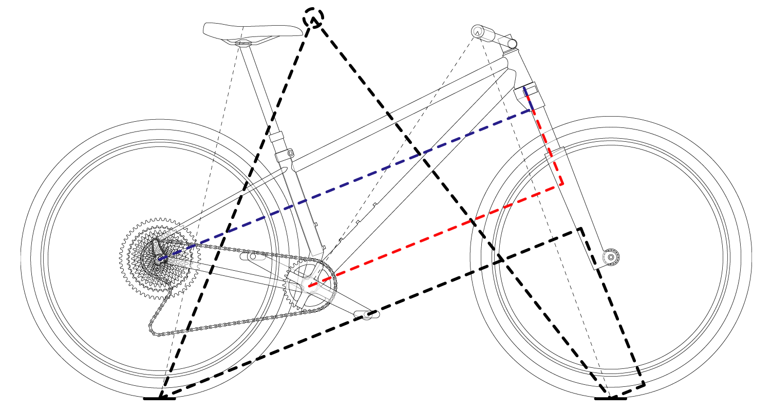
Here this problem shown in a more primitive sketch for clarity:
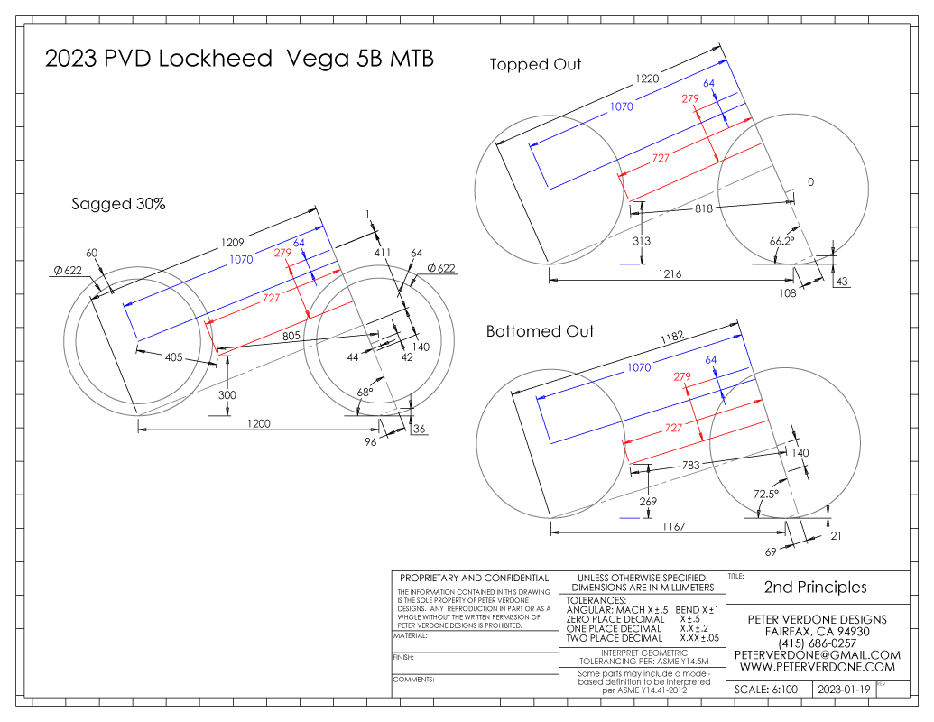
Notice that in the 3 states shown, the CaBar, CaBarOffset, RaBar, and RaBarOffset do not change while many other details that the bike was designed around have. Of course, many discrete points could be invented for this rigid structure. But, the dimensions I describe are highly definable and are most primitive (rely on the least amount of mathematical maneuvering).
If we treat the crank axis, rear axle axis, or the base of the head tube as the origin, X0,Y0,Z0, and we know the angles of the head and seat tubes (driving parameters), we can very easily layout the head tube, crank axis, and rear axle axis from there if we know just three of the values described. This also allows for a change in coordinate system for practical considerations.
We see this principle in use around us. This is the principle that my PVD WOPR frame fixture works on most obviously. It’s part of how my SKYNET and Cyberdyne fixtures function. It’s also what Joe Roggenbuck’s Cobra Creator frame fixture uses. It’s an extremely efficient method that can very precisely position the head tube, seat tube, and rear axle.
So, how do we arrive at these values? By definition, we refer to first principles (driving parameters). Here are the formula in the syntax of most common spreadsheets:
1. CaBar = SIN( RADIANS( DEGREES( ASIN((( FrontRimDiameter/2 + FrontTireHeight) – CrankHeight) / FrontCenter)) + HeadTubeAngle)) * (FrontCenter – (ForkOffset / SIN( RADIANS( DEGREES( ASIN((( FrontRimDiameter/2 + FrontTireHeight) – CrankHeight) / FrontCenter)) + HeadTubeAngle))))
2. CaBarOffset= ForkLength – ForkTravel * ( SagPercent/100) – ForkOffset / TAN( RADIANS( DEGREES( ASIN((( FrontRimDiameter/2 + FrontTireHeight) – CrankHeight) / FrontCenter)) + HeadTubeAngle)) – COS( RADIANS( DEGREES( ASIN((( FrontRimDiameter/2 + FrontTireHeight) – CrankHeight) / FrontCenter)) + HeadTubeAngle)) * (FrontCenter – ForkOffset / SIN( RADIANS( DEGREES( ASIN((( FrontRimDiameter/2 + FrontTireHeight) – CrankHeight) / FrontCenter)) + HeadTubeAngle))) + LowerHeadsetStack
3. RaBar = SIN( RADIANS( DEGREES( ASIN((( FrontRimDiameter/2 + FrontTireHeight) – CrankHeight) / FrontCenter)) + HeadTubeAngle)) * (FrontCenter – (ForkOffset / SIN( RADIANS( DEGREES( ASIN((( FrontRimDiameter/2 + FrontTireHeight) – CrankHeight) / FrontCenter)) + HeadTubeAngle)))) + SIN( RADIANS( HeadTubeAngle – DEGREES( ASIN(( RearRimDiameter/2 + RearTireHeight – BottomBracketHeight) / RearCenter)))) * RearCenter
4. RaBarOffset = ForkLength – ForkTravel * (SagPercent/100) – ForkOffset / TAN( RADIANS( DEGREES( ASIN((( FrontRimDiameter/2 + FrontTireHeight) – CrankHeight) / FrontCenter)) + HeadTubeAngle)) – COS( RADIANS( DEGREES( ASIN((( FrontRimDiameter/2 + FrontTireHeight) – CrankHeight) / FrontCenter)) + HeadTubeAngle)) * (FrontCenter – ForkOffset / SIN( RADIANS( DEGREES( ASIN((( FrontRimDiameter/2 + FrontTireHeight) – CrankHeight) / FrontCenter)) + HeadTubeAngle))) + LowerHeadsetStack-COS( RADIANS( HeadTubeAngle – DEGREES( ASIN(( RearRimDiameter/2 + RearTireHeight – BottomBracketHeight) / RearCenter)))) * RearCenter
The development of my equations has actually informed me (more clearly) of what the true driving parameters are in bicycle and fixture design. I would find that the math was overly complex or ambiguous. Further investigation (and more math and drawings) showed that my assumptions were incorrect and didn’t reflect the most accurate and primitive understandings. Years of refinement gets me to here. If you are learning bike design, learn the math.
If someone has better cleaner math for these values, I’d love to see it. I know my math isn’t the cleanest but it is the real thing and accurate. I also need to figure out the names for these, the description is cumbersome.
These dimensions have real value, in that once the bike is constructed, they are fixed and can be used in modeling the system regardless of the fork that has been placed into the frame, the location within the travel, or if there is a rear swinging arm. Any headset lower, fork, or wheels can be swapped into the bike and this would still be true. Thus, knowing this somewhere in the design process has value later in the life of the bike.
Notice (again) that almost all of the driving parameters that were chosen to produce this frame change when the system state changes, ie. the fork position changes. Front wheel and rear wheel trail are constantly changing as the bike is ridden, The flop and front center also change.
Other original driving parameters or meaningless constructs (such as ‘stack’ and ‘reach’) do not account for this. So, how do we know anything?
This is really important. Almost all of the geometry parameters that we may have used to initially describe the bike have changed. What is constant? Among a few other fixed values like wheel diameter (if those aren’t changed), there are the four dimensions that I’ve described earlier.
Let’s say that you want to be able to calculate the head angle of a hardtail mountain bike at a given percent compression from initial driving parameters. No problem. While any percentage can be chosen, we’ll choose 100% as some frame information at full travel is very useful to the designer. Let Sag%Option = 100. Here, I’ll use the value we calculated earlier for RaBar ( 1070.3mm) and RaBarOffset (64.1mm). Then, we pivot the frame about the rear axle.
HeadAngleOption =
= DEGREES( ASIN(( RaBar + ForkOffset) / SQRT(( ForkLength – ForkTravel * Sag%Option/100 + LowerHeadsetStack – RaBarOffset )^2 + ( RaBar + ForkOffset)^2 ))) – DEGREES( ASIN(( FrontTireHeight – RearTireHeight) / SQRT(( ForkLength -ForkTravel * Sag%Option/100 + LowerHeadsetStack – RaBarOffset)^2 + (RaBar + ForkOffset)^2 ))) =
= DEGREES( ASIN(( 1070.3 + 44) / SQRT(( 551 – 140 * 100/100 + 1 – 64.1 )^2 + ( 1070.3 + 44)^2 ))) – DEGREES( ASIN(( 64 – 60) / SQRT(( 551 -140 * 100/100 + 1 – 64.1)^2 + (1070.3 + 44)^2 )))
= 72.46 Degrees
We now have a very useful, although trivial value. The head angle of the bike isn’t important outside of the mechanics of the suspension and structure of the bike. It’s not very valuable to the designer that wants to know how the bike feels. Here, what is important are the values that we can now calculate with the new head angle, notably, the front wheel trail and crank axis height at any point in the travel.
CrankAxisHeightOption =
= RearRimDiameter/2 + RearTireHeight – RearCenter * SIN( RADIANS( DEGREES( ATAN( ( RearRimDiameter/2 + RearTireHeight – BottomBracketHeight) / SQRT( RearCenter^2 – ( RearRimDiameter/2 + RearTireHeight – BottomBracketHeight )^2 ) )) + ( HeadAngleOption – HeadTubeAngle )))
= 622/2 + 60 – 405 * SIN( RADIANS( DEGREES( ATAN( ( 622/2 + 60 – 300) / SQRT( 405^2 – ( 622/2 + 60 – 300 )^2 ) )) + ( 72.46 – 68 )))
=269.18mm
FrontWheelTrailOption =
= (FrontRimDiameter/2 + FrontTireHeight) * COS( RADIANS( HeadAngleOption )) – ForkOffset
= (622/2 + 64) * COS( RADIANS( 72.46 )) – 44
= 68.98mm
Now we understand how close the chainring, cranks arms, and pedals will be from the ground at full travel. The trail is significantly far from zero (capsize, ala Foale), so we can expect control to remain in the hardest of impacts.
This can be done for any of the initial parameters that there is interested in after the change.
Anyone familiar with using BikeCad or another CAD package could easily produce drawings like I have and figure out these dimensions. That’s not the important part of this post. It’s that THESE are the important dimensions for allowing this and that industrial spreadsheets can be put together that report this information, in several configurations, almost instantly. That’s the power here.
Here’s the thing, when we talk about bike geometry we want to describe the bike. Meaningfully. So that it can be understood in any state or configuration. Having a fixed unchanging dimension does that. This is something that I’m going to be putting more thought into as I look for better ways to do this.