Back in November 2019, I posted a stream of consciousness, ending in an enlightening concept: PVD/RAD. It looked promising even in that primordial state. The problem with that post is that it was confusing and left folks with more questions about the process than the answers it could have.
Six months later, I’m still excited about the process. Sadly though, I have been distracted with several large scale projects and more pressing intellectual work that has kept me from further work on PVD/RAD. I keep referring to it, though, as it is the only tool I know of that does what it does. Each time someone has talked to me about fitting a bike or designing one, we’ve used it…and it’s helped. The time to refine has come.
The goal of this process is to have a tool to determine the ideal hand grip position a particular rider will need when designing (or purchasing) a bicycle for them. Antiquated methods of fit do not work (if they ever did) to place this well for the modern mountain biker. There are a lot of crackhead setups out there because few riders have the drive or ability to improve them. Many riders lack the experience or references to communicate their needs. They may have done very little development on their riding position. They may not have a bike in hand to test with or are so outside common sizes (like our friend Soren) that they can’t test a bike, because it doesn’t exist. Others may be unable to do much with their bikes due to poor proprioception.
This system can be used to describe any bike with flat handlebars. Be warned, the numbers that I provide here are intended for use on bikes with modern geometries. Antiquated designs would need to be described with differing numbers.
We base PVD/RAD on two body measures and two chosen angles. The measures are taken from the riders body to gauge some scale and the angles are referred to by the athletic capacity and goals of the rider. These angles should be able to be translated among riders with the measures adjusting for the riders body type. With this method I can set riders of two different sizes in very similar positions on their bikes. That’s useful and allows a different kind of discussion to begin.
As explained in the earlier post, this is a system based on an approximate and somewhat crude model. The angles we discuss are not “actual” angles of the body and arms, rather they are angles that could be attained in an imaginary case. The angle of the body relative to the ground and the arms from the body were we standing perfectly straight and with straight arms at the extension of the pedals. We simplify the rider because it is impossible without costly and cumbersome data acquisition set up on trail to get any closer. People ride differently. They have different strengths, different fears and different skills. Some want to get to the top of the hill first, others want to be the first to the bottom. Hopefully, we can come up with a way to describe the fit spectrum, catering to the rider’s priority, but also continues to work well throughout the rest of the ride. It also has value in communication and record keeping during development and testing. This is not the last word in fitting and fine tuning will take place.
One of the big problems with my earlier post was the method for determining the ‘body length’ and ‘arm length’. As discussed, the shoulder bears little resemblance to a simple pivot and determining the point of reference is a challenge. Recently, a few friends of mine solved that problem…inspired by an evening of alcohol consumption and the need to order a few Marino frames. Great news!
The solution was remarkably simple; we don’t measure the pivot point. We measure something else and that gives us both the body length and arm length. Shadows cast tell us about the tree!
Below find the process for making this measure broken into very specific and simple steps. Once you understand the concept it should be easy.
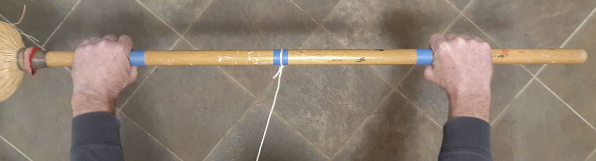
Tools: broomstick, 9+ feet stranded electrical wire (22AWG? or control cable, although quality non-elastic cord can be used), measuring tape, and a friend to help.
- Tie a 9 foot segment of wire (cord) to the middle a broomstick. This should be long enough for most people.
- Measure the distance between your hand placement on the handlebars that you plan on using. This will be approximately the distance between grips. This affects the measure so it is important to be precise. In my case, the value is 540mm.
- Mark this with masking tape on the broomstick so that the wire is centered. Centering the wire between hands helps average any error in tilt.
- Note the diameter of the broomstick, preferably it is a fatter broomstick that is about the diameter of a bicycle grip. In my case, the broomstick is 28.5mm
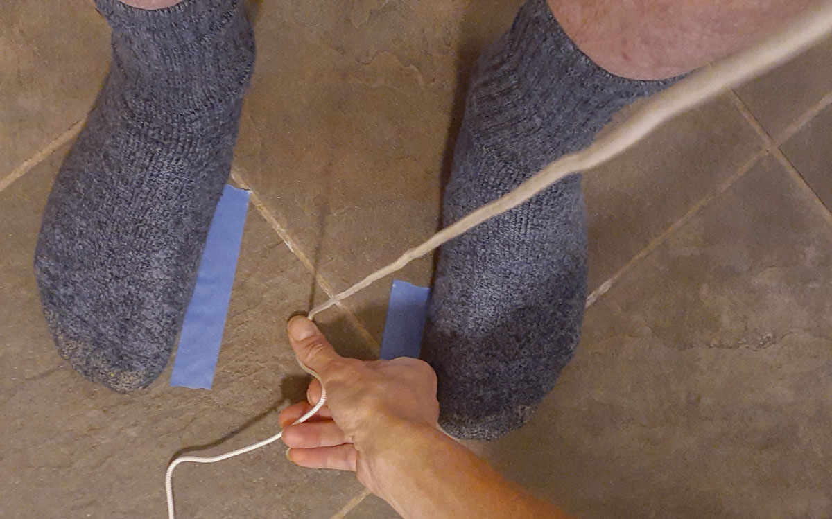
- Measure the distance between your foot placement on the bicycle with the cranks and pedals that you plan on using. In my case, that is about 165mm.
- Mark this distance with masking tape on the floor.
- Remove shoes and spread feet (no shoes) using the tape as a reference.
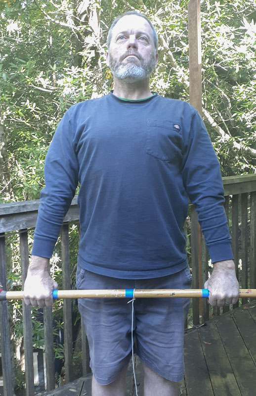
- Holding the broomstick and with feet apart, referencing the tape, stand as upright and as straight as possible and hold the broomstick overhead, as high (and level) as you can, gripping as you would on a bicycle.
- Measure the length of the wire to the floor.
- Holding the broomstick and with feet apart referencing the tape, stand as upright and as straight as possible and hold the broomstick as low (and level) toward the floor as you can while gripping as you would on a bicycle.
- Measure the length of the wire to the floor.
- Add 1/2 the diameter of the broomstick to both these values.
Body Length = (High + Low) / 2
Arm Length = High – Body Length or Body Length – Low

Thus, by measuring the height of our hands in these two positions, we can accurately approximate the measures we need. It’s not perfect but it is reproducible and specific. It’s also something anyone can do in their own homes without any special tools.
Now we need to decide the body angle and arm angle from the body to use in our calculations. I have very little statistical reference for the numbers below as this is early in development but they should produce good ballpark results. Please feel free to contact me with what you learn.
These numbers are for a hardtail with fork sagged or suspension bike topped out:
For trail and enduro type bikes, the body angle should be around 81 to 82 degrees from the ground. More upright will be less aggressive and for folks with weaker cores and upper bodies…or for very aggressive descending. The arm angle from the body will be around 33 to 33.5 degrees.
For XC MTB and aggressive All-road, the body angle should be around 80 to 81 degrees from the ground. More upright will be less aggressive and for folks with weaker cores and upper bodies. The arm angle from the body will be around 32 to 32.5 degrees.
To perform the calculations we also need two more pieces of information about the bike chosen, the Crank Length and the Sole to Pedal Axis. Crank length is obvious. The sole to the pedal axis will be the thickness of the insole of the shoe, the sole of the shoe, and the distance from the top of the pedal or cleat to the axle. For common shoes and SPD pedals, I chose a value of 15mm. This is worth looking into for best results.
So we describe the hand grip location by calculating the radial location then the cartesian location from the crank axis. Formulae below are formatted for use in common computer spreadsheet software.
Let:
Body Angle from Ground = B2
Arm Angle from Body = B3
Body Length = B4
Arm Length = B5
Crank Length = B6
Sole to Pedal Axis = B7
Crank Axis to Grip Radius = B8
Crank Axis to Grip Angle = B9
Crank Axis to Grip X = B10
Crank Axis to Grip Y = B11
So:
Crank Axis to Grip Radius = SQRT((B4+B7-B6)^2+B5^2-2*B5*(B4+B7-B6)*COS(RADIANS(B3)))
Crank Axis to Grip Angle = B2-DEGREES(ASIN(SIN(RADIANS(B3))*B5/B8))
Crank Axis to Grip X = B8*COS(RADIANS(B9))
Crank Axis to Grip Y = B8*SIN(RADIANS(B9))
Now, for designing the bike, we take these values and apply them to the end of the handlebar at the grip. The roll of the bar, the chosen head angle, the stem, the headset and spacers need careful consideration as we work back to get stack and reach numbers for the frame that are common for constructors and manufacturers to use.
Let’s look at my 2018 Warbird frame.
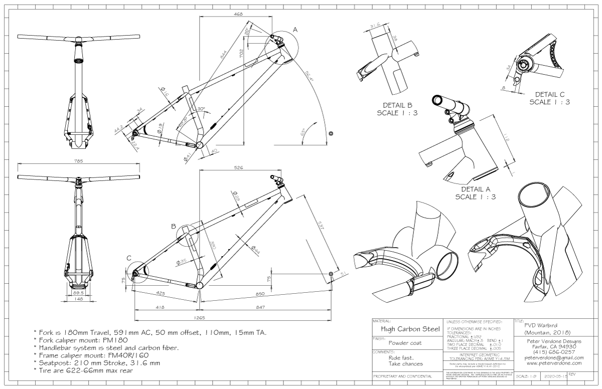
Focusing more on the measures being discussed:
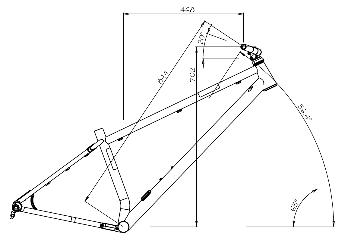
The result of my inputs is in this frame. This is where the fitting of the mountain bike will begin.
Obviously, this process can be reversed by measuring the position of the grips on the bike (as I did to develop this) and working backwards to get the body and arm angles. This will help you communicate what you have and how it’s interfacing with your body. Knowing that, you can make some decisions of where you want the fit to change.
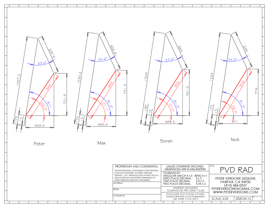
So, my buddies that figured out how to get the shoulder pivot location are all fairly tall, especially Soren. So fits and bikes worth testing aren’t easily available and anything that is, is drastically antiquated design-wise. This is exactly where this system can be useful. We can develop a fit without a bike in hand. At the very least, PVD/RAD will get them a lot closer than they would with the limitation on testing they otherwise have.
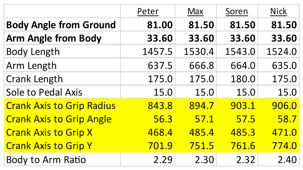 (arm and body length are transposed above and in next. Will correct in the next image edit.)
 Comparing several styles of bike is usable also. Here I sample some bikes of mine that I’ve mentioned: the Warbird, Spitfire, and Airspeeder (the enduro hardtail, the krunker, and the aggressive all-road bike, respectively.) You can see that the big factor of change is the rock of the body: more upright on the casual attitude of the krunker and laid down more for the speed of the all-road bike. Slight changes in arm angle occur depending on the need to drive hard at the right time. As future bikes are developed and this modality is used from the start of the design process, further improvements in predictability of the characteristics and performance of the bikes should develop.
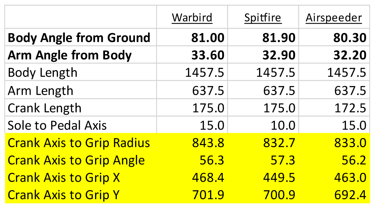
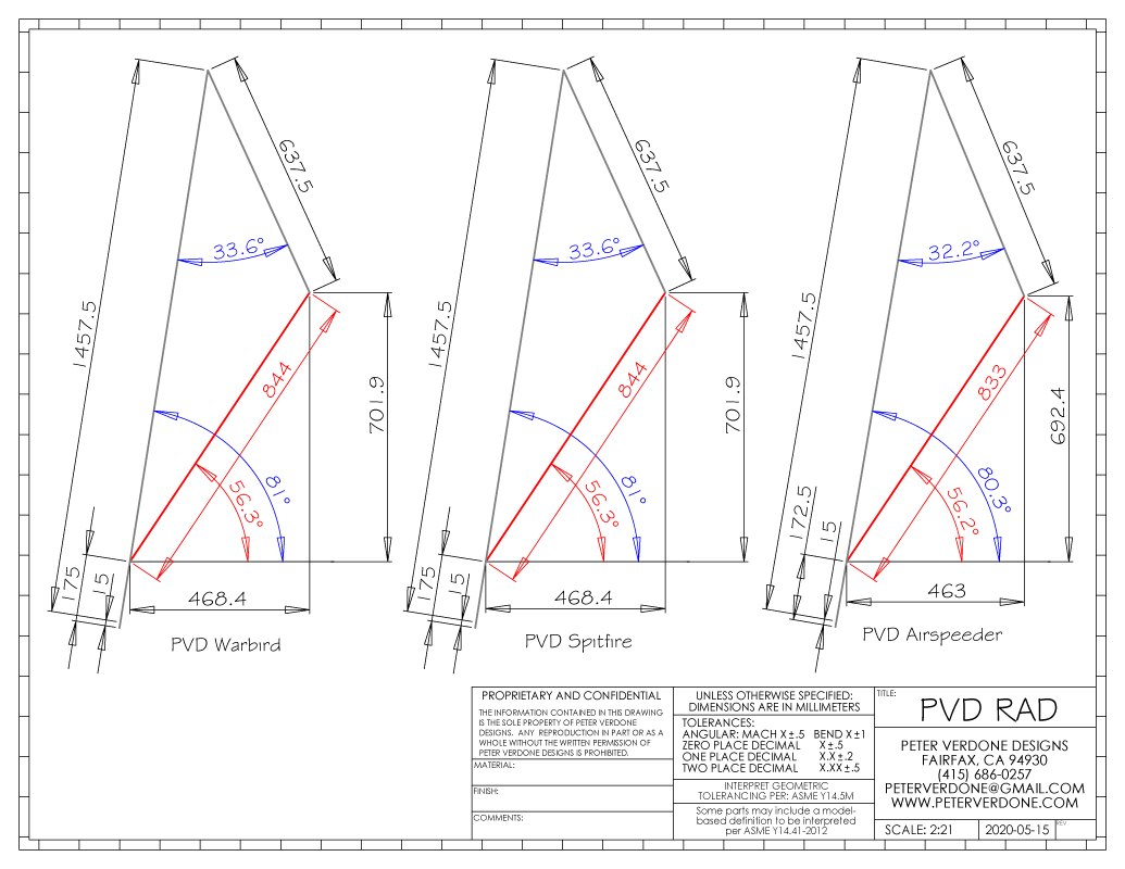
One problem that I have is that I’m working with a very different type of bike than anyone that I know. My Warbird, Airspeeder, and Spitfire are more progressive in design than any other bikes I know. The riding positions that I’m capable of using at speed and safely are not the same as what can be done on commercially available bikes. Still, I’m an old fat guy that isn’t riding at a professional level, which tempers some of that.
Similarly, people on antiquated bikes will be forced to use different body positions simply because the geometry, parts kit, and stability of their bikes won’t allow for moving weight very far ahead of the rear wheel. Numbers I’m using for progressive MY2020 chassis won’t apply to regressive MY2020 bikes or MY2010 bikes. This is all part of the equation and needs to be recognized when building a database.
For this reason, others need to do work with system and figure out a rubrik that has a set of values that are workable in different modes of design. From box stock showroom product with a novice rider to highly developed race machines with professional riders piloting them.
2021-03-14: Ben Land posted a video the other day that could give folks some useful tools in this realm. It’s worth a watch and he posts a calculator for arriving at measurements as they are on the bike.