The rise of the machines…
TL;DR: This isn’t just another Arctos frame fixture clone. It’s a better solution and one you’ve never seen. The rules of the game have been re-written.
If I were to say where this began, it would probably be back at the 2016 NAHBS show in Sacramento. I had spent the prior few years riding big suspension bikes as hard as I could, and drawing them and geeking out as I usually do. I had been looking to where bicycles would evolve rather than where craft/handmade bicycles were going (nowhere). I had a frame sitting on my fixture during this time but every time I came back to look at it, my ideas had changed. I started over three times.
One of the (many) problems in the handmade bike world is that as a person starts making frames, those become all they ride and their references get stagnant. Not surprisingly, most bikes shown at NAHBS tend to resemble mid-nineties (or older) bikes rather than those of the current era. Few builders can spend both time in the shop and time testing new concepts.
I was seeing bike design changing so fast and I wanted to discuss this with others. But I spent the weekend drawing blank stares, seeing people who knew nothing about mountain bike design (or bike design in general) vying to win an award for their ‘mountain bike‘ or judges that simply weren’t qualified to judge that room. The witch doctors and charlatans in the industry around me were frauds who had no idea what they were talking about.
My sheer disgust after leaving the 2016 NAHBS show drove me to go all in and remove my excuses for not producing the bike I was looking for others to make. I brushed several years of dust off my fixture and the work hasn’t slowed since. The Red Five era began, marking my entry to masterwork in bicycle design. This was the best thing I ever did with bikes, all in.
The big problem I had at that time was the need to properly place bent seat tubes in my Anvil Journeyman 3.1 fixture. I had made it work for Red Five and a few little play bikes before it but I needed a real solution for Pink Five as it was clear that most dirt frames will now need this feature. It wasn’t possible to place the tube with great precision on the Anvil fixture. After a deeper dive at a solution I drew up a change which I presented to Don Ferris (Anvil). We argued about it. I won. The result is Don’s Anvil PVD Offset Seat Tube Tower. It has since been copied in several other fixture designs. It also points to the heart of the solution I come to today.
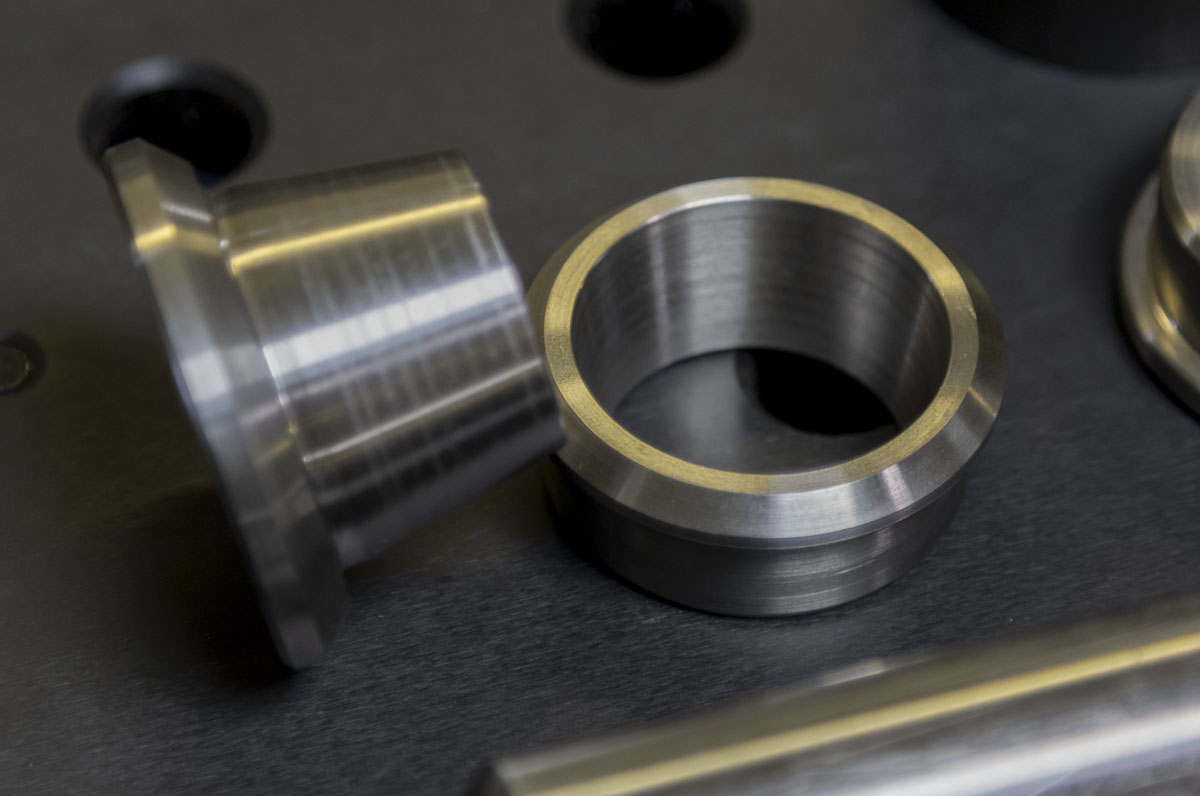
That was the start. I kept designing, changing, and refining everything that I was doing. Numbers were used from my testing on the trail. On paper and during construction everything was changing. This wasn’t for craft but for my engineering goals. I didn’t need a prettier bike. I NEEDED A BETTER BIKE. I paid a lot of money to have special frame parts cut for me. I designed improved brake mounting. I was constantly frustrated that the way of doing work that made the most sense to me wasn’t possible with the frame tooling that I had. I made things work. I got by well enough but not without lots of work and frustration solving problems that should have been easy.
While constructing the Supermarine Spitfire (late 2019), I hit the limit of what I could with my current tooling. With a frame reach of 576.4mm, low fork, and a head angle of 65 degrees, this chassis had the most projected head tube of any bike that I had ever made. The entire adjustment range of the Anvil fixture was used up. The head plate was only being held by one of the two sets of bolts and hung precariously off the end of the base. This was for a klunker chassis built for a rider that is 5’10”. Any more advancements in design or a bike like this for a rider taller than myself and the fixture would be unusable.
I had come to the end of the road with existing tools and was now truly on my own path. Nobody was there to help me with this problem.
“They told us not to ask where they got it. It’s scary stuff. Radically advanced. I mean, it was smashed, it didn’t work, but it gave us ideas, took us in new directions, things we would’ve never th… All my work was based on it.” –Miles Dyson
I kept thoughts about the fixture in the back of my mind for a few months while I was working out some technical issues that arose in my handlebar design. Once that had been resolved I had to tackle the fixture problem. Without a new fixture, I was DOA.
I began as good solution-finders do, by backing everything up to first principles. What was needed for a proper suspension bicycle and moped fixture? When you look at most of the fixtures that have existed, they are primarily based on turn of the century (1900s) lugged construction and design. They were optimized for work with open flame, like an old-time blacksmith would use. The forms that the tools have taken are generally derivations and refinements on that process. The adjustments of the fixtures that exist may seem obvious but that’s because that’s the way it’s always been done. That’s the way that everyone has been taught.
I have seen an aversion to using math or any rational methodology in the design of a bike frame or setting of a fixture in the cottage framebuilding world. This is a real and significant problem and (along with production carbon fiber frames) has slowed advancements significantly. Few people that build bicycle frames are proficient in trigonometry or the use of calculators or CAD. Most fixtures are set using the most obvious numbers that describe a bike on a retail showroom. While this seems sensible to most technical novices, it leads to poor solution finding and limited development of the frame’s design. Most of those retail numbers are truly meaningless from a chassis design perspective. These days, we can do very complex calculations even on the shop floor allowing us to work at a much deeper level of design and construction. The ease of these complex calculations are now at the level that everyone now has a phone in their pocket capable of magic.
![]()
Fixtures for making weldments have different qualities in different environments. In high production, we would use a dedicated fixture for each frame size. Holders would be bolted or welded into place so that it would be impossible for the position to change. This makes everything easier and foolproof. You don’t want easy adjustments in a high production environment. Easy adjustments lead to costly mistakes and a loss of valuable time.
I have long been paying attention to what is done by major manufacturers when they build frames. Back in 1995 while passing through Wisconsin, I was given extensive tours of the production facilities of the Trek’s Whitewater and Waterloo plants by their respective production managers. Not in a tour group, just me and the production managers and all the technical questions I could ask. This was just before they moved all metal bike production overseas. I don’t know how I conned my way in there, but I did, and was rewarded. I saw some of the most amazing bike construction and production design there. Coming from the cottage industry in Boston and Fat City Cycles factory at it’s peak, this was a whole different world. They were taking in straight gauge steel from True Temper, butting, swaging, and bending it in-house. They would laser cut a full tube set for each bike at a time to feed production. It was AWESOME! There were a ton of little details that I’m sure I’ve mostly forgotten…but not the frame tacking fixture in the welding area. They were using a plate with a variety of numbered holes in it. On a cart sat pinned tooling for each size and model frame. To change over, you pull the #14 tools from the plate and drop in the #15 tools. Everything is perfectly modular, preventing mistakes and saving time. It took less than a minute to change model or size.
Dedicated fixtures are great for high production but in the cottage industry and for home gamers, this type of fixturing is far too expensive in both time to produce and materials cost. In an environment where every bike is different from the last, it makes no sense to go this route. We want an adjustable fixture that will allow virtually any chassis design to be produced. Maybe a little fussing with setting the fixture is spent but the value in being able to do another design right away without making new tooling is huge.
Looking at a fixture design from the origins, I need to consider not only better ways of solving common problems but understanding where it starts, from the fundamentals of the bicycle. What is different about modern bicycle construction from that of the past? Certainly, a modern understanding of the driving and driven parameters of the chassis leads to a change in perspective for adjustment. As stated earlier, we use bent seat tubes in most common-sized performance designs, but what else? Rear suspension, precision brake mounts and pedelecs. These have needs that previous solutions don’t help with. Producing a rear suspension bike has very special positioning requirements for defined kinematics. This is critical for the system functioning as intended. Caliper mounts for disc brake systems have developed and the needs for fixturing them have outpaced what is easily done off the table. A real solution is needed that is defined by the frame centerline. On mopeds, we are mounting a motor but also batteries and multi-section tubes that need to be held in place in very challenging ways. These cases point to the need for tooling of the fixture to be kept clear of the crank axis area and for a positioning raster to build locating tools from.
How?
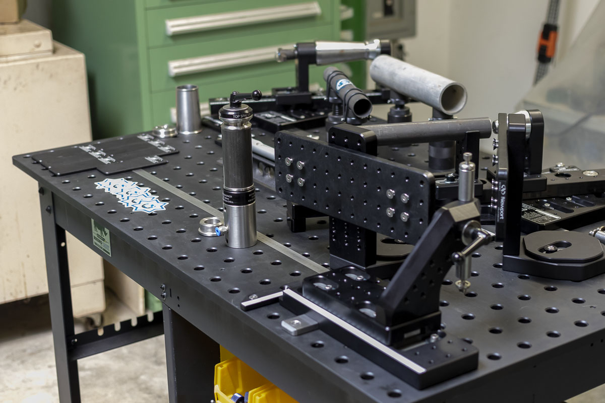
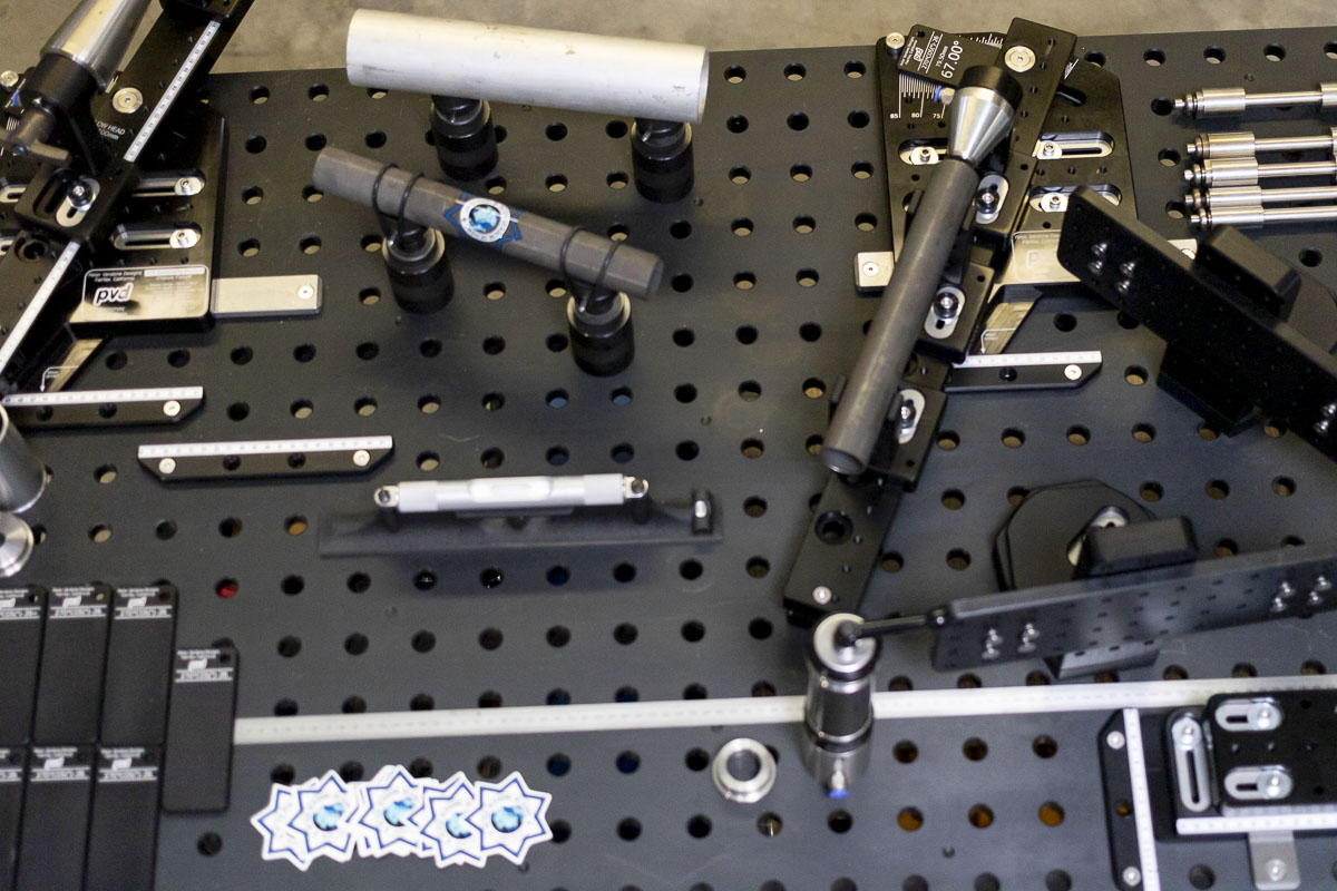
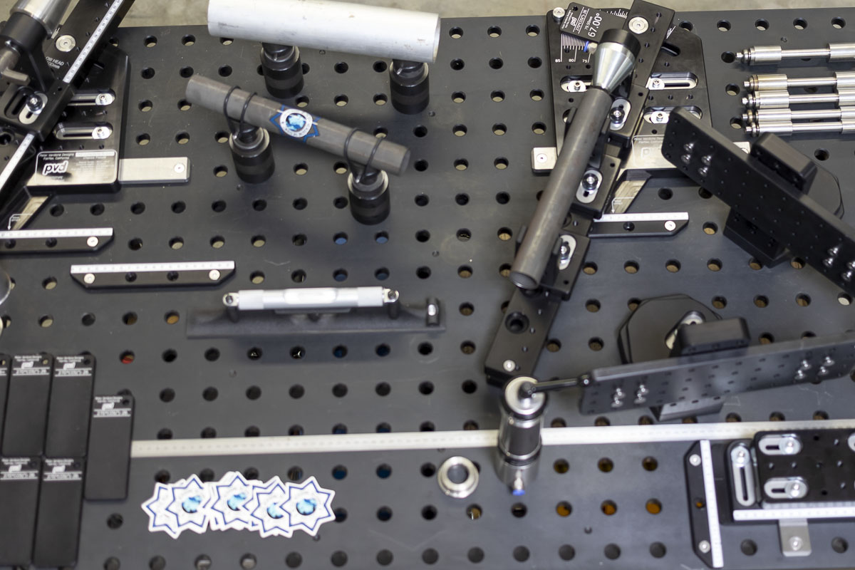
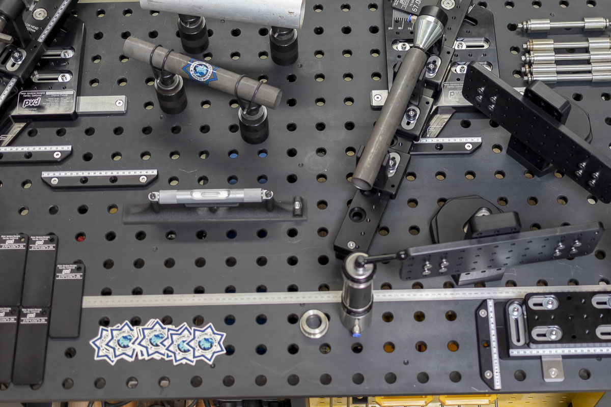
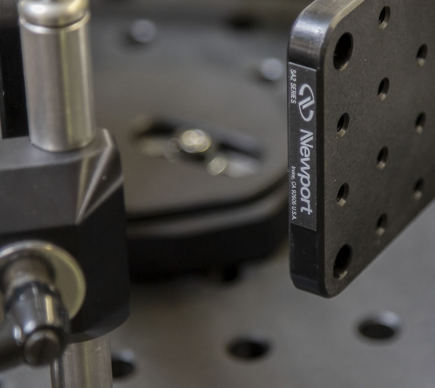
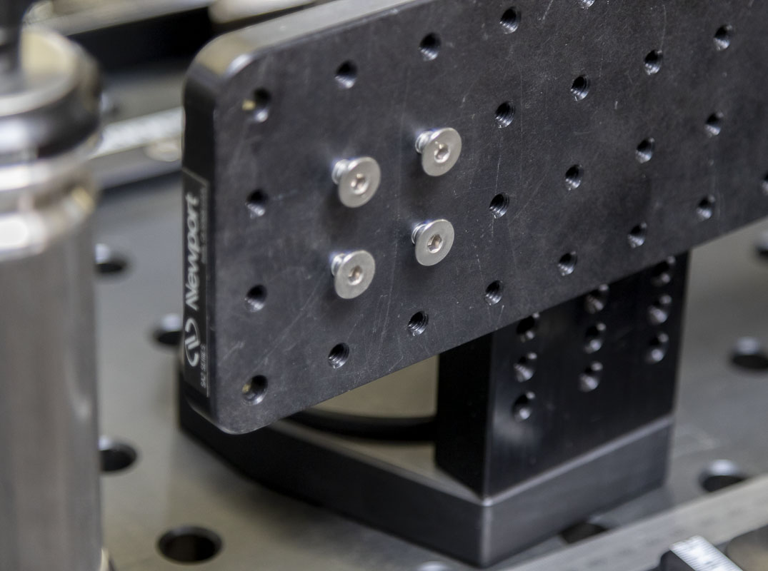
Breadboard. In my professional work at San Francisco State University, I’m supporting several research labs that are doing all manner of experiments built on large (often Newport brand) optical breadboard tables. These are experiments using optics, lasers, and microscopy. I’m often building out special setups on these large tables to make a large staging microscope or send backwards into a cryogenically cooled microscope. I also do work for labs in other departments in the College of Science and Engineering when they need to call in the big guns. It’s very interesting at times.
A while back, I started using small 1/2″ aluminum optical breadboards in my bicycle tooling. This is a component that is common in scientific research and what I’ve been using for my special tools. Building up special holders for segmented rear ends and 3D structures my handlebar/stem system. It was getting easier as I learned how much I could get away with, especially if I was machining 82° countersunk screws to act as both fastener and pin locator. Yes, this is considered an engineering mistake but it works well in bicycle fabrication. If you machine a countersunk fastener to be a true conical pin on the precisely made breadboard, it can and does work for precise location and fastening. Sorry if that hurts the feelings of the purists.
This was all nice for small tools. As things get larger, the costs of the boards go up as does the loads that they will see in service. A larger scale application was looking to be a ways off.
This spring, at about the time that I ran out of room on my fixture, I was looking to make improvements in the shop at my work. It was time for a real fixturable welding table. I needed more capabilities in the shop and that was one thing that was really missing. I shopped out a lot of options. I needed something with a small footprint that would have a good range of utility. I also needed it portable in the shop and keep the cost down.
If I was able to find a welding table that had holes at a 1″ or 2″ raster rather than a 50mm raster (Seigmund) I’d be able to translate any tooling I make on a smaller 1″ x 1″ x 1/4-20 breadboard plate to the welding table. Cutting fixtures could become welding fixtures. If I got just the right size, and it was steel and thick, it would make a very good platform for a frame fixture. I was looking at this as a designer and as a fabricator with a limited shop space and a budget. I needed value in table and in my fixture. A bicycle frame fixture eats up a bit of shop space but also money and opportunity. If instead space and money was put into a welding table and the fixture seen as tooling for it, a lot of birds could be killed with only a few stones.
In a perfect world and in a zero compromise environment, a metric table would be far better for bicycle construction. This would make so many of the adjustments easier, especially when setting up positions other than what I’ve initially specified.
I was figuring that fab shops with 2″ rasters would be where a fixture like this would be a cheap addition. If the have a full fab table already, a few thousand dollars on a bicycle fixture is an easy buy. If you need to source a board, salvage market will be mostly imperial.
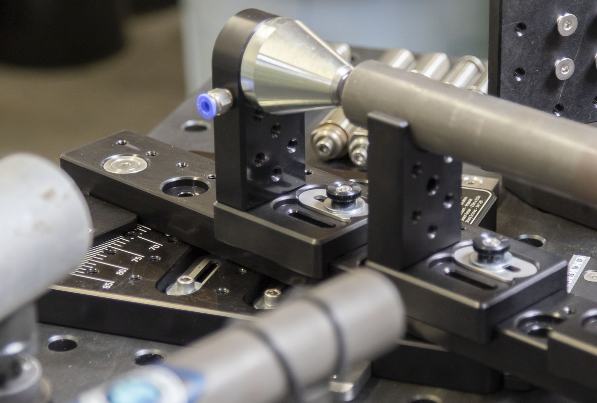
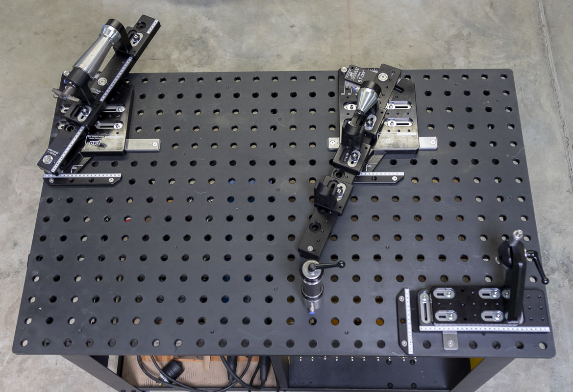
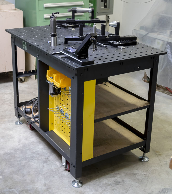
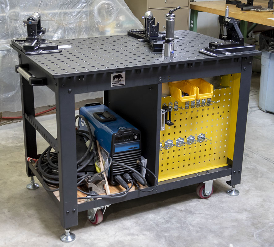
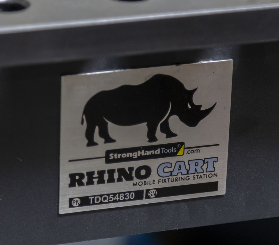
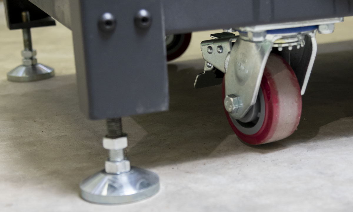
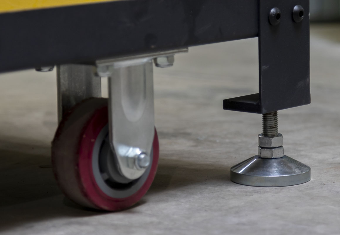
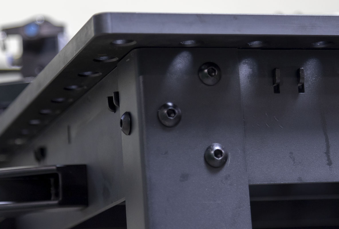
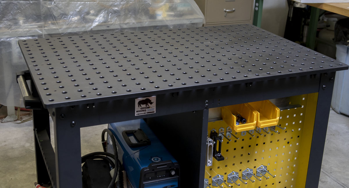
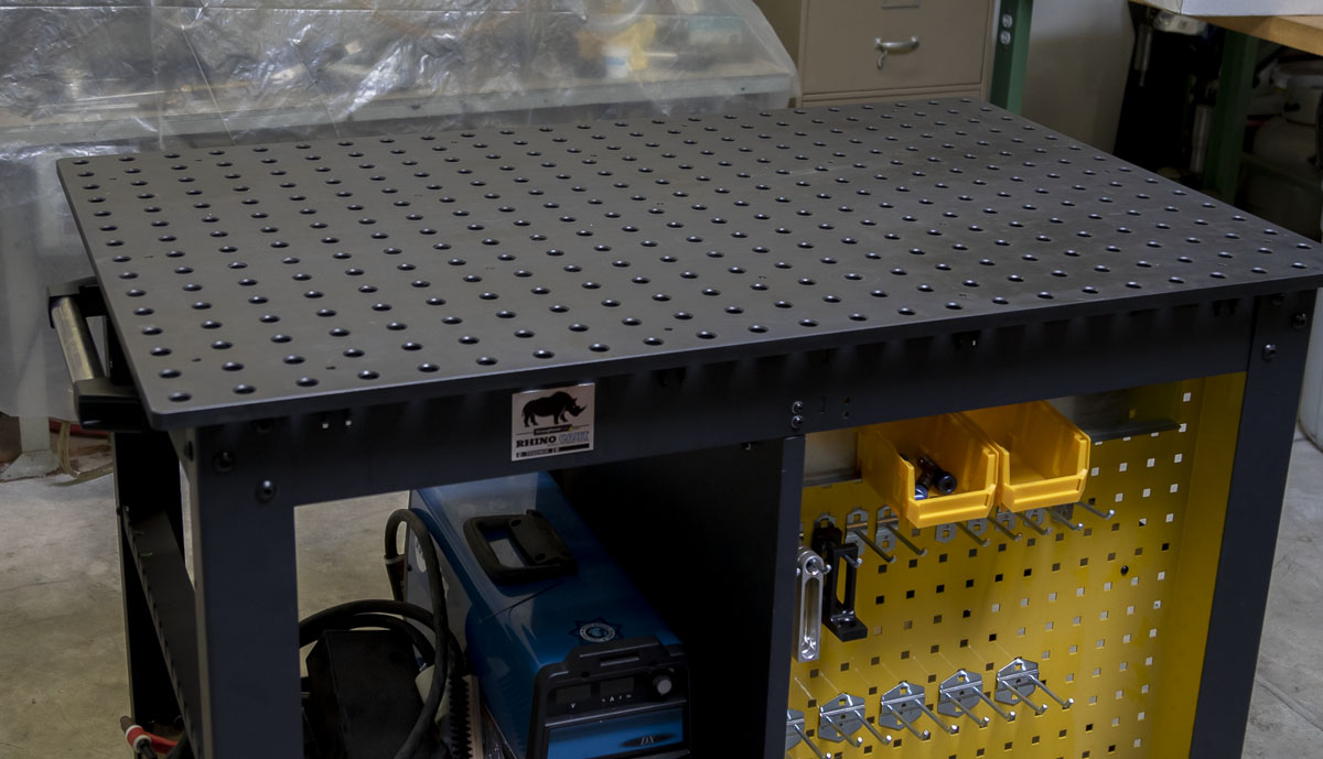
I ended up buying what may be the perfect platform, a RhinoCart. This is a pretty awesome tool. It’s a 48″x30″ steel surface on wheels and with jack stands. The top is ground 16mm thick and has a 2” x Φ5/8” raster. It’s a tidy unit that doesn’t eat up a whole shop. There’s (now) even a metric version. The tool is on heavy duty wheels but can be raised up and leveled on sturdy jacks when fixed. At $2600 cost for the full kit, this is a significant purchase but only half of what a frame jig costs.
Going with the RhinoCart gives me the ability to use all of the fixtures and attachments in the Strong Hand Tools BuildPro catalog. There are a ton of great tools in there that connect directly to the table. The prices are good. It’s worth a look.
Here’s a good video on YouTube comparing several shop welding table options. I link directly to where the RhinoCart is discussed (30:58). While in the video the inspection shows a 0.010″ deviation of the surface. With some shims placed well in the bolting the table down, that can be eliminated. The cart uses a plate that could be nudged true as opposed to the 3D cast plates.
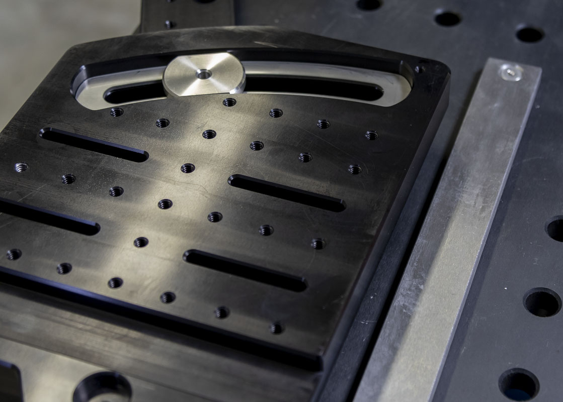
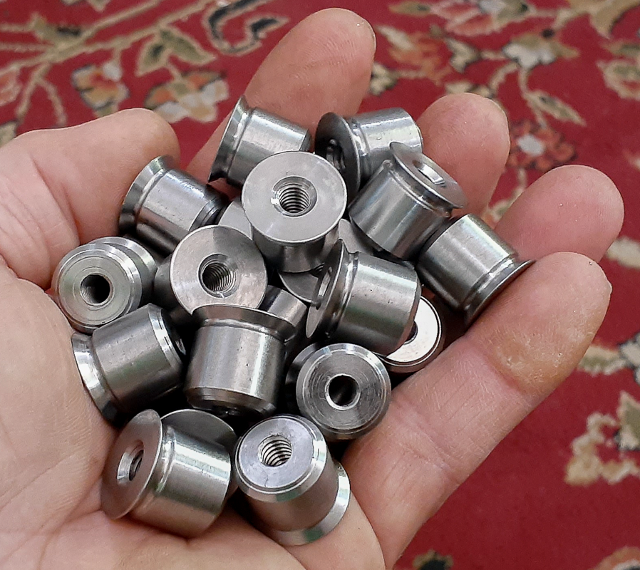
Here’s the magic, once I got this tool in the shop I inspected the raster. It is very precise. Basically, within a 0.001″ precision across the raster as it was machined via CNC in one operation. It’s a breadboard but it doesn’t have 1/4″-20 threads that are especially useful for what I envision. That, of course, can be changed. I designed a nice little precision plug to go in the holes that converts the welding surface to function like a threaded optical breadboard. Now, anything that I make to work with a 1″ x 1″ x 1/4″-20 pattern will work on this table as well provided I have registration on the 2″ pattern. This system can work!
Were I living in a perfect world, I would have purchased a Siegmund Professional Extreme 8.7 – 1500x1000x100 welding table. I don’t live in that world though. While the table is a much more useful size and has side walls to fixture from, I just don’t have the space or budget for such a thing. It’s also produced with a metric raster that isn’t exactly what I wanted. I do love these tables and am jealous of those that have them. Also, in terms of ease to work around as a frame fixture, the RhinoCart top is a lot nicer and will have less table to lean over when in use. I think that the perfect top for my use would be 1300 x 1000mm.
So, having a foundation on the RhinoCart I started to design a surface table type fixture. Many may immediately complain that they prefer a vertically-oriented system. I can’t argue with a preference but there is a huge opportunity cost to getting that, also, what is really gained? Having a full surface to reference anywhere on the frame is a real boon in capability. I can easily build an endless set of custom tools that reference a centerline and can be positioned how I please. Many builders use flat table construction and they don’t do a lot of complaining.
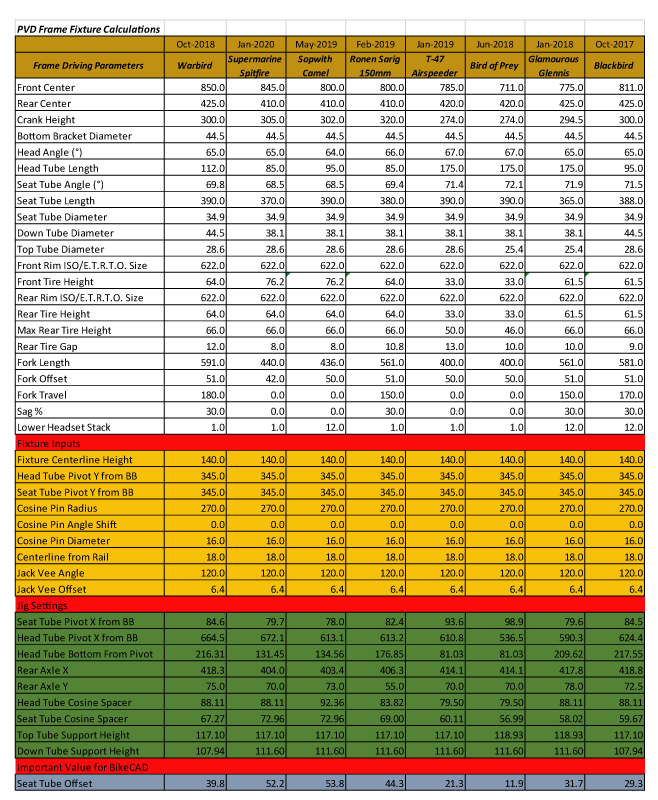
To design a tool, I needed data to define where the fixture would need to function based on what was happening with modern bike design. I produced a spreadsheet to survey the geometry and construction data for the most notable bikes that I’ve built and a few from other major manufacturers. I sampled road bikes, kids bikes, enduro bikes, and klunkers. I looked at bikes for very tall people to very small people. Here is a sample of the last few bikes on the list, there were too many to show all of them. In the linked spreadsheet above are the design driving dimensions (white). These define the bike for how it will be used. The driven dimensions (blue) tell us more about the bike that may be handy to know.
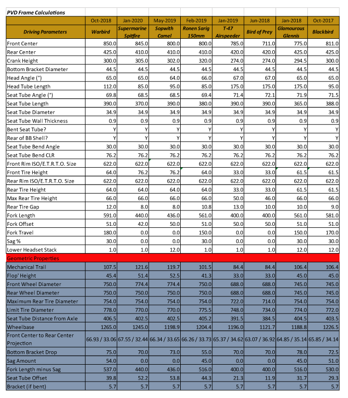
Now below, in blue, are coordinate locations of various parts of the bicycle relative to the ground and also relative to the crank axis. This was needed to understand the actual space a frame takes up on a fixture.
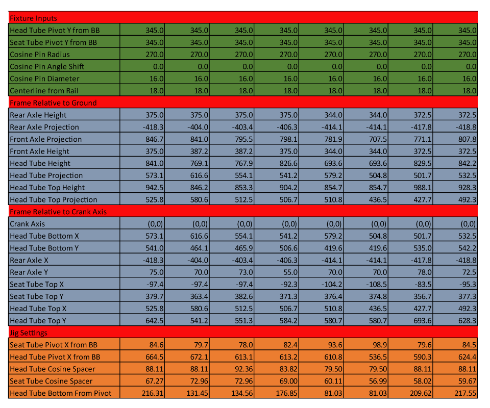
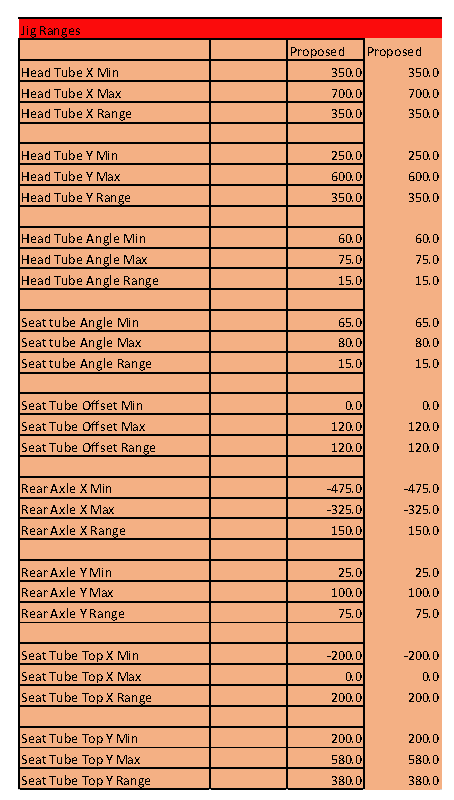
Going through this exercise gave me maximums, minimums, and ranges for what I needed to be able to produce with the fixture. I used this to inform me of my past and I projected into the future and unexpected cases so I could do anything that came up. This would all fit on the top of the RhinoCart if I was very elegant in my work.
In designing a fixture for use on this on this table, I refer to the tooling I developed for the offset seat tube and it points to where this started. I needed to find a way to produce a seat tube angle from horizon and an offset from the crank axis without a direct mechanical referencing of that location. I worked through a variety of virtual pivots and messy design solutions. These took up significant real estate on the table and cost in materials and machining. I was asking some folks for ideas. Ronen told me that the solutions that I was applying were terrible and overly complex. It’s nice to have someone around that will be straight with you and tell you when you are sucking. There had to be a better way. I was perplexed. I couldn’t see it. How? How to make it simple? How to make it easy? How to make it accurate?
Like so many ideas, it came during a mountain bike ride. My head clears on rides and I get into a meditative state. Not for the whole ride but at times. The ride gives me a reboot. I wipe my cache and re-install variables. This re-orders them or has me question their place on the list. Giving room for a new solutions.
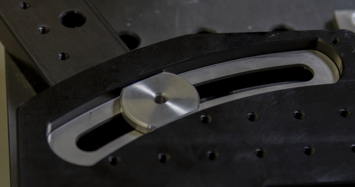
I didn’t need a virtual pivot! It was suddenly clear in my mind that didn’t need to directly reference the crank axis. If I had a coordinate system, I could define an angle from anywhere on the table provided I could calculate the lateral and longitudinal location of the angle pivot from the crank axis. If the lateral (Y) position is fixed, the longitudinal (X) location can be defined on a slide. It’s actually quite simple. This gave me the solution for the seat tube mechanics.
Moving to the head tube yielded another false start. I looked at the solution simply, like everyone in recent years has. Jeff Buchholz’ Sputnik Frame fixture is really awesome. I’ve always loved certain things about it. I contacted Jeff, whom I’ve known since 1990, the Fat City days. I wanted to buy 1/2 of his fixture. The head tube section and the rear axle section, nothing else. Jeff was not down. He wouldn’t sell me a partial fixture. The whole fixture or nothing. We went back and forth. Nothing was what it was going to be then. Strong wills collide.
Since I couldn’t just buy the head positioning system, I needed to design something from the ground up. Suddenly, this had become a much larger project than I originally intended. These are turning points, when you face a decision; the mountain climb or the lazy slide down. Just like on the best mountain bike rides, when you get to an intersection turn uphill.
I needed a fixture to hold the head with precise longitude and latitude adjustment, high resolution angle adjustment, and true centerline height. That’s either expensive or terrible or both. The cost kept multiplying and the design was very messy. Worse, it ate up a ton of room on the table. I didn’t love it at all. I couldn’t go this way. I needed to look at this fresh. What if…it came to me, the head isn’t much different from the seat, it just has a specific height offset from the from axle in addition to the offset for the ‘rake’ or fork offset. Why not just use the same system I’m using for the seat and keep the BOM down? Voilà. The pieces fell into place from there. More common parts. More adjustment range. More cheaper and more easier. This is when you know you are doing good engineering.
At the rear axle, there isn’t much. A small longitude and latitude adjustment. With creative tick marks, The design can be flipped and extended or retracted to produce rear centers for 8″ push bikes up to gigantic Kamikaze lengths. The trick here was just making sure that all axle widths could be used and that hangers or brake tooling had space to be set up.
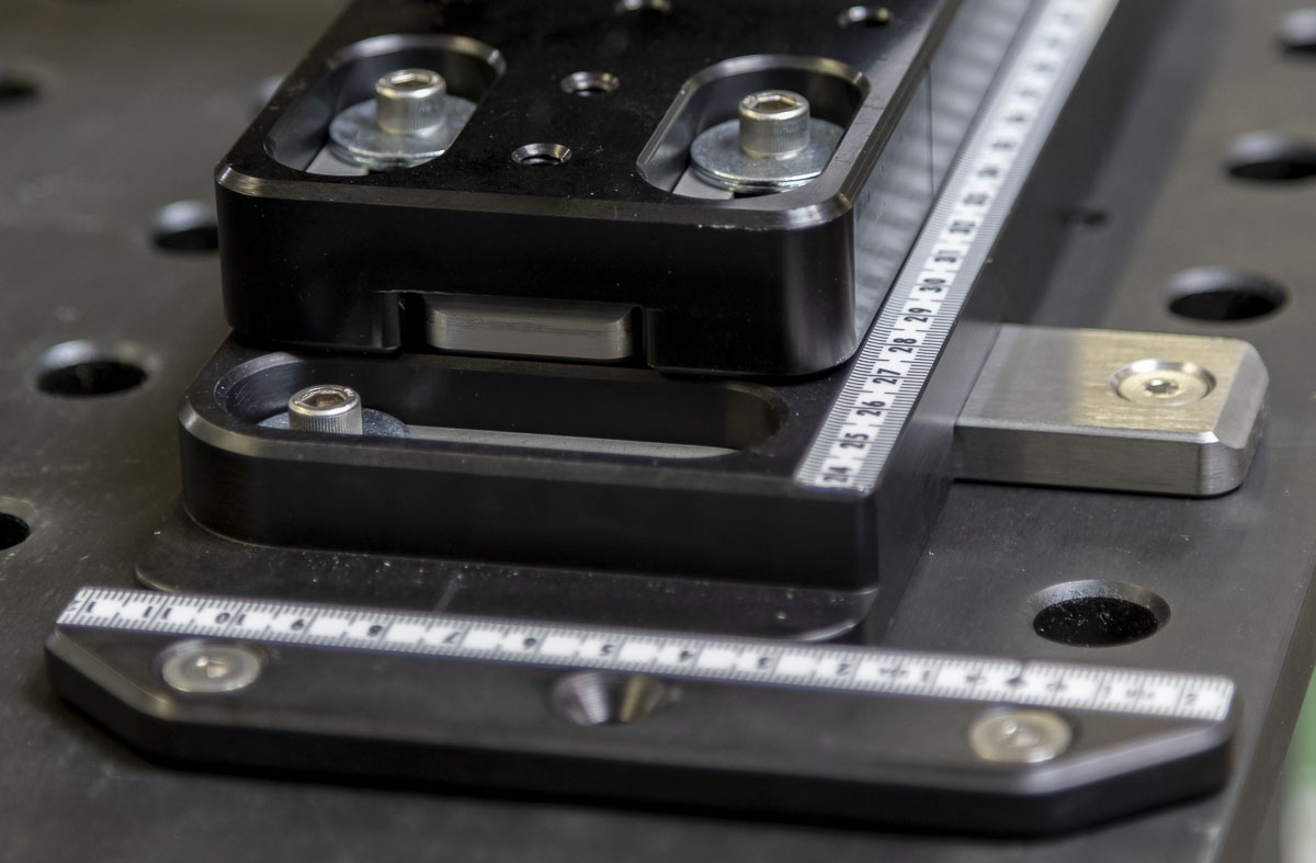
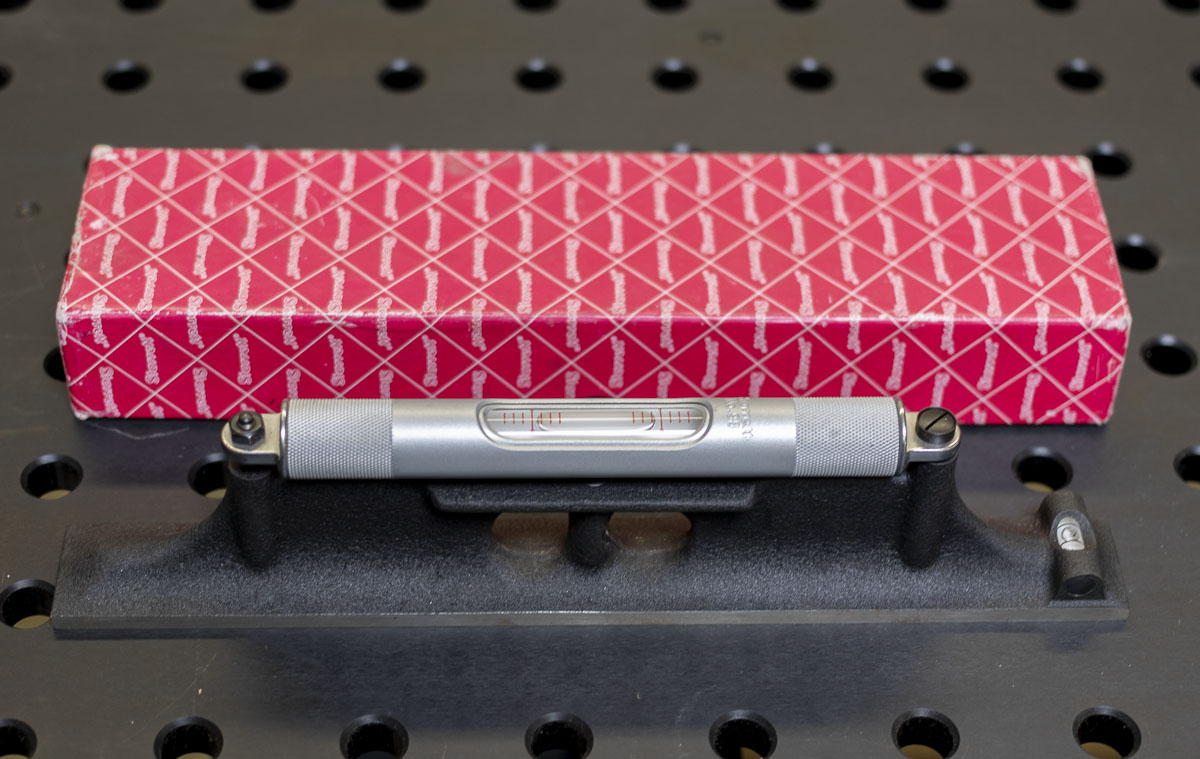
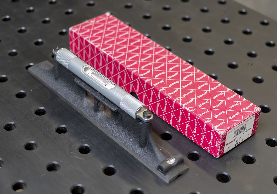
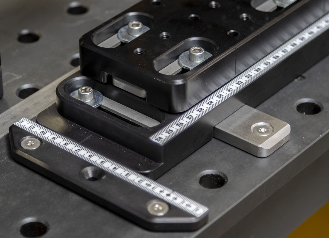
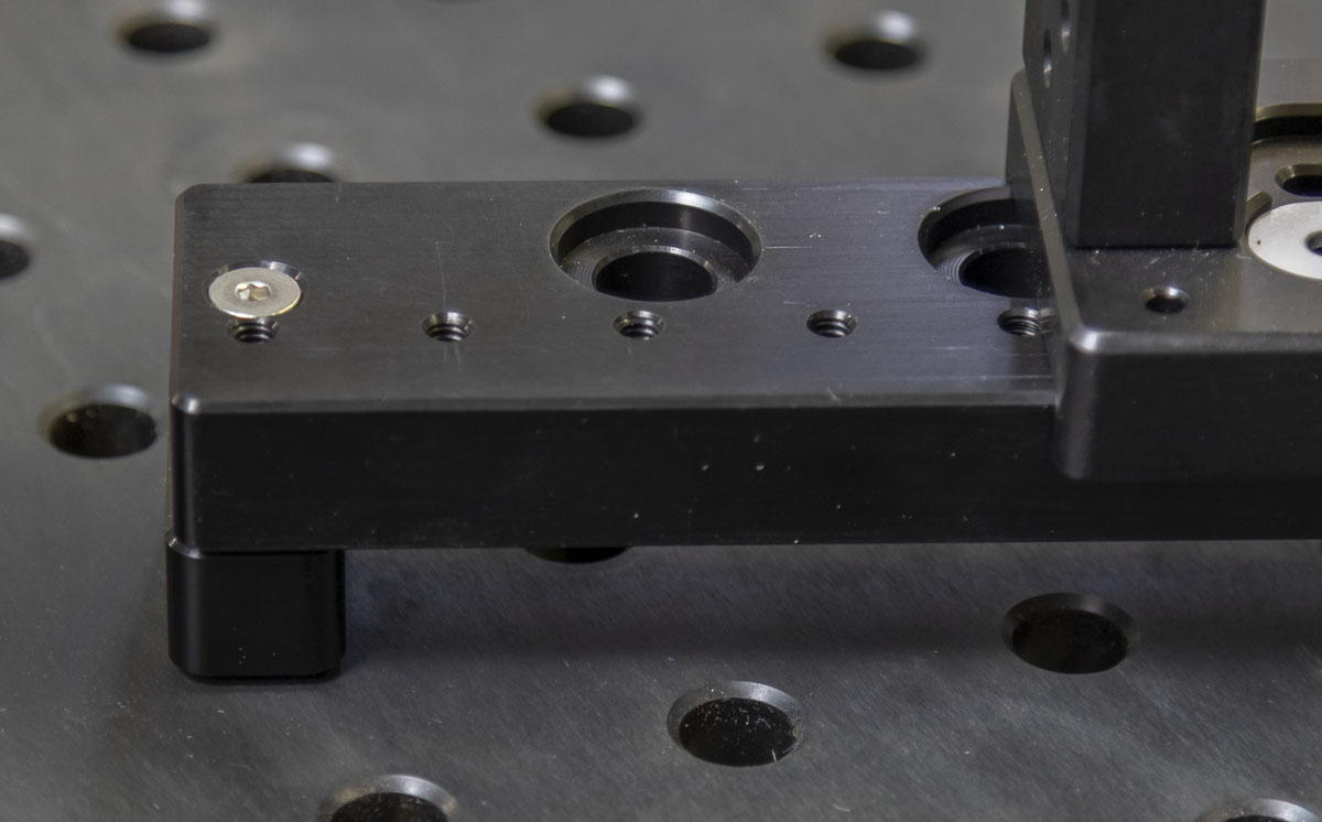
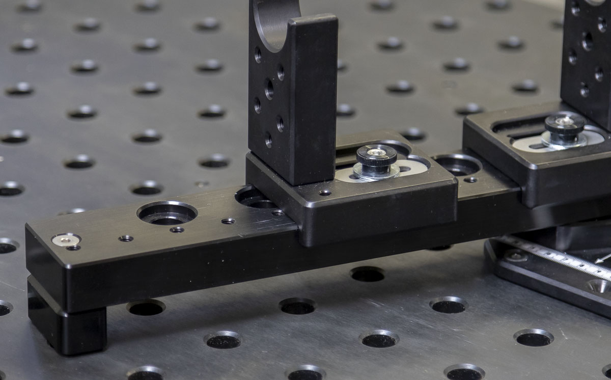
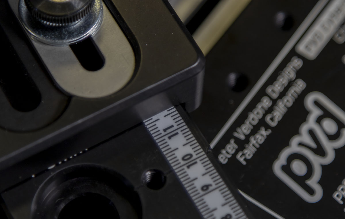
The sliding axii on the table are defined using a 1 1/4″ wide, 3/8″ thick Starrett A2 tool steel rail. This is a very simple system but it does require a fairly tight tolerance in the placement and width of the slot on the plates. It is incredibly robust and smooth in action.
I decided to keep the centerline height low for this draft of the tool. 140mm off the table would make it easier and economical to produce tooling. I checked this against any of the widest fat bike arrangements and it would be fine.
To use the fixture, a bike is designed properly in a program like BikeCad or a solid modeling platform. I like to get my fit details sorted in BikeCAD as it is excellent for this, I then move to SolidWorks to design the chassis and parts with the geometry from BikeCAD. This gives the driving parameters that the frame needs. From there, I enter data into the calculator (MS Excel) that produces very precise values for setting the fixture.
This spreadsheet is a bit different than the sheet shown earlier where the goal is not to collect data but refine it for use. We know the driving dimensions and the fixture geometry, we have to calculate the needed settings. It’s clean and efficient. The only extraneous information shown is the seat tube offset calculation that comes in very handy during the design of the bike frame in BikeCad. (Brent, fix this!!!)
By having actual frame design values entered, all of the calculations in the spreadsheet refer to these “driving parameters” instead of a chain of derived values. Others may have different needs but these are the values that really drive the creation of a bike.
The math is basic but points only to driving parameters. Anyone designing frames will be familiar with these calculations:
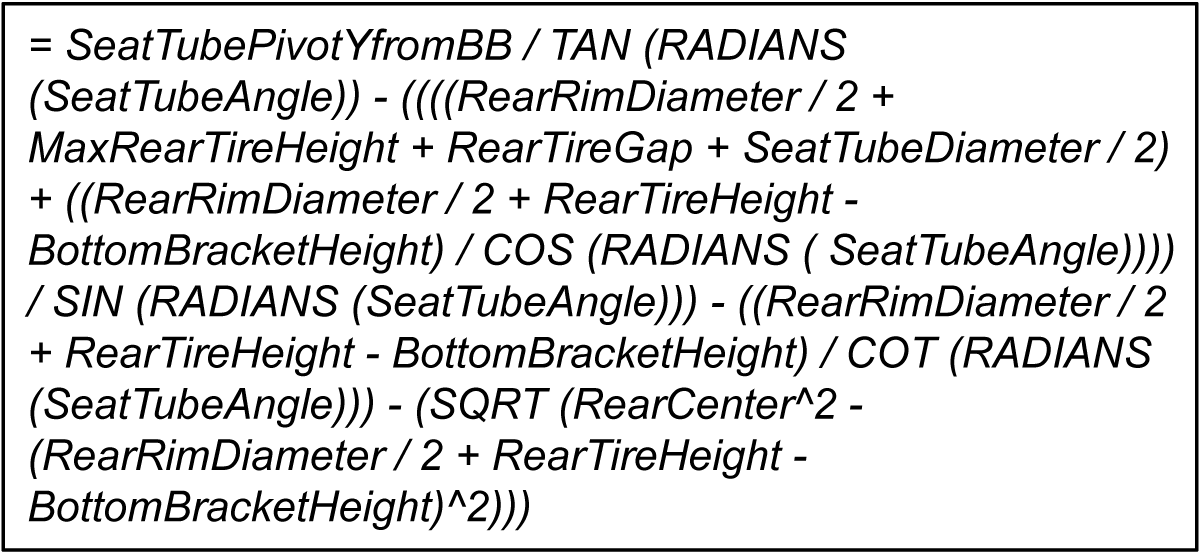
This is the current (2024) easy calculator that is used for setting the fixture:
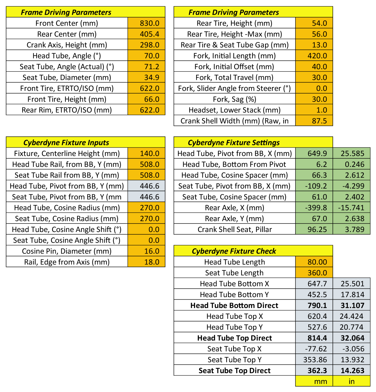
Of course, I have all of this automated inside my modeling program to ensure that the development of the fixture would move at a rapid pace and I could check against actual bikes in a virtual environment.
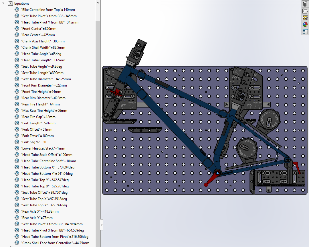
Notice that all of the calculations from the Excel sheet have the same value as those in the solid model. The math is all good and validated in several scenarios. Once you develop good math, it has immense downstream value.
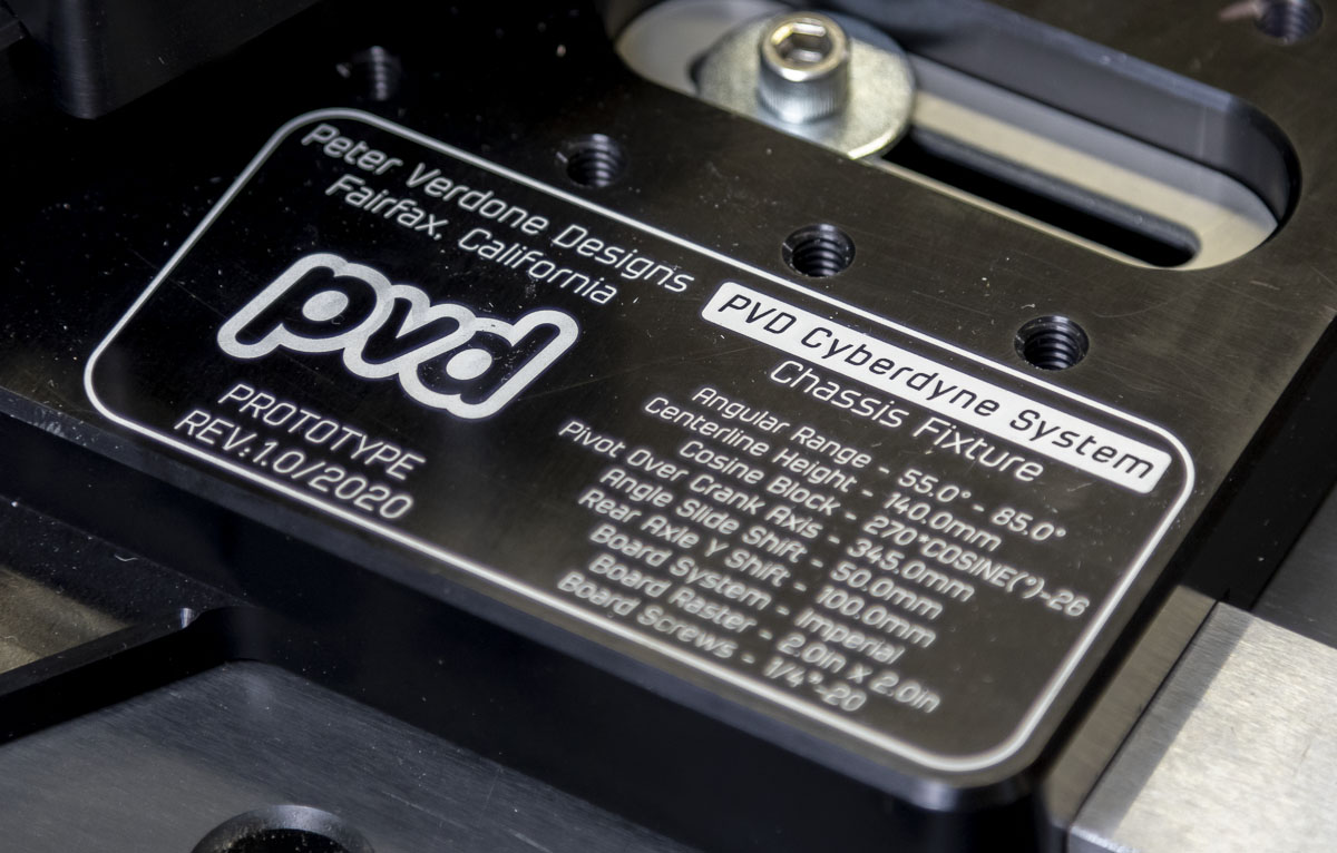
This spreadsheet gives me all of the settings for the fixture. Note, that adjustments can be made to the fixture plate locations on the raster and accounted for here, but pivot heights of 345mm really will account for almost all reasonable designs with the tooling as it stands. This also ensures that the angle plate isn’t hanging off the table. Situations will come up for adventurous designers that require different setups and moving the rails up or down two or four inches can be adjusted in the spreadsheet.
A 55 to 85 degree angular range for both the head and seat tubes without limitation on lateral shift allows for countless designs and far more range than any other fixture that I know. Modern dirt bicycles have head tube angles in the 67 to 64 degrees range and actual seat tube angles just under 70 degrees. I don’t know where all of this will end up but I know that I’m ready for it.

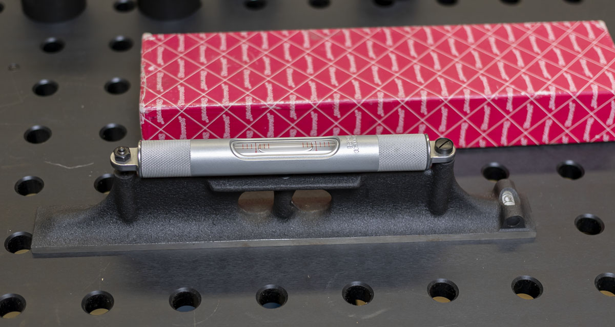
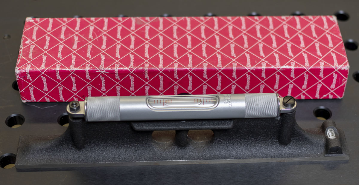
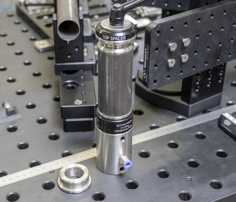
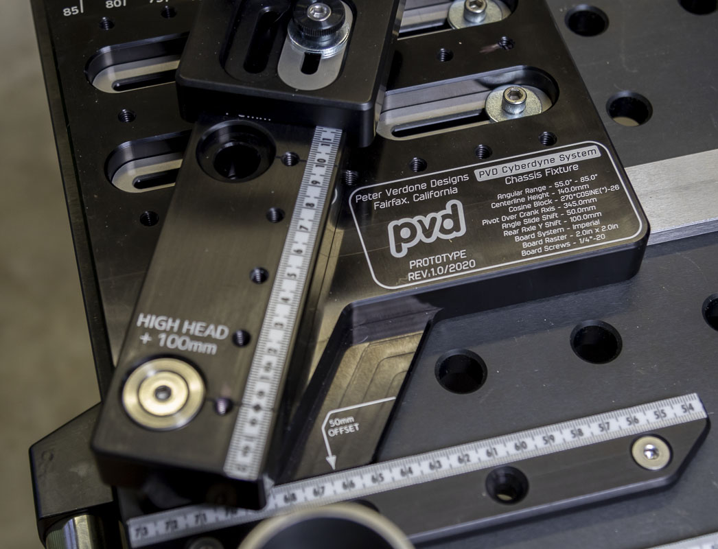
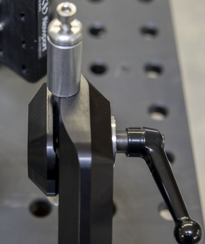
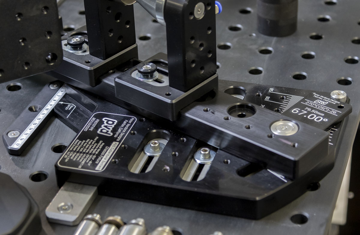
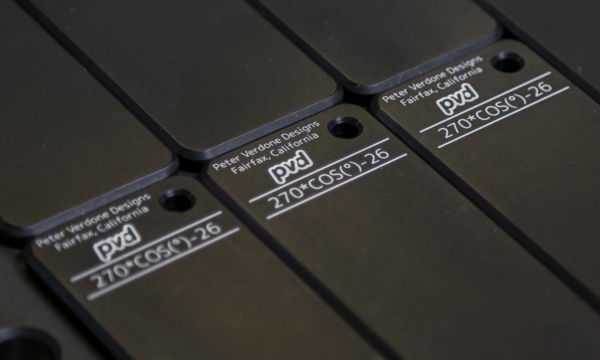
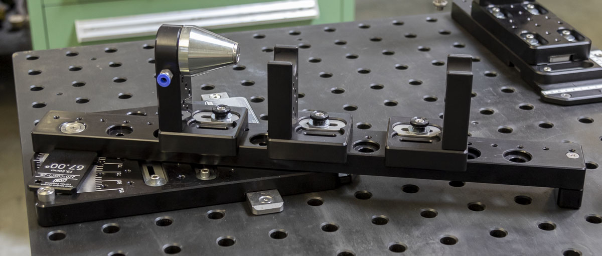
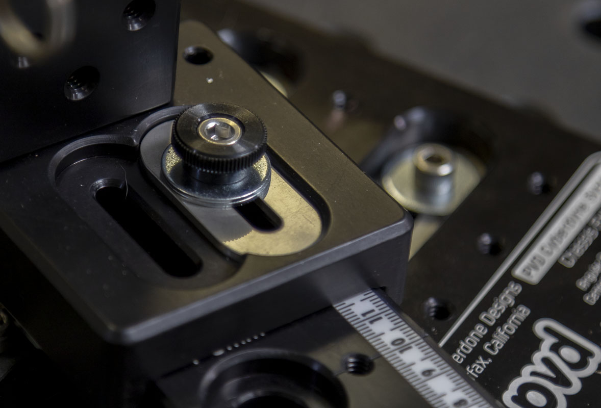
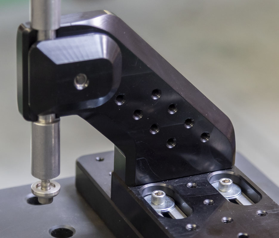
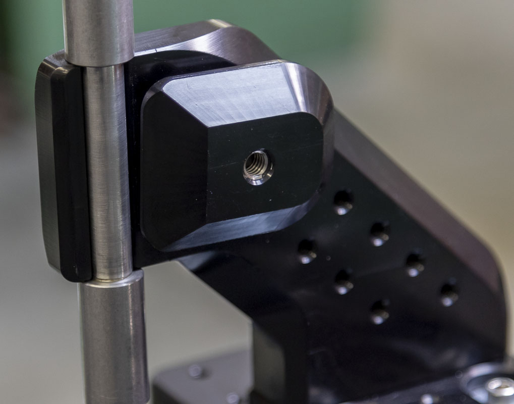
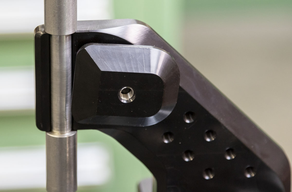
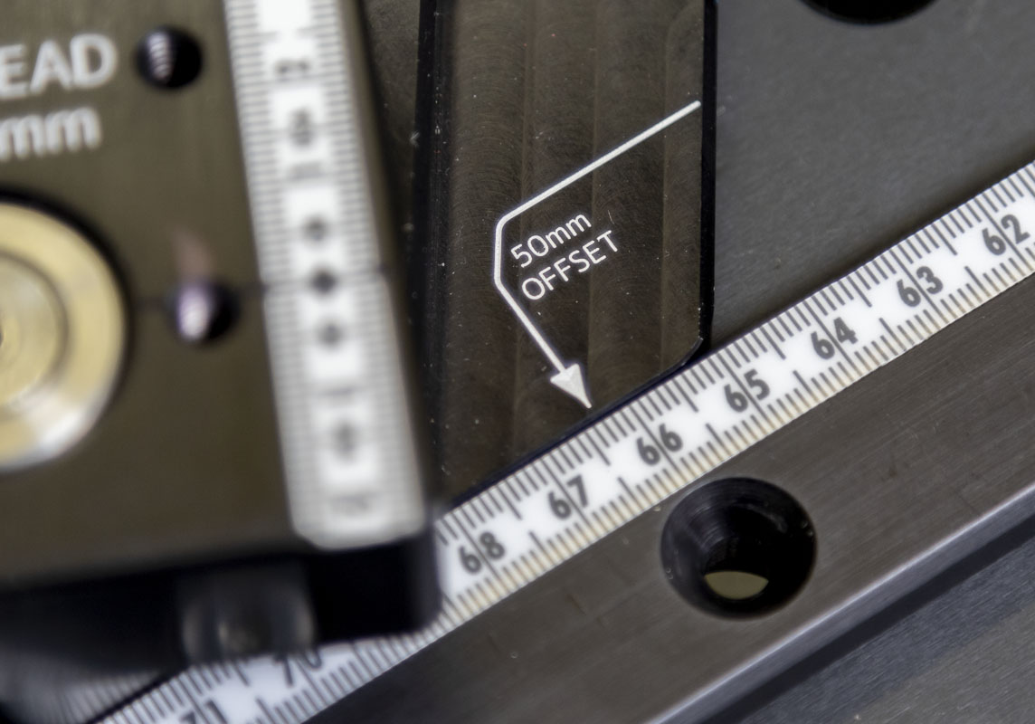
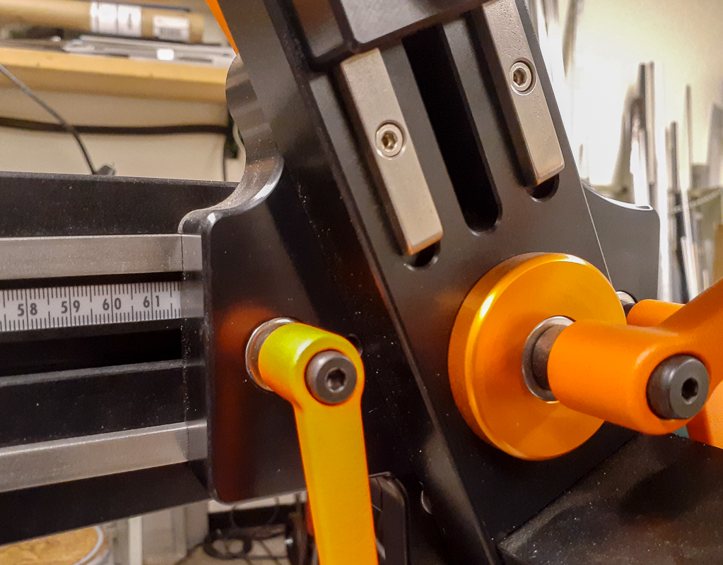
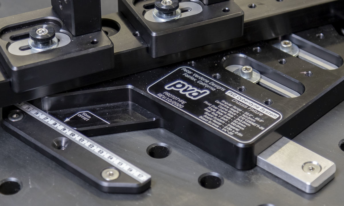
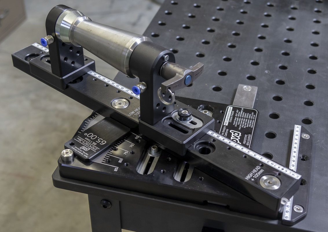
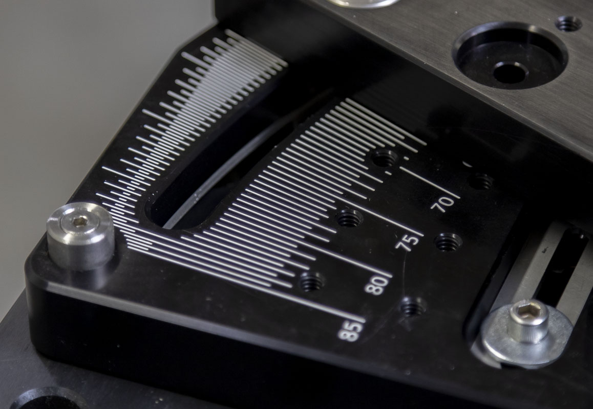
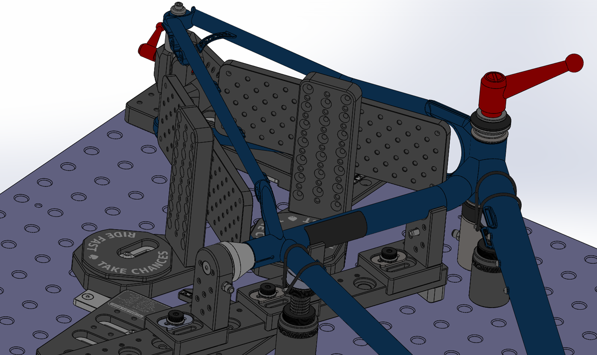
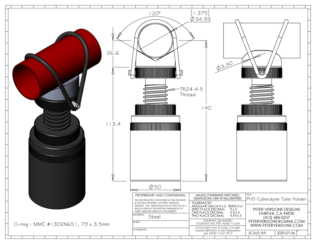
Note here, the introduction of the Cyberdyne cosine bar angle adjustment. One of the things that I hated doing on the Anvil fixture (and is similar on other fixtures) was getting the angular location of the head and seat tube set precisely. I was forced to use a digital protractor and it also involved a lot of fiddling. In the end, I always worried whether it was true to the print. I want a fixture that makes it easy to work with frame angles that are under 0.10 degree increments and repeatable and normally that isn’t easy. So I built a 270mm cosine bar into the angle plates. Now, I can cut a coupon to the right size for a specific angle. That would be the length of the bar (270mm) multiplied cosine of the angle (less 26mm). This produces an exact and repeatable angle, every time. Even better, since the head and seat angle plate are the same parts, an angle coupon will work in either tube location. In time, common angles will be on hand, like 65 degree, and setting angles will be a quick, precise, and foolproof step.
The formula for the angle plate and it’s length is laser etched on the cupons and the angle plate for error checking and ease of reproduction. The angle plate also has other important fixture information on it for quick reference in the shop.
I really love the cosine bar angle adjustment system on this fixture. Aside from how simple it makes the fixture to set, it’s because it is in the proper orientation of a definitional cosine. I bust a lot of balls on folks that can’t point out the cosine for a point on an arc. I’ve talked with physics professors, mathematics professors, master’s candidates, students. Not one to date has been able to do it and are even confused when it’s explained to them. Here, I do it right, use it right, and call it right. Ya gotta love this game!
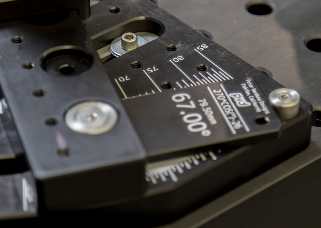
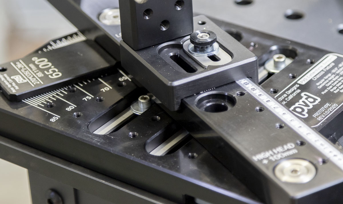
In addition to the cosine bar adjustment, the fixture has laser engraved angular registrations down to 0.25 degrees for quick reference and error checking of the fixture setting at the point of sale.
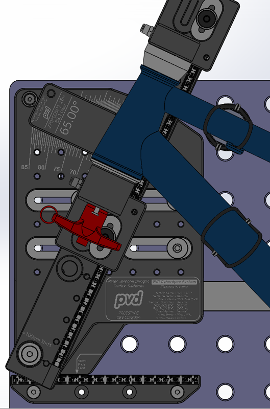
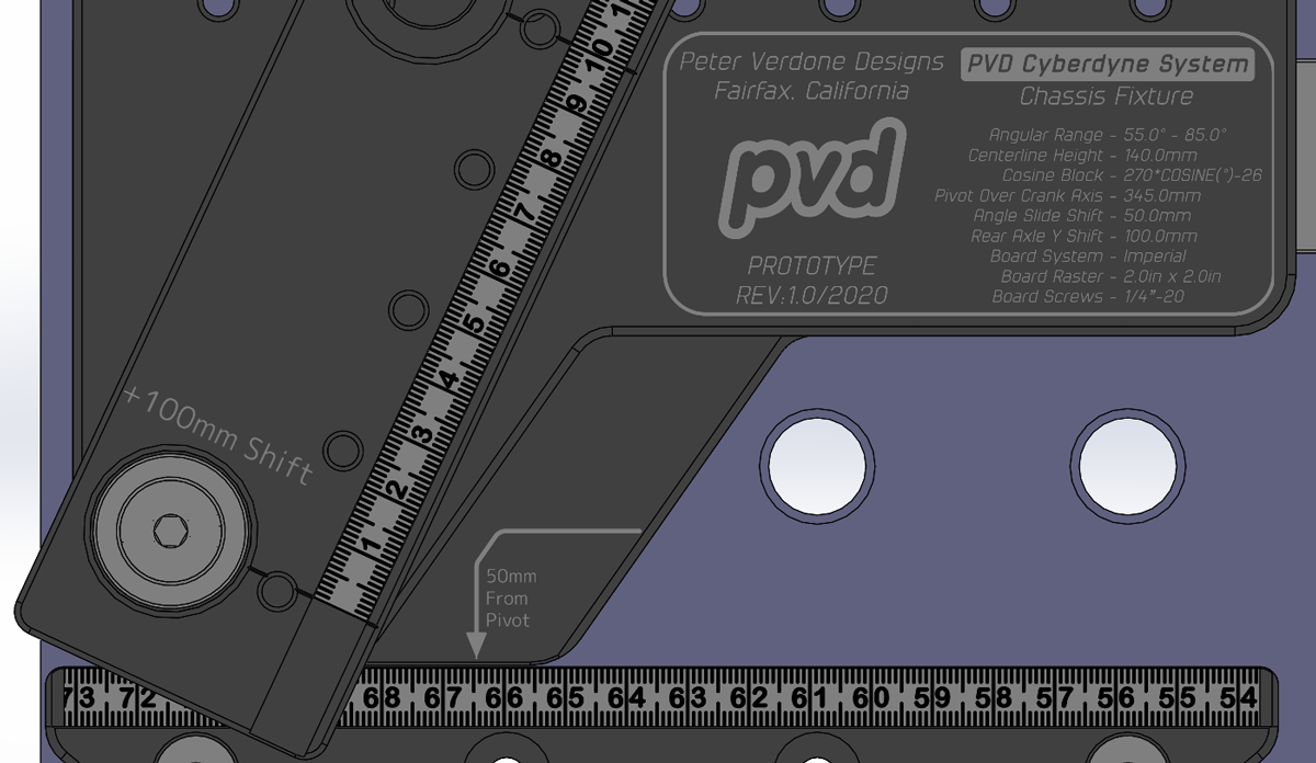
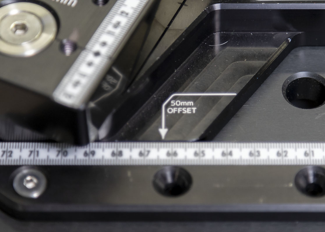
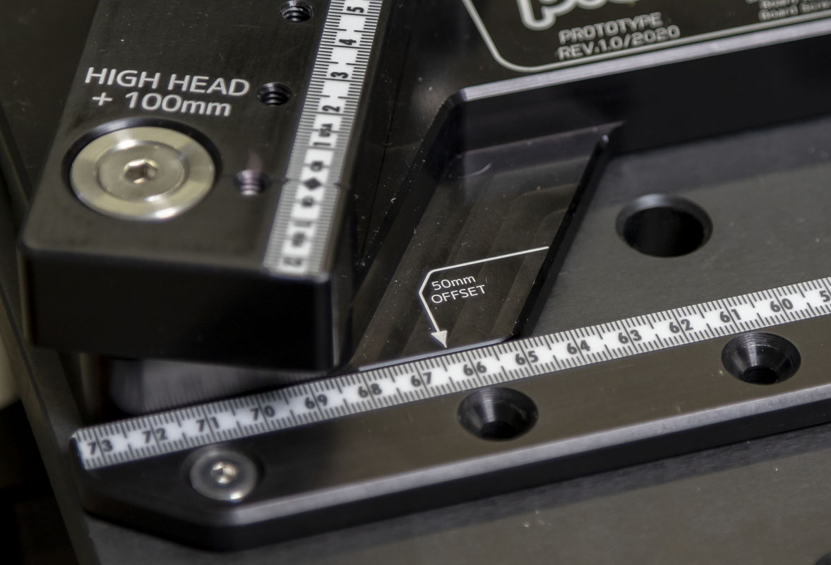
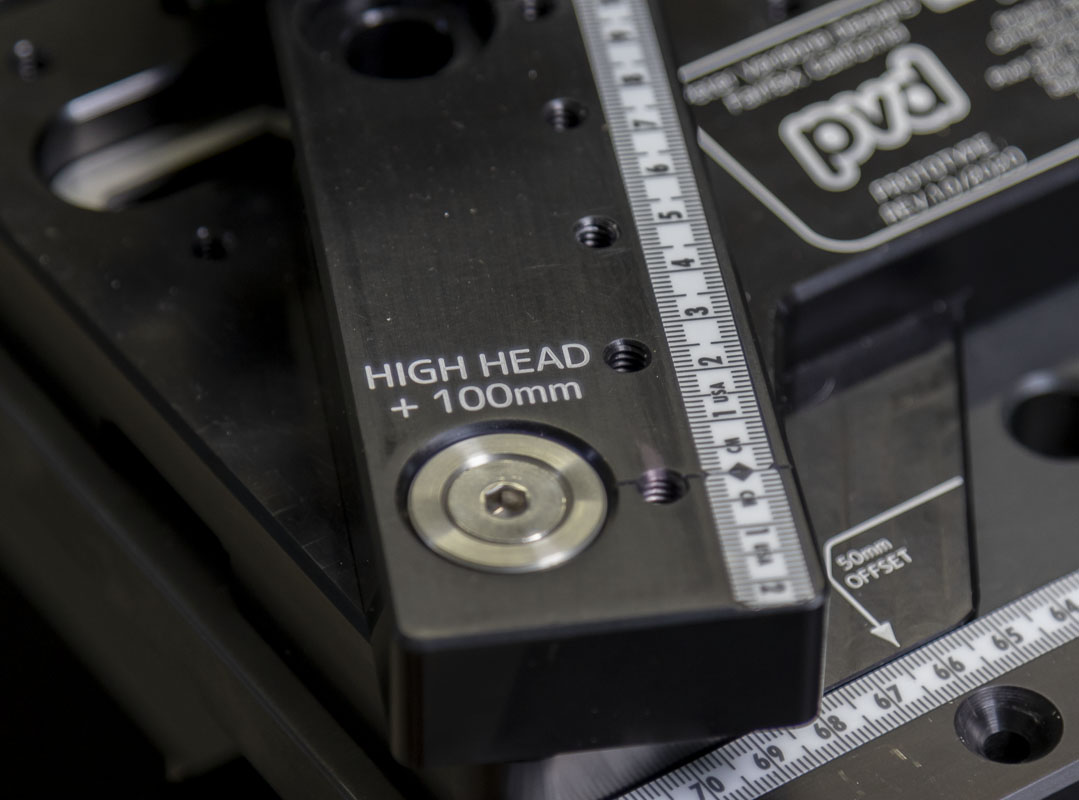
The head tube beam has three different positions to an extra 200mm of range for both high and low head tube heights. Simply unbolt the beam, move to the new pivot, and remember to add or subtract 100mm from the registration. This keeps the footprint of the tool down to a minimum but makes an insane range of bikes possible, from the tiniest of push bikes to the heights of a 36er.
That pivot shift is also in place for the seat tube beam but for different reasons. While care was made in designing this fixture to keep tooling away from the crank axis, when that space isn’t needed, it can be better used to support the seat tube. The beam can move very close to the axis when that is favorable. When pivots and segmented regions are being added, the beam can be moved well away from the axis. There are five pivot locations over a 200mm range.
For either the head or the seat angle plates, if a bike is outside the normal range, the plate can simply be moved up a few pin locations with a corresponding adjustment in the spreadsheet. Super tall and super small bikes are very easy here.
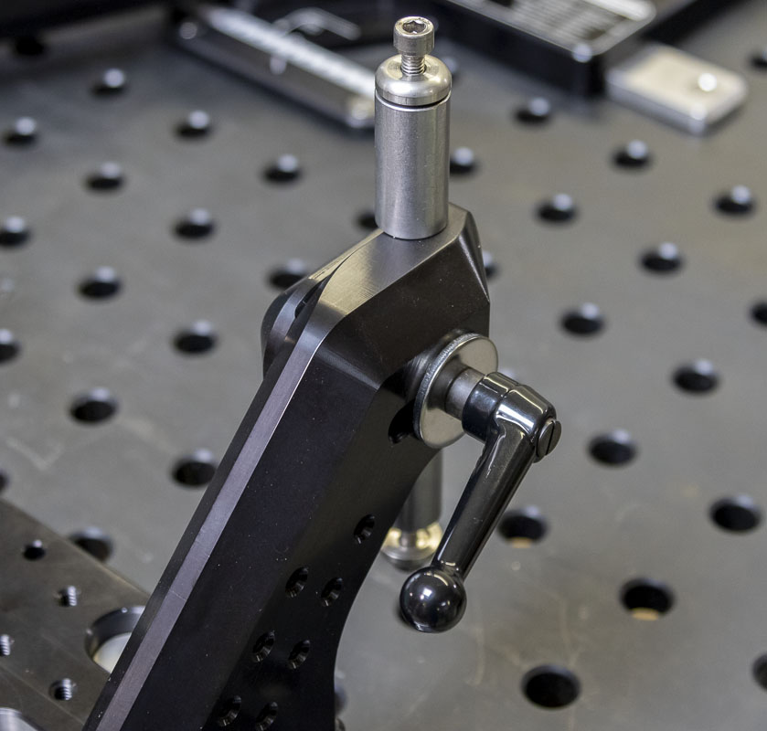
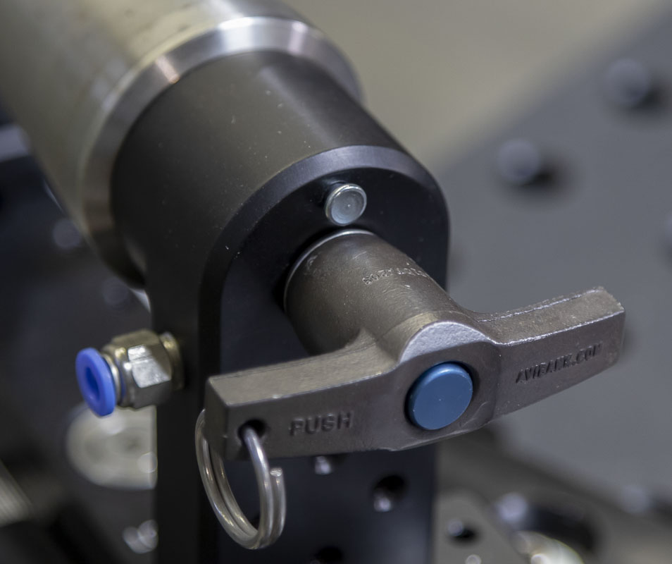
One of the big differences in the Sputnik fixture compared to the Anvil fixture is the ease of removing the tacked frame. The Sputnik is awesome. A quick lever pull and a couple of screws and the bike comes out without disrupting the critical fixture settings or much else. The Anvil was terrible for this, requiring a total loss of the head puck placement. The rage of doing this is real and the action of the axii far from smooth. I wanted the functionality of the Sputnik fixture but was certain that there was a simpler and more robust way of doing it. On the Cyberdyne System, You pull the two pins at the head, either to the stop or all the way out, slide the seat tube cone away, loosen the crank axis and dummy axle screw, and slide the Chainstay-X back slightly. The bike slides free easily. The only thing that needs resetting is the Chainstay-X for a replicant to be produced.

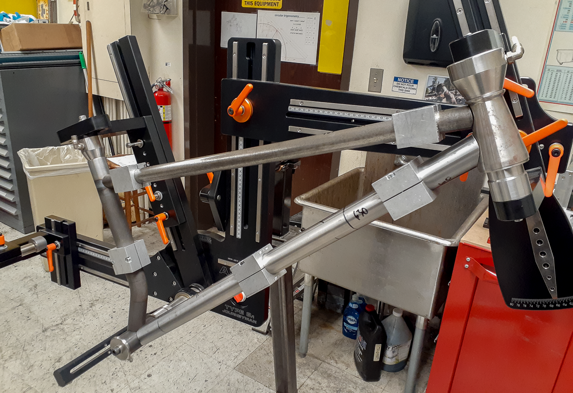
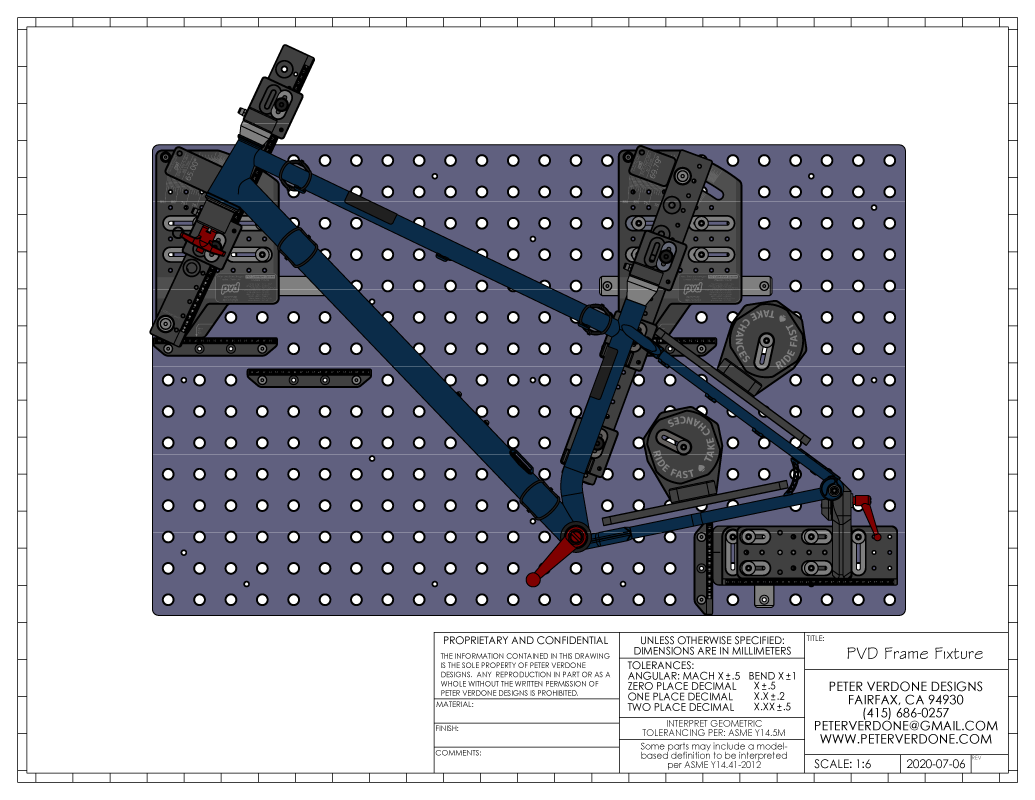
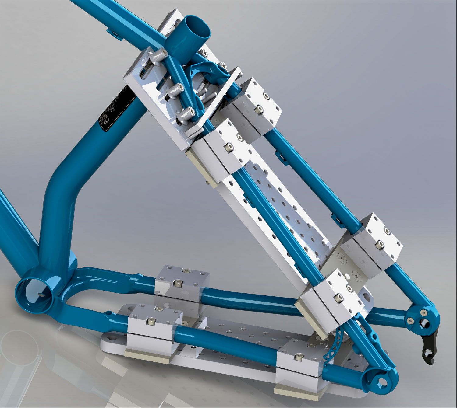
The frame is oriented over the surface with the drive side down. It doesn’t really matter which side is up or down from most perspectives but I made this choice for an important reason. At the very rear of the chassis, we need to do two things while making the bike, clock the hanger and attach brake mounts. Clocking the hanger isn’t that difficult to do and is made easier by being close to the surface of the table. Mounting brake bosses is a huge pain in the ass. I wanted to make that as easy as possible to work around and keeping it up and clear would do that. Now the builder has all the room in the world to mess with caliper mounts and modifications on the table.
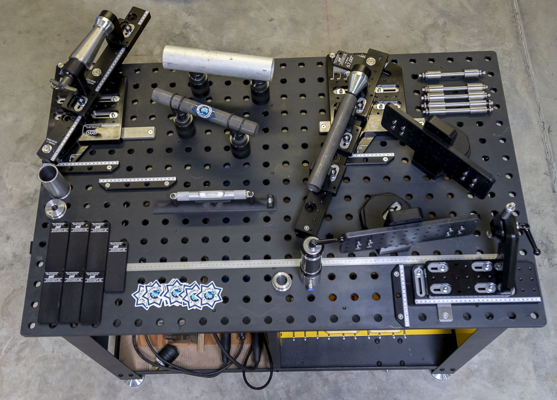
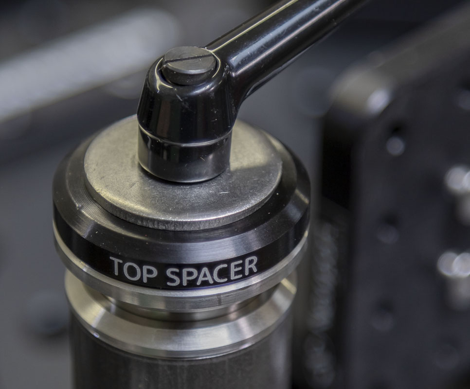
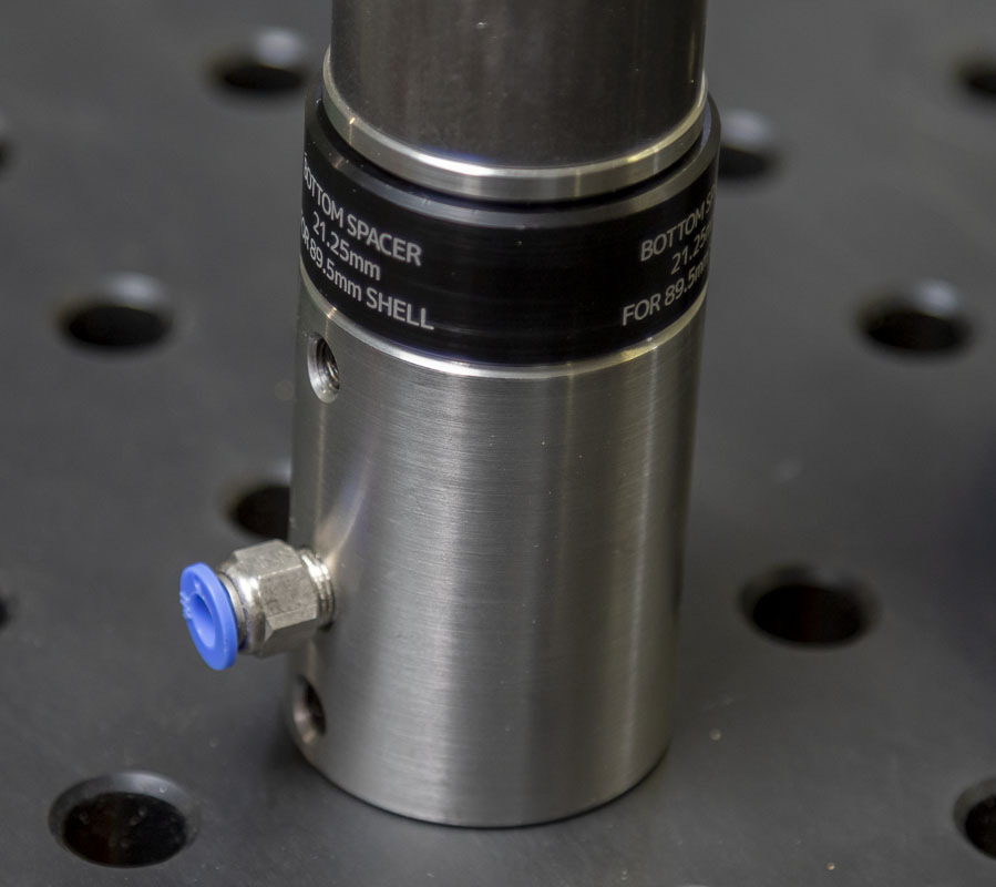
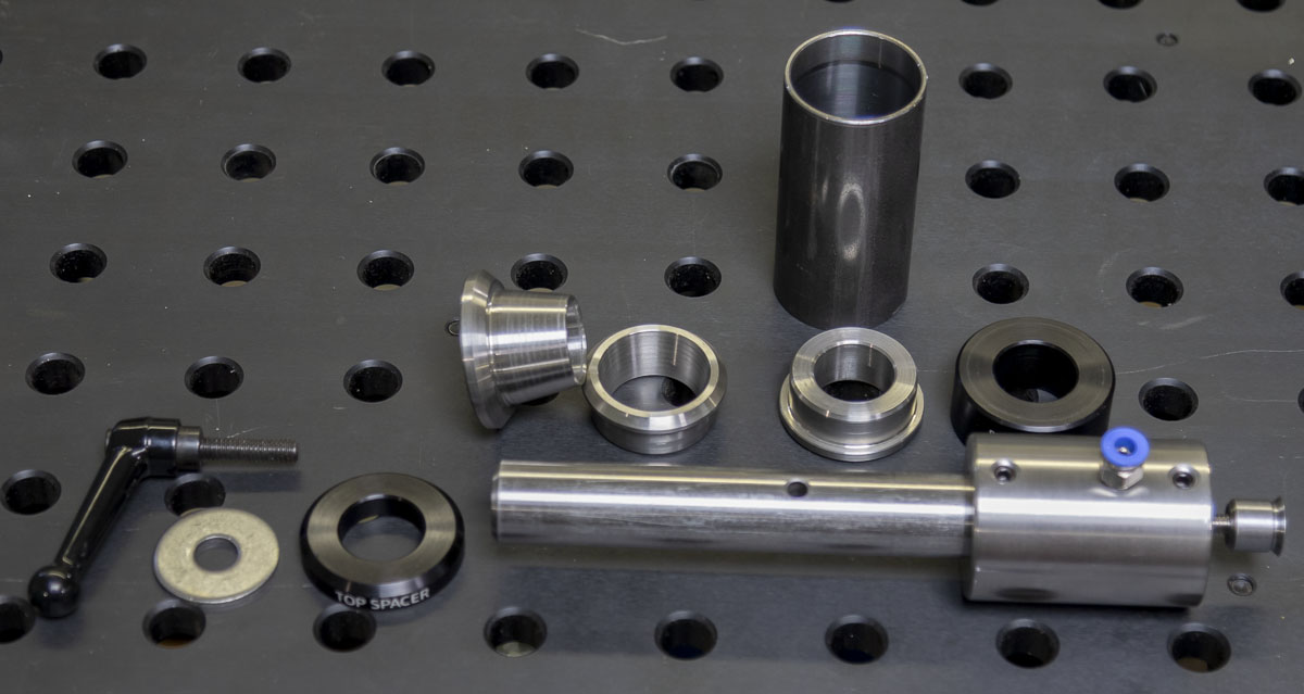
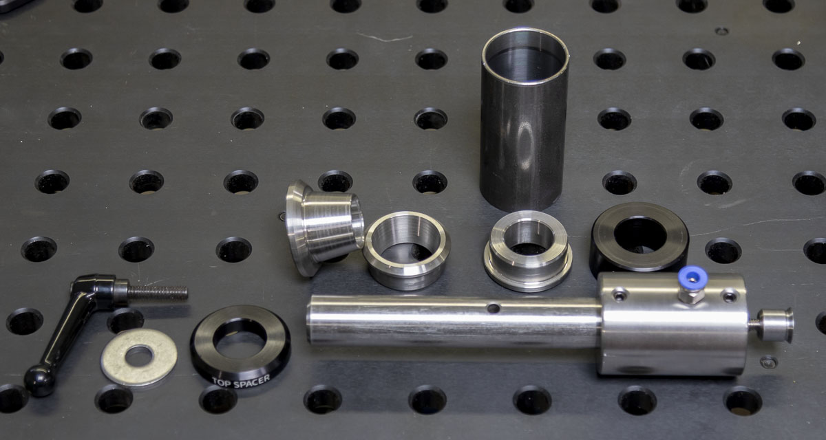
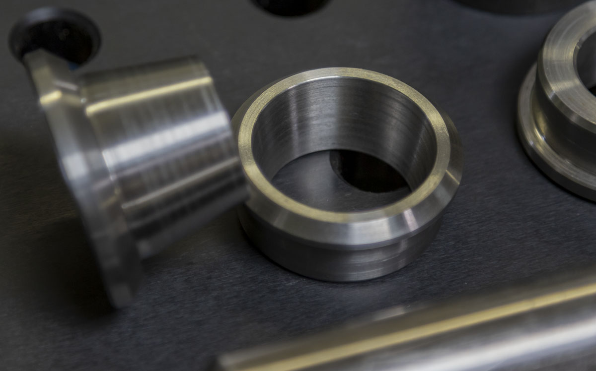
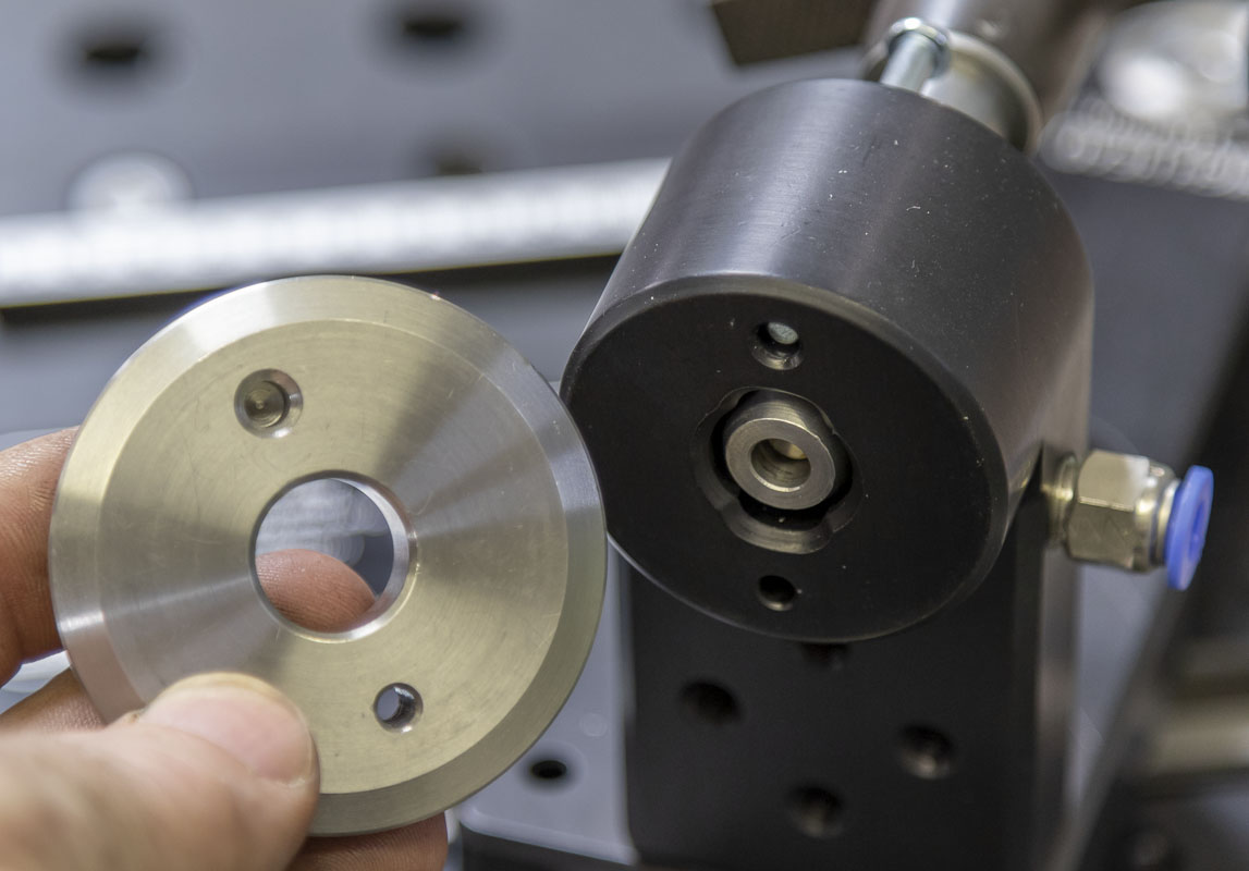
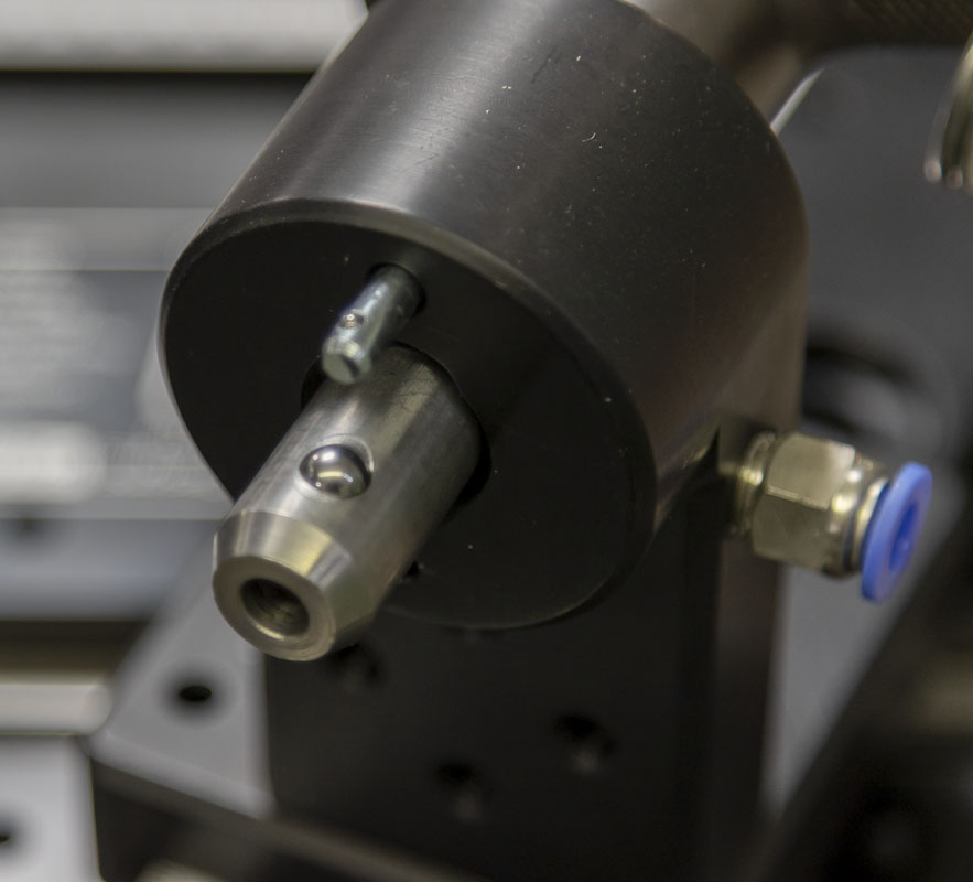
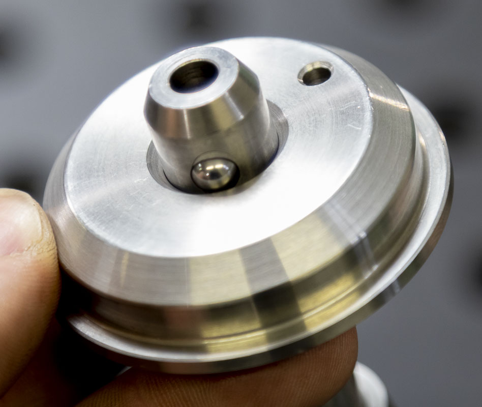
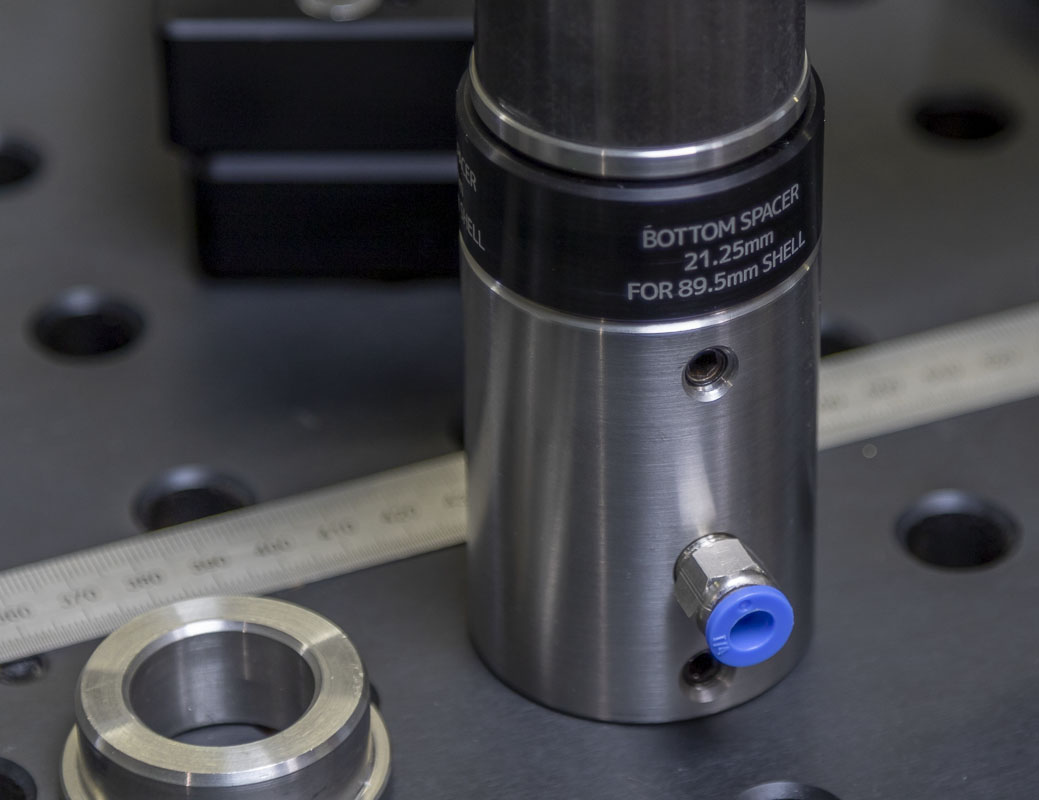
I don’t like that other fixture designs don’t support both sides of the crank axis rigidly. They will offer good support for one side of the shell but the other is often floating at the end of a bolt. This relies on the structure of the shell for axial alignment during the welding. I use very light, thin walled shells that are almost cut in half under the tubes for cable routing. I always noticed how much the bolt mount would loosen after heavy tacking. This, because of heat distortion. On the Cyberdyne System, I support both sides of the shell over a 1″ diameter ground stainless steel shaft set deep into the table spacer. The reducers fit the shaft very closely to support the alignment of both sides of the shell as rigidly as possible. One side of the shell is not more important than the other, they are both important and I treat them as such.
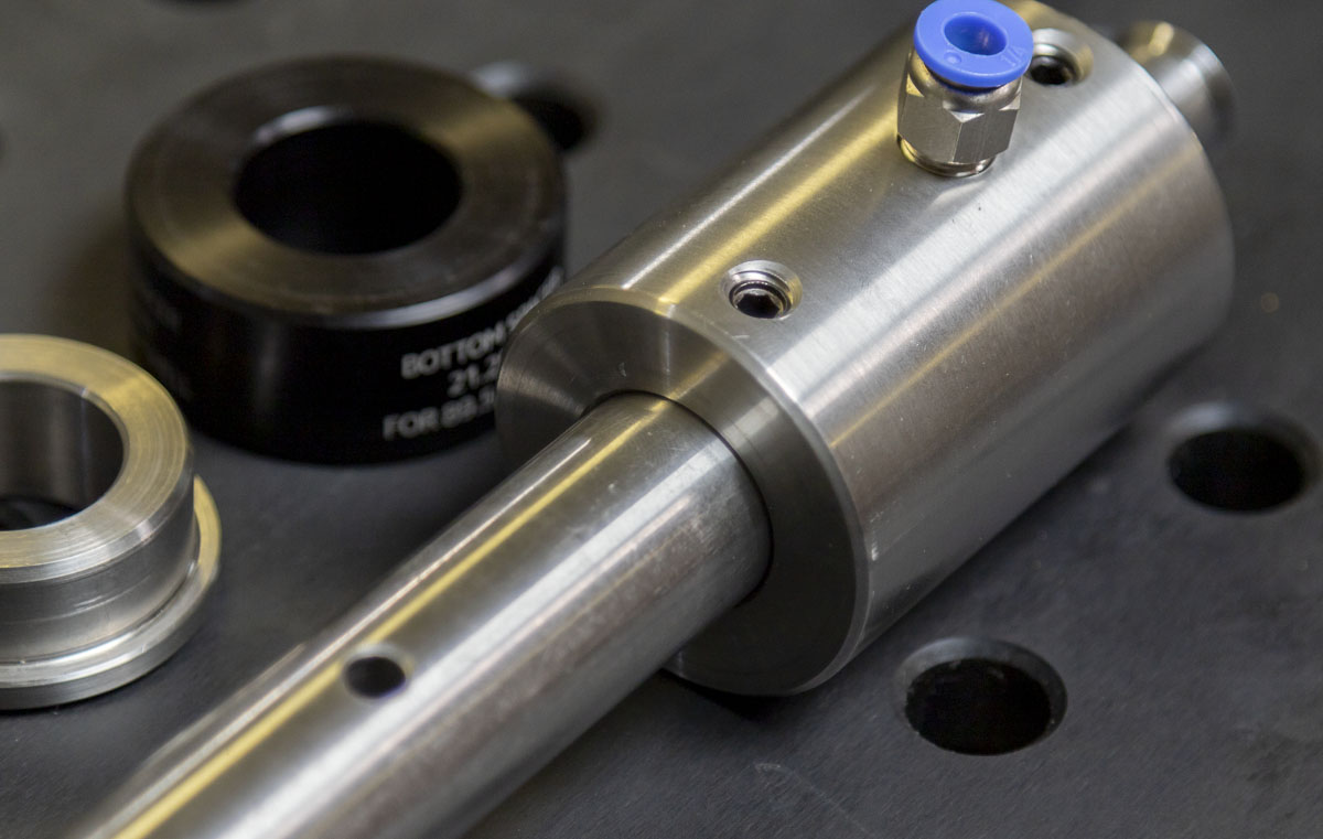
Spacers and reducers can be cut for any common shell diameter and width. The widest of fat bikes aren’t a problem at all.
Because of the close tolerances that I’m using in this setup, to ensure that the frame doesn’t get stuck on the crank axis pillar after welding distortion sets in, I designed a split taper reducer that requires only a small amount of shift to fully release from the pillar. The geometry has been optimized to get a drift and hammer into position if absolutely necessary. Nobody likes a stuck frame.
I was talking with Austin about this setup just before taking all my photos here and he made the suggestion of integrating small jack screws into the split taper reducer instead of access for a drift. This was instantly obvious and better and will be integrated into future versions. Probably along the lines of 3 #6 set screws at 120 degrees apart. This was a great idea but just a little late for the first prototype.
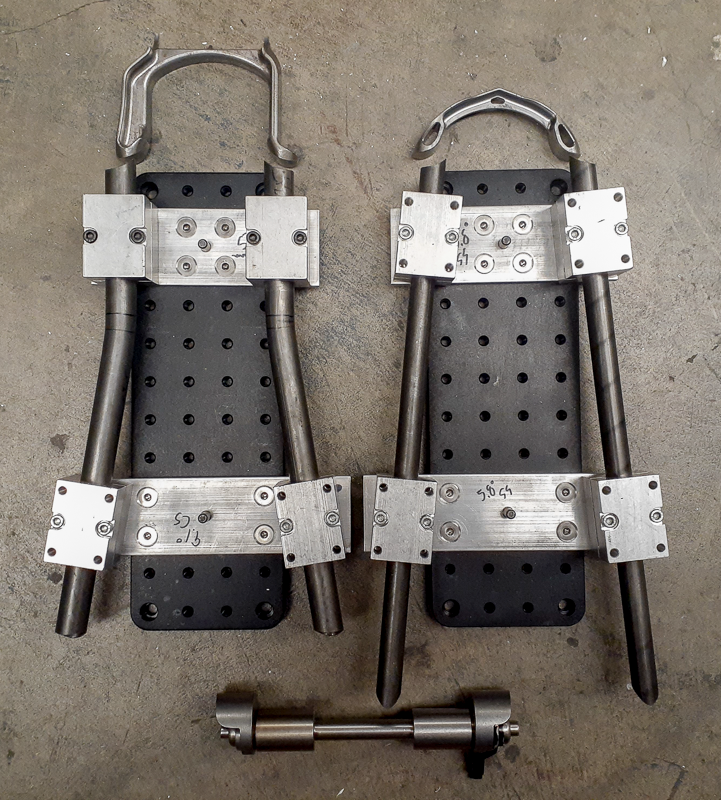
Given all of the segmented chain and seat stays in my designs and that almost everything I do is using a yoke or asymmetric disc mount cut, I designed some auxiliary towers to mount breadboard that will allow fixturing of these parts on the centerline and in the correct position. These sit on a special cam plate that allows any position over the 2″ table raster. This is a clumsy design but at the 2″ raster scale, it’s what I had to do. A 1″ raster would have been significantly less awkward.
I’ve already been using this type of construction of using the stays on the breadboard but now I can ensure that it is on the center-plane and square to it.
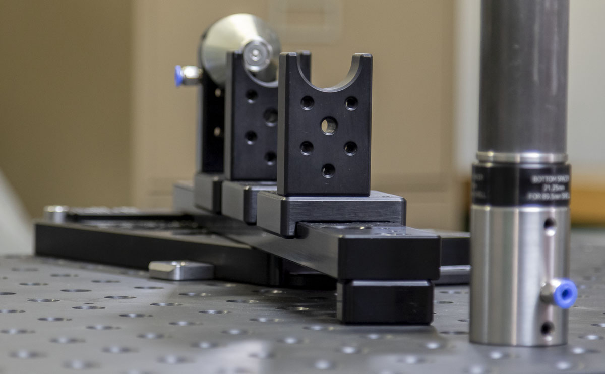
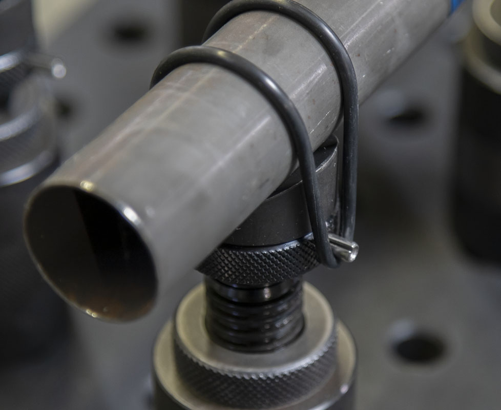
Mid-span tube supports are on locking heavy steel screw jacks, 120 degree vee blocks, and can be set to any reasonable height and tube diameter (5/16″ to 2 7/8″). The tube is secured by an o-ring or rubber bands over pins. The calculation spreadsheet even has the setting for the jack height calculated for a given tube diameter and center-plane height. The mass and substance of these jacks means that they hold the tube without tipping easily or needing to be fixed.
To protect the tool and keep it running smooth, I had some slotted and arc washers waterjet cut from 0.090″ stainless steel for all of the dynamic clamping points. This should prevent the screws from augering out familiar patterns that make it hard to set small deviations as the tool ages.
Notice, most of the free space on the fixture components have auxiliary 1/4-20 rasters sensibly located on them to make future uses or method testing very easy to design and implement to an already existing mount. I can’t know the future or what I’ll need to do but I want to have this tool ready for any idea. I’m sure that this will produce gold at some point in the future.
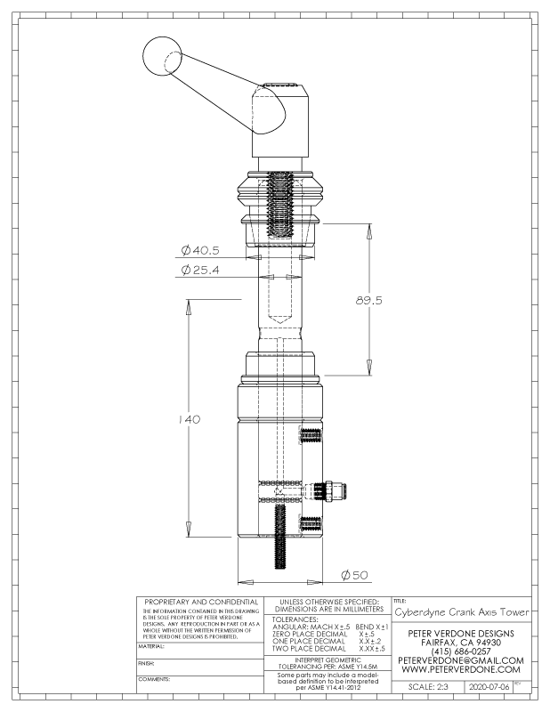
Argon gas plumbing is provided at the top and bottom of the head tube, the top of the seat tube, and the crank axis. I tend to work with steel and don’t purge when I tack but it was the diligent and responsible thing to ensure was in place. I don’t know why but maybe a titanium frame will sit on my table one day.
Early in the design process, I was contemplating the use of cast MIC6 (65HB), Alca5 (70HB), or ATP5 (70 HB) plate for my parts. These materials are often used in tools because of their thermal stability. Once I found ways of reducing the scale of the plates to handy sizes, I decided that anodized AL6061 (95HB) would be a better option thanks to the increased hardness of the material. The cast plate is much softer than the 6061 and that resistance to wear and denting would be more important than the thermal stability of the cast material. The added ease of reduced shipping costs and availability of the AL6061 didn’t go unnoticed. Every now and then, the most convenient material can be the better material.
Since this was such a big and complex project and the financial investment so great, I chose to have a few engineering design review meetings with a few of my mechanical engineer and machinist friends via Zoom. They were ruthless. I came away with piles of notes that improved the design and pushed me to solve hard problems in advance of them becoming apparent during production. Pride is a deadly sin and I’ve seen too many people put a lot of time and money into projects that a basic design review could have rescued in advance. I didn’t want to be that guy.
The COVID-19 problem really got in the way of production. I was able to do a bit of manual machining at my work shop before I was fully locked out of campus. Another friend that was going to do the CNC work lost his access (and his job) when his employer permanently closed the whole division. So many of the situations that I’ve grown accustomed to got blocked. Even with the design fully sorted in the computer, another PVD production run was looking dark, but productive people will always be busy and those that make things happen are hard to stop.
I had one last card to play and it was a good one. A friend, Austin Roche, had left W-2 employment last year to start his own CNC shop in Albany, CA (East Bay). I called him up to see if he was working and it turned out that while the rest of the world was frozen in place, Austin was busy as hell. He had become a real hot piece of ass for the local tech development programs. His NDAs run dank and deep. We talked for a bit about what I needed and how I’d pay and that mine would be a low priority job but I was in the queue and moving forward. Slow beats immobile every day of the week.
One of the nice things about going to Austin’s shop is that he’s running one full size 5-axis mill and another big 3-axis mill with 2 more axii on the bed. Even though my parts had been ruthlessly designed for ease of 3-axis production, the 5-axis tooling made some precision possible, at little extra cost, that wasn’t when several 3-axis setups are needed. This is some really good stuff and I’m going to have a lot of fun designing parts knowing that a 5-axis mill will be cutting them. I’ve even got a few trick brake adapters staged behind this fixture that will be amazing due to the 5-axis cutting. Austin’s CNC lathe also made quick work of all of the breadboard plugs for the RhinoCart top that I needed.
I had the confidence that this tool would work and the cost savings of making two sets of parts were significant: Ronen was eager to have a replicant at a low cost and that would amortize some of the initial programing and setup costs in the machine shop. So, I produced enough CNC and waterjet cut parts for 2 fixtures. I just produced the manual machining for one fixture but it really isn’t that much work to finish the second. Ronen can do that now that he owns his own Hardinge lathe (OMFG!!)
I purchased a fiber laser early in this epoch when I knew that I was going to use it for the detailing of the parts. It took me a few weeks of playing with and testing to get to the level of proficiency needed for precision marking registrations. This all came together just as parts came back from anodizing. The process was so stressful. One little mistake and I was going to ‘trash’ expensive parts. I got it done but it was one of the more knuckle-biting jobs I’ve done in the past year.
An engineering note sheet I made at the beginning of this project-
PVD Bicycle/Moped Frame Fabrication Fixture:
Problem:
- My Anvil Journeyman 3.1 was set to its absolute limit constructing my last frame (Spitfire). As an average sized rider, there is no more room for longer bikes for myself or larger riders. The fixture will also have a hard time with very small juvenile bikes.
- Developments in describing bicycle geometry need to be integrated into a fixture design. Almost all framebuilding fixtures are based on long antiquated concepts in bicycle design.
- I require a fixture that will work with elaborate full suspension and moped designs. There are inherent problems prototyping using a limited fixture design. This has held me back on almost every build.
- I need to replace my current tooling but also need to change the role the tool has in the shop. Basically, if I’m tying up money and space, the tool needs to be useful when not building bikes. A generally fixturable fabrication base would be a boon.
Intention:
Produce a frame fixture that is capable of constructing modern bicycle and moped frames outside the range of older designs. A key improvement is a fixtureable plate design that is mounted to Rhino Cart (Siegmund, Imperial) or optical breadboard to facilitate positioning of tubes, pivots, and brackets referencing Cartesian location. Plate will serve as a fabrication platform when not building bicycle frames.
Notes:
- Optical breadboard with 1” x ¼-20 raster is widely available new or as salvage in the USA. In Europe, 25mm x M6 is widely available and is producible with my design with very slight modification. These tables are a common element in research, engineering, and fabrication environments.
- Large and precise welding tables are available in most higher-end fabrication shops. Building on pre-existing tooling makes sense. Many of these tools are on 2” or 50mm raster by Seigmund.
- RhinoCart as a basis provides a 2” x Φ5/8” raster, is made of 16mm steel ground flat and of very high quality (Seigmund). A metric RhinoCart is also available with a 50mm x Φ16mm raster. This is a surface (48”x30”) that is just large enough for this use but not so large that it takes over a shop. It also comes with wheels and leveling feet for mobility and secure level setup. The utility of using this base is the myriad of other fabrication uses in a shop. Thus, money spent here will be returned in all facets of fabrication.
- Larger fixture-able welding tables and optical breadboards (4’x8’ & 5’x10’) allow frames of wild proportions to be produced accurately and repeatable without changes in other tooling.
- Strong Hand Tools FixturePoint table ($360), 36” x 24”, 2” x 2” x 5/8”, Possible to use at considerably less cost but not large enough of a span. Working on finding very low cost options. This may work for children’s bikes or old style road bikes.
- Other fabrication tables produced by BuildPro translate for this use.
- Several of the primary component parts are used more than once within the fixture, making the assembly far more economical to produce by keeping the BOM low.
- Angular positioning range from 50 degrees to 85 degrees allowing for any imaginable scenario. A key part of this fixture is that it allows for design development.
- 270mm cosine bar allows for extremely accurate angular positioning for both head and seat tube beams. Blocks cut can be used in either beam. The difference in length from a 67° block to 67.1° block is 0.43mm (0.017”).
- Unlimited range of seat tube offset adjustment. This is important as many full suspension designs see offsets over 110mm and this is challenging with existing fixture designs.
- Tandem construction is made simple by adding a third angle plate and beam.
- Rear axle plate is reversible and has multiple positions for extra-short and extra-long rear centers.
- Seat tube beam has several alternate placements to clear pivots as needed.
- Head tube beam has three placements for options for juvenile and road frames, average frames, and large trail and downhill frames.
- Current centerline height (140mm) allows for fabrication of widest common fatbike shells and axles but is low to keep rigidity, precision, and economy maximized.
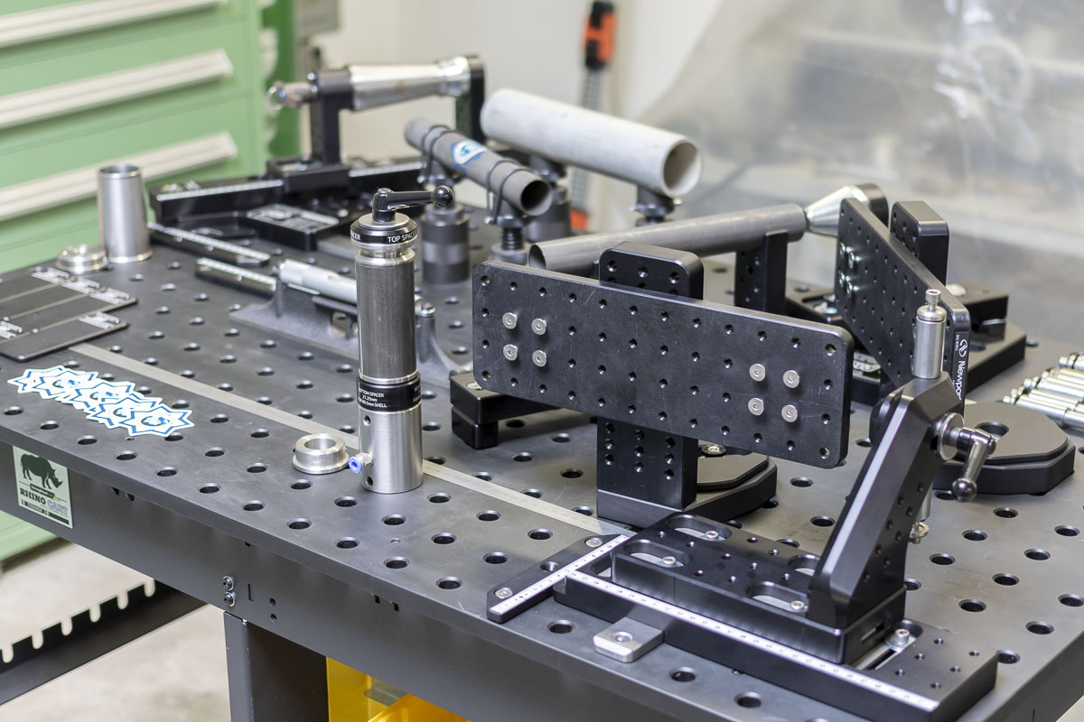
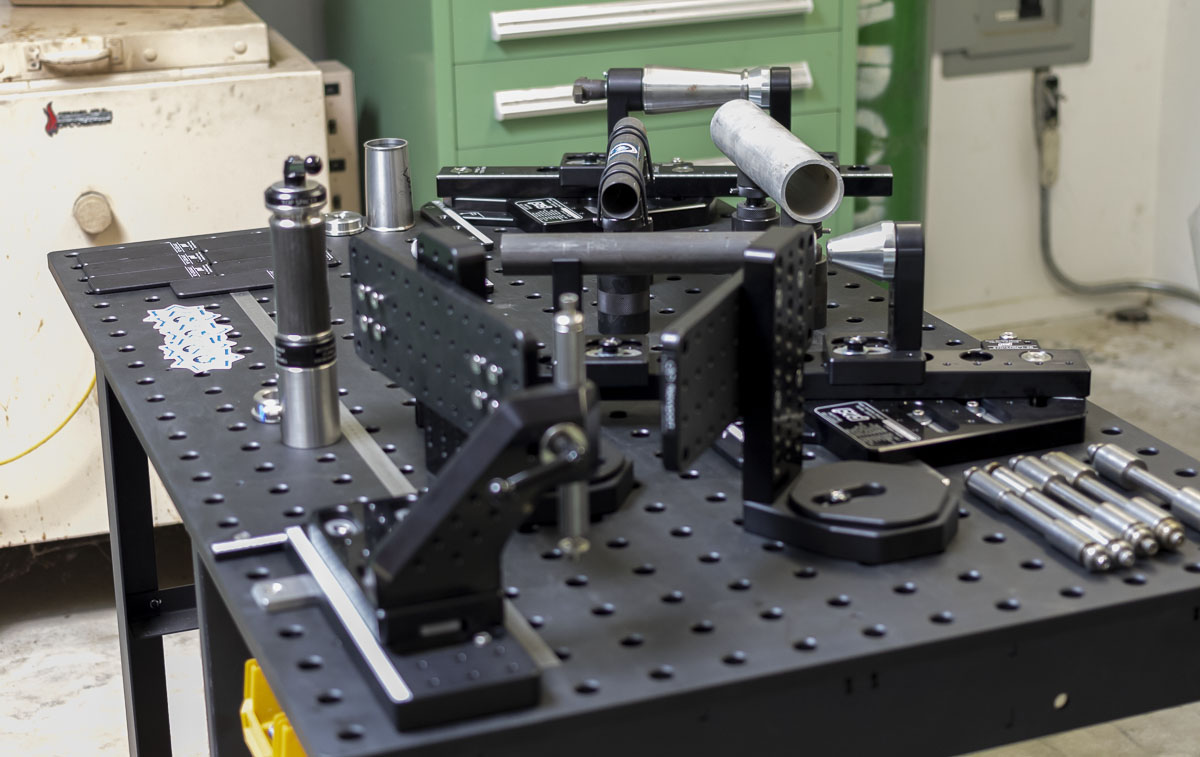
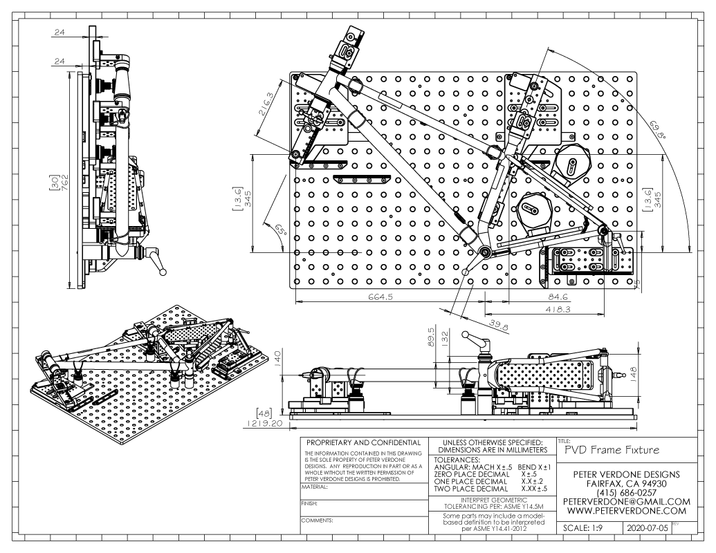
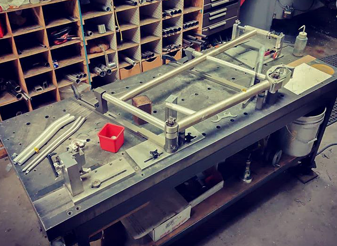
- Frame shown (PVD Warbird) is 850mm front center, 29” wheel, 180mm travel fork and the fixture has significantly more range available. Matrix of past frame design shows scales will work down to juvenile sized frames and traditional road bikes.
- The fixture is used aligned normal to earth. While this is not optimal for high production it is excellent for specials and small runs. The tool could be mounted vertically with a small degradation in utility.
- The component parts of the fixture are significantly reduced in size from previous designs. This makes them far easier to produce economically.
- Almost all parts are designed to be ‘two set-up’ machining and have parallel faces so as to not need special tooling for second operations.
- Beam carts needed to be made for off centerline mounting but they are reversible to keep BOM down and add positioning options.
- Waterjet cut stainless steel slotted washers prevent fixing screws from digging into positions.
- Rigid crank shell mast supports both sides of shell. Other designs don’t take into account shell distortion and keep both bearing bores supported and aligned. This rigid tower does.
- Angle plates have 1” x ¼-20 raster for auxiliary fixturing.
- Quick release pin allows frame removal without change in head tube locator position. Pin can be held in place or fully removed during head tube removal. Pin will be tethered to its associated tooling.
- Crank Axis, Seat Tube, and Head Tube are plumbed for argon supply.
- HHIP 100-140MM ADJUSTABLE SCREW JACK (3901-0079) provides mid tube support for top and down tubes. 16mm modification for standard setup vee pucks.
- Mid-tube support vee jacks accommodate tube diameters of 7mm to 72mm. Larger and smaller diameters are possible by exchanging the 120 degree vee block for a 90 or 150 degree unit.
- BuildPro T54215 V-Block with 120 degree angle used for mid tube support on screw jack.
- BuildPro T54220 Setup cones used on seat tube and head tube top (non-EC49) location.
- Fixture intended as toolroom/prototype grade but should be excellent for light production runs due to extremely stable fixing system. Once fixed, there is very little possibility of movement.
- Large plates of the fixture are below 12”x 10” envelope but are also shaped for efficient waterjet cutting to make better use of material.
- Virtual prototyping shows all scales reading correctly for various frame designs.
- Settings greater than scale range are easily interpolated, but this would be an exceedingly rare occurrence.
- All calculations in spreadsheet and model are based on driving frame parameters and key fixture geometries. Thus, describing the bicycle sets the fixture.
Reference:
- SHT RhinoCart: http://rhino-cart.com/
- SHT FixturePoint: http://stronghandtools.com/stronghandtools/products/welding-tables/fixturepoint/
- BuildPro: http://buildprotables.com/
- Siegmund: https://www.siegmund.com/
- Newport: https://www.newport.com/c/optical-breadboards
- BaseLab Tools: http://www.baselabtools.com/US_c_181.html
- Ebay: https://www.ebay.com/sch/i.html?_nkw=optical+breadboard
- Sputnik Tool: http://www.sputniktool.com/frame-fixture/
- Anvil Bikes: https://www.flickr.com/photos/anvilbikes/
- Benchmark: https://benchmarkjig.weebly.com/benchmark-pro.html
The model is still in detailing. Nothing has been finalized and significant refinements are expected.
This document will be further developed. It was put together quick to explain some expected questions during review.
Nothing gets done in this world alone. Special thanks go out to: Windy Riemer, Austin Roche, Nick Heys, Ronen Sarig, Aaron Spindell, Jeff Buchholz, and of course Don Ferris for the inspiration to work hard and well. I may frustrate my friends to no end but I value everything they do to help me.
BUT IT’S WORTH AGAIN POINTING OUT…
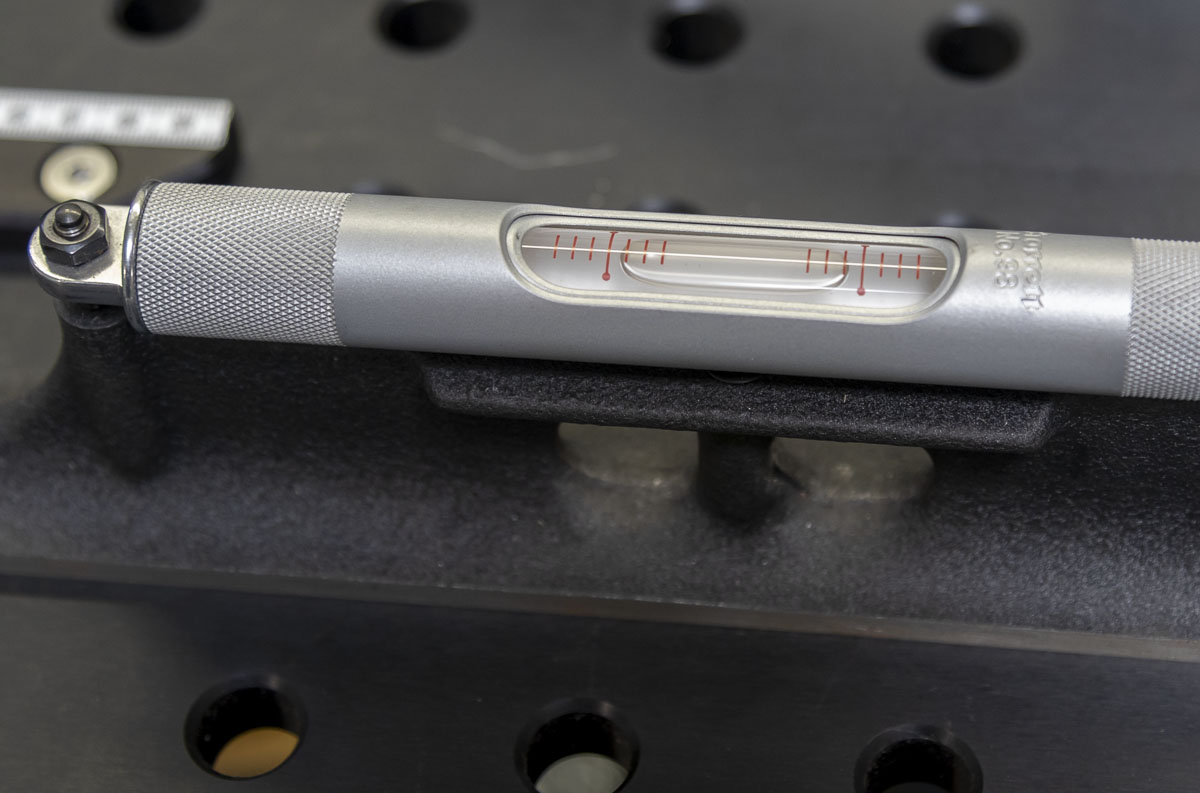
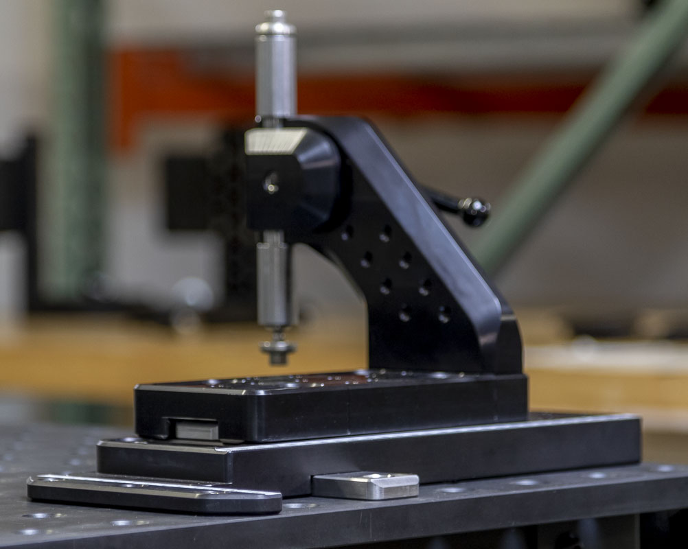
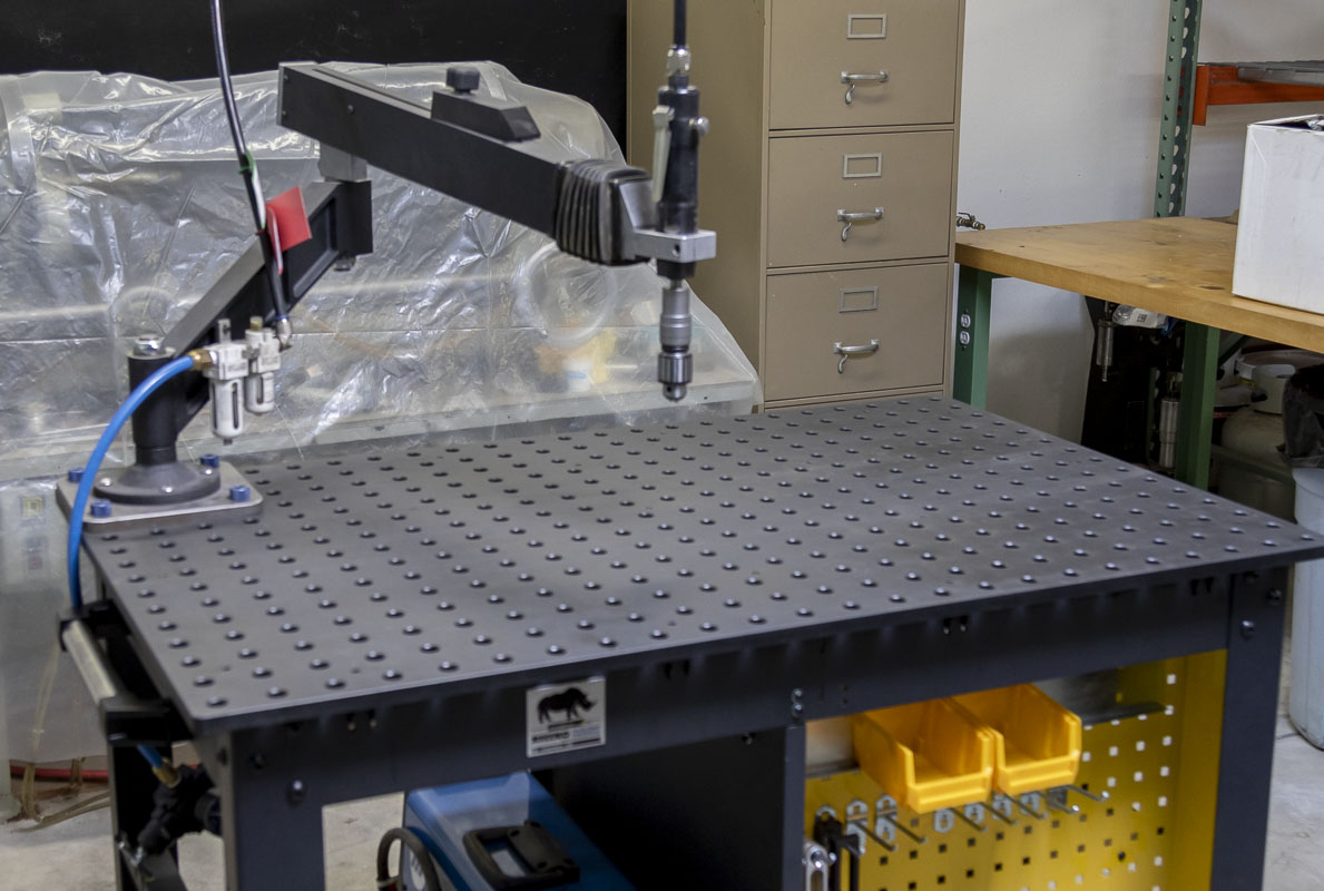
This isn’t just about building the best bikes that I possibly can. It’s also about value and utility in the shop. Besides being an excellent fixturable welding table that can be used for all kinds of fabrication, the RhinoCart has a ton of other uses. From small CNC projects, a machine base of all types, alignment fixturing. Shown here with Ronen’s favorite toy, the FlexArm air tapping tool. This arm can be mounted or removed in about 10 seconds. Other exotic tools can set up the same way. I’m thinking of buying a second RhinoCart and making it into a tube milling machine for bicycles. A modular machine tool with a very low head height that is on wheels would be a great addition to the frame shop!
Here’s another great example of the built in value with this method. Imagine notching a tube, accurately, within a complex welded construction. That’s easy now with the Strong Hands Modular Tube & Pipe NotcherP/N: ATN100
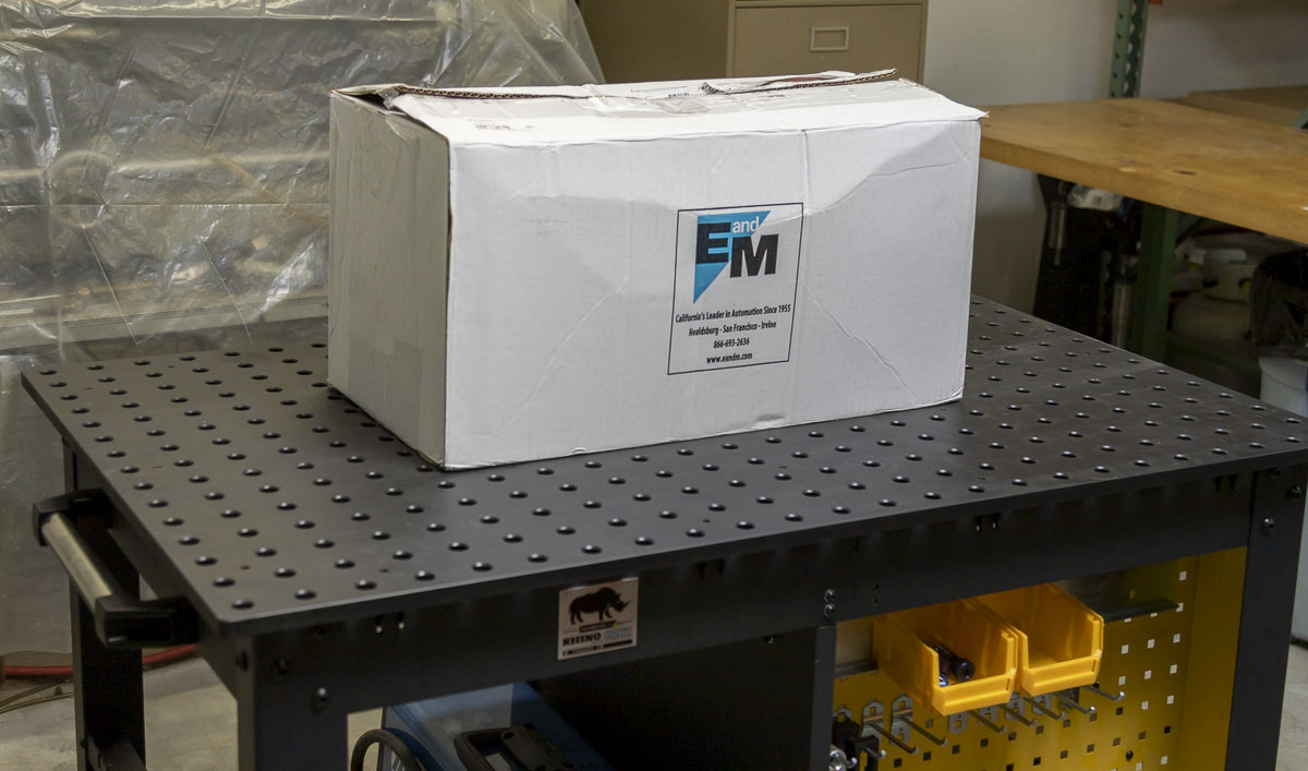
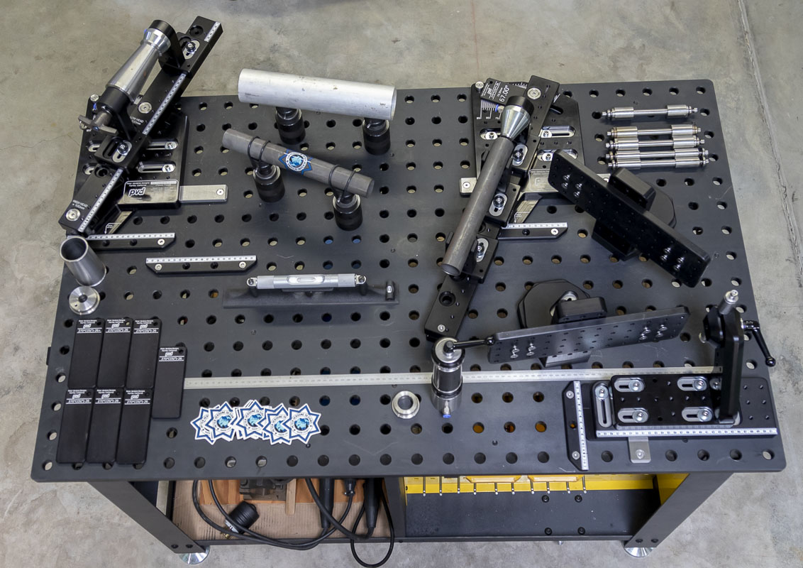
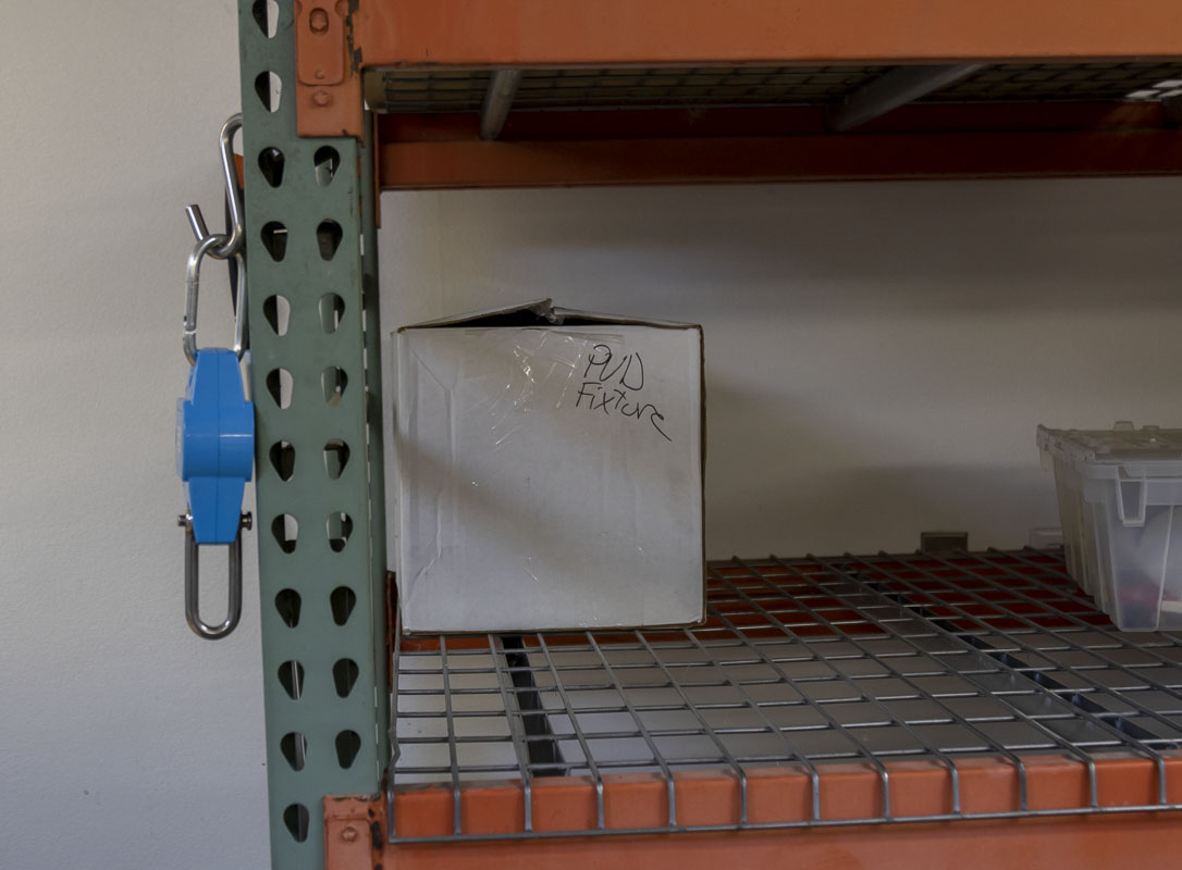
An entire frame fixture and associated tools in a small box. Few fixtures that do so much pack up so small.
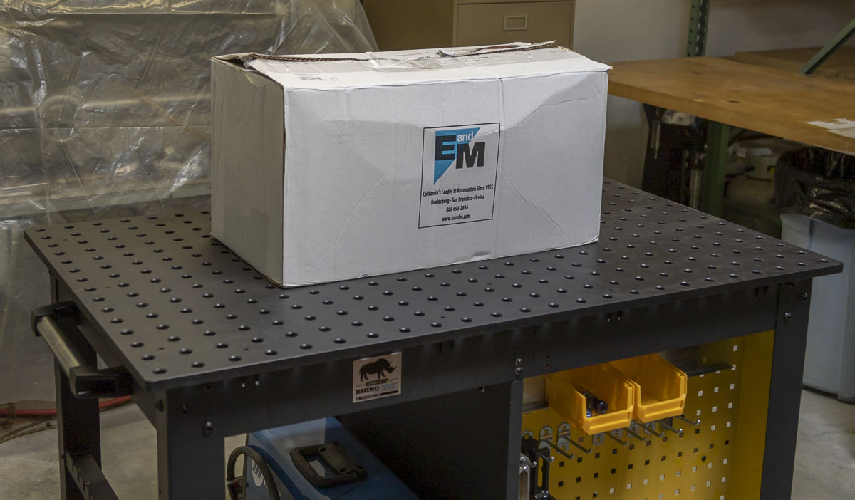
The Cyberdyne System, in a small cardboard box on a shelf in the back corner of the shop. It can be taken out and set up in 15 minutes. Until then, it is safe and out of the way.
2020-08-01 – UPDATE:
In a discussion about my fixture on one of the various message boards, a guy was commenting on tandem folks that use horizontal plate style fixtures. I remembered seeing photos of this type of thing on a friends Instagram so I looked for them to contribute to the discussion.
It was the daVinci fixture. In one of the photos, I saw a small detail that is reminiscent of a primordial vestige of my design. It was a head plate on a horizontal slide. It was archaic and certainly not being used in the way I’m taking the method to. In all my research and work on my fixture, I had not seen anything close to what I was doing until that moment. It’s telling that I arrived at the method from the seat tube rather than the head tube as it is being done by daVinci.
Details that I’ve found out on the work flow at daVinci is that frames are drawn in AutoCAD. The drawings (and fixture) fix the head tube at 73 degrees, It’s not adjustable. Then the head tube is placed measured from a mock front axle location. There are no registrations or references other than that.
I certainly don’t think that I was referring to their work when I made mine but I wanted to give credit where it is due and I hope to find out more to post here.
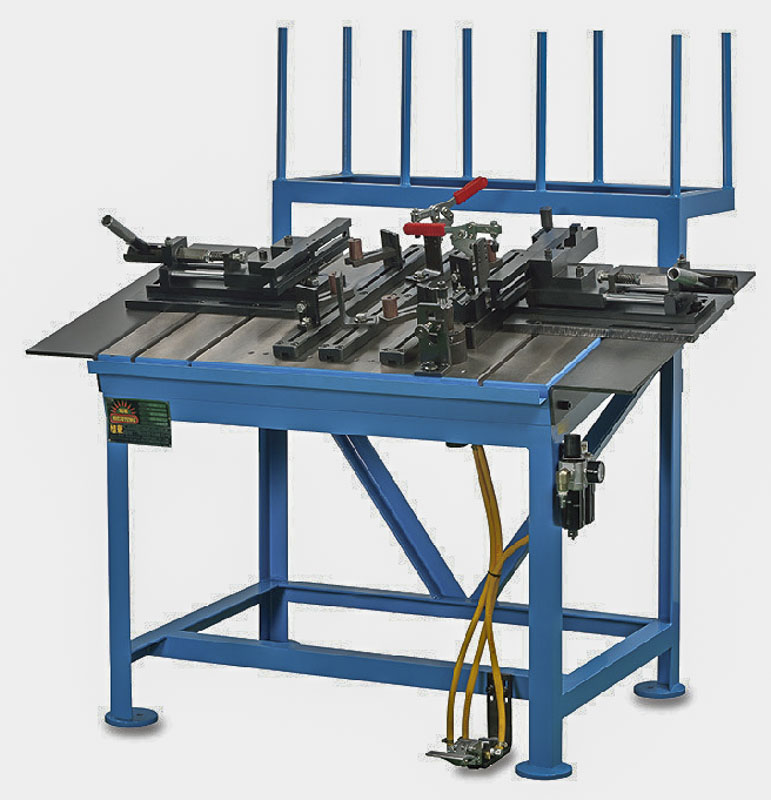
I spoke with Eric Baar about the fixture. He has a fixture in his shop that precedes the daVinci fixture. He got it from Gary Turner (GT Bikes) in Huntington Beach. It’s a high production fixture from Shuz Tung Machinery Industrial Co., Ltd. (Taiwan).
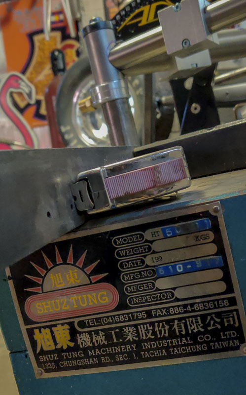
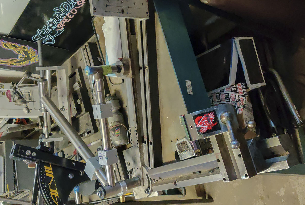
The current version of this tool, the HT-50-116 FRONT TRIANGLE ASSEMBLING M/C (FOR SUSPENSION BIKES) is available.