I started this project about a year ago, almost to the week. It was going to be a big undertaking for me as I haven’t done a lot of this kind of work, or at least properly. I’m happy to learn new things but it can take me a bit of effort and time to wind up for it. It took some time to get back into it.
Last March, just a few weeks into honest efforts on the project and a lot of money spent, I had to drop what I was doing and move to other more pressing matters. I had bikes and parts breaking due to overly thin 3D printing and that needed immediate attention. After making two framesets, a set of skate trucks, a lecture at PBE, and a bunch of infrastructural improvements for making bikes, I was finally able to get back to finishing the CNC ICP/cabinet.
Over the past few weeks, I’ve got the ICP to a good rest point. The ICP works now and can be brought into service with little more work. It’s ready for the next phase for use. I’m going to post here now, even though a few things are left to be done. I’ll pick away at those slowly over time. I need to get on with some other exciting distractions.
I did have to get a little slap dash just to keep project momentum. At some point it becomes a game of, just move the motherfucker forward. There could have been better cuts or better thought out plans. I could have changed to different parts. But I had to just get this done. I can do another version once I have something proven and implemented.
A CNC controller is a very valuable tool in any motion control environment. It can be used for filament winding, CNC routers, CO2 laser engraving, microscope platform automation, and any manner of other positioning needs. A flexibly designed controller could be used to do a lot of different things with quick and easy setup.
I also came to an understanding while researching for a CNC router construction, the controller should be constructed BEFORE the router. The controller will determine a large number of design needs and possibilities in the hardware. Sort that out first. Then, you can build the motion components as you please with significant flexibility.
I also needed to develop my skills working with electricity and for the construction of industrial control panels. There are codes for this, UL508A in particular. Also, NFPA 70 (National Electrical Code (NEC)) and NFPA 79 for fire safety. There are a lot of rules to know and understand in this area. Knowing them is like a cheat code for better work.
To be clear, I did not strictly adhere to these rules. I wanted to accomplish a particular goal, within a cost and space requirement but using the rules as a guide. This is also my first project of this type and I’m giving myself permission to take it easy.
Because space was an issue, wire ducting is not present in this box. I will not win any pretty box awards for this and it means that things look messier than they otherwise could. For now, competent configuration is my goal.
I would have also liked to use fancier terminal blocks to distribute the power instead of those that I did. This was due to both space and cost. While I could have afforded the 3.5mm wide Phoenix Contact PTTB (3208511) terminal blocks that I liked, the added cost of the jumpers really set this option aside for a project at my low level of expertise. Still, the Phoenix Contact PTFIX distribution blocks are well priced and very compact.
I really packed as much of the larger, hotter, high noise items into the bottom of the box. I was maximizing space at the expense of serviceability. This left a lot of flexible space at the top of the box for alternative control systems or configurable parts. It’s not kosher but it may be the right choice in this case.
There was another need that was designed into this project. I’m around a lot of young people and students. Many of them could be working with programming and construction of motion control systems. They could program an Arduino to do some complex tasks. The infrastructural needs for power and plumbing for this work can be daunting and quickly bring development to a halt. By producing the tough tool in the middle, I could truly help a novice get over the project hump so that they could focus on code, electronics, and the actual implement. I don’t see this available at the schools or university so I figured that I should do it.
Portability would also be a goal. A gigantic controller box is not easy to move. Bringing this to the user or student had real value. A lot of the challenge was keeping the system compact and easy to carry and set down This was the greatest reason why it doesn’t look as neat and tidy as other #instagram control boxes we see.
I had laid some groundwork for this project with earlier studies. The toy controller tune, temperature management, and safety circuit had got some of the odd parts for this in place.
Lessons I’ve learned:
- Use a metal box. An earlier smaller plastic box was a mistake. Shielding is metal.
- The larger the box the better. Small enclosures make everything harder
- Motors use a lot of energy and make a lot of heat. They need big power supplies and good cooling.
- Power distribution is a big deal. Make the investment in good parts that make life easy.
- Every component should mount to DIN35 rails or made to be. The value of this should not be underestimated.
- Don’t ever use aluminum DIN rail. Always steel! Much more secure and solid
- The metal Winford DIN clips are secure but they tend to rattle around and have a loose feel.
- Laying out DIN rail is an art. Give it attention.
- D-subminiature (D-sub) connections suck inside the box. They are big and have few cross use.
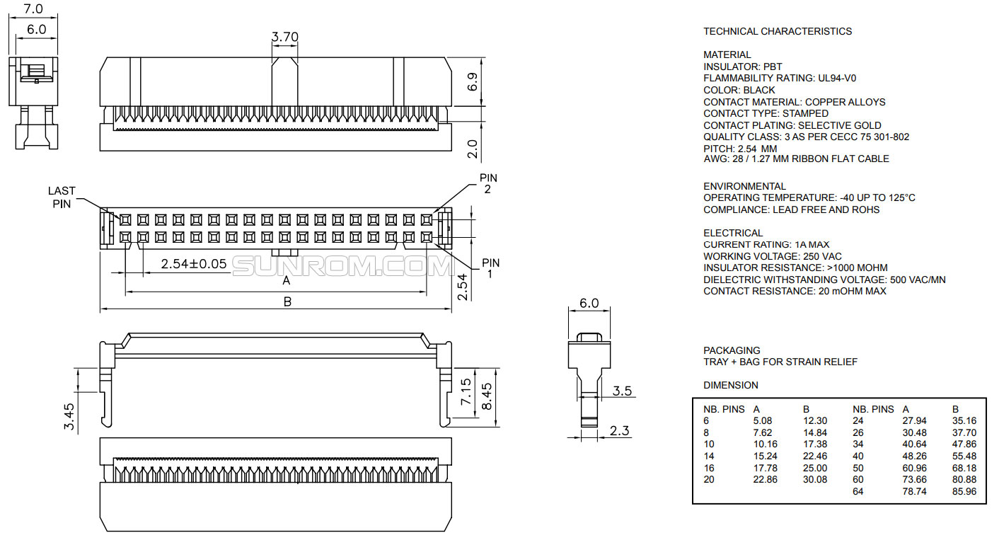
- 2.54mm IDC40 socket (or another size) and ribbon is the signal line of choice inside the box
- Best to cut large holes in the box with plates fastened with all the detail holes. This may void IP65 ratings. For this kind of box, it could be the right way.
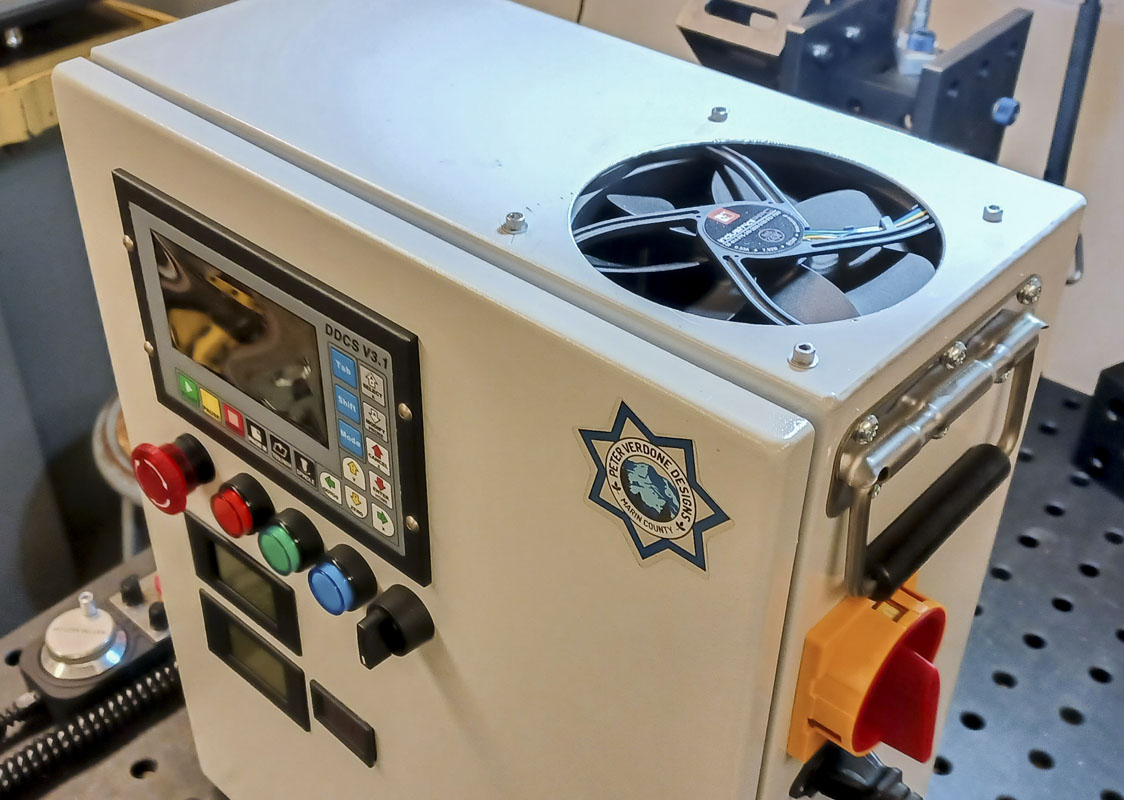
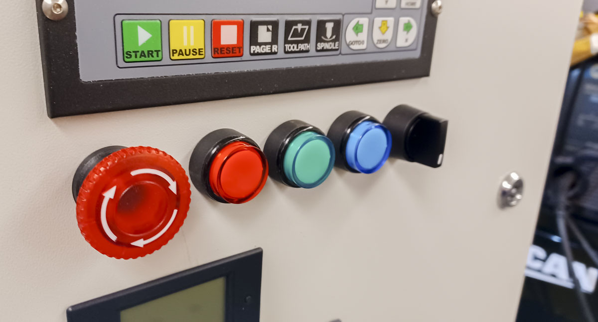
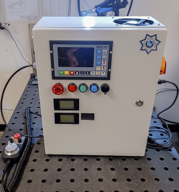
- The Auspicious LXL22 switches are nice and inexpensive.
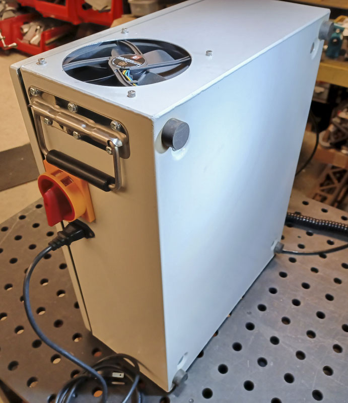
- Great handles and feet make things great! This is a worthy investment.
- Inexpensive components can be very good but always buy with caution on quality
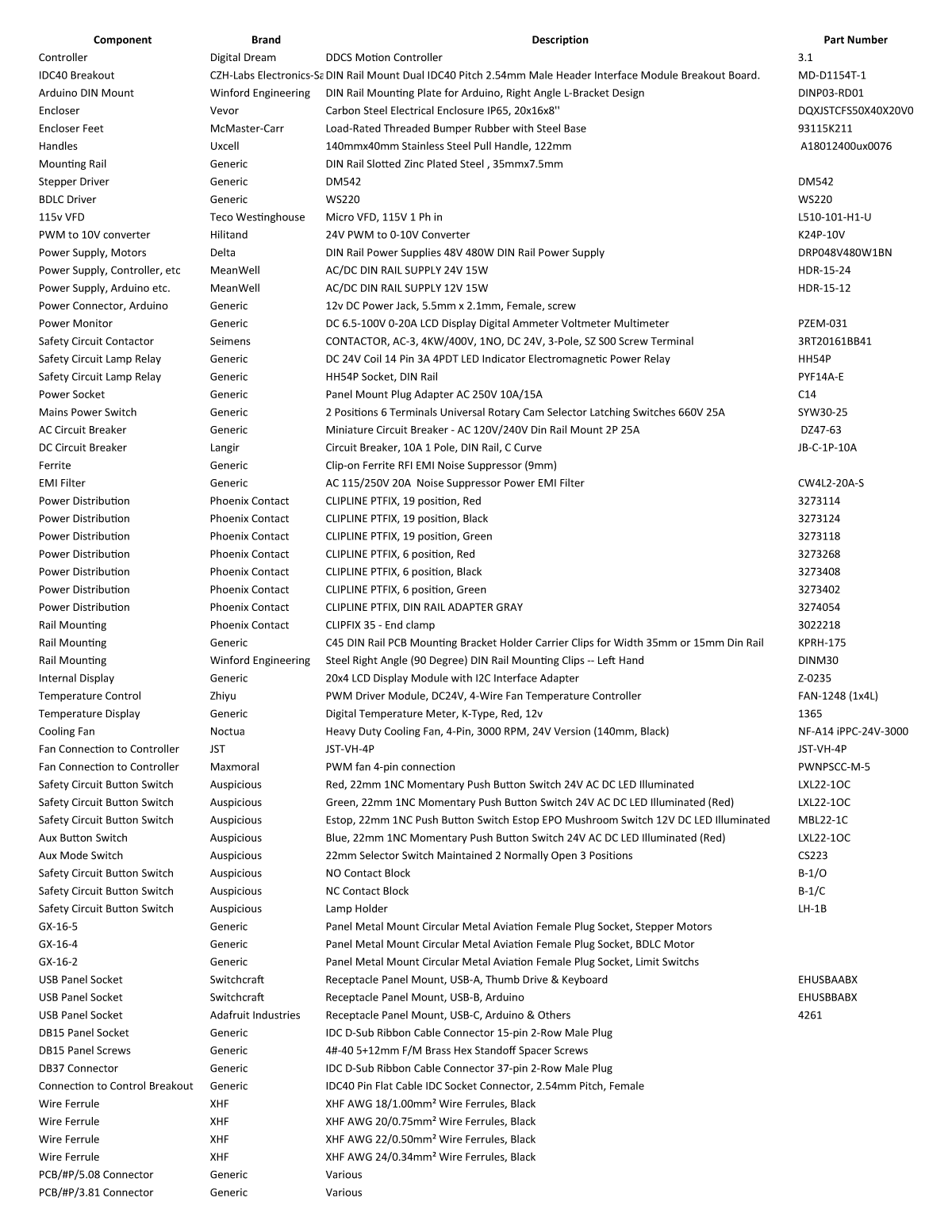
2023-03-17-2 CNC Controller Parts
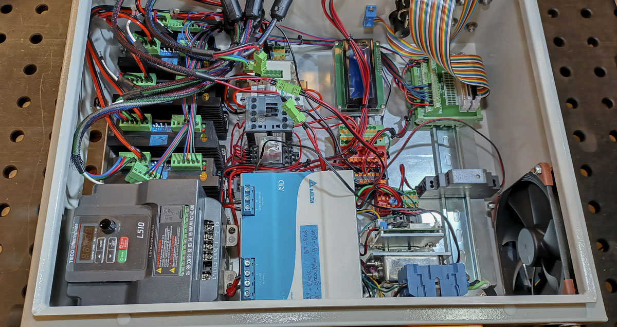
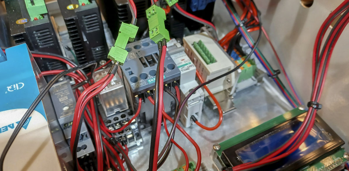
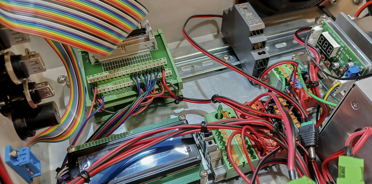
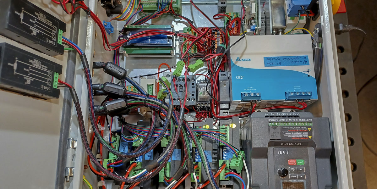
The inside of the ICP. I need to do some more cleanup. It’s also still waiting on limit sensor connections.
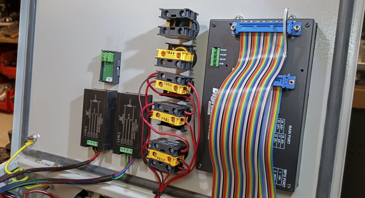
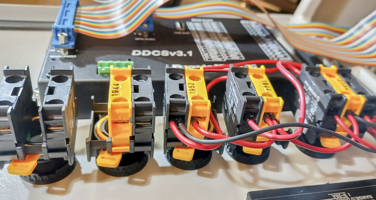
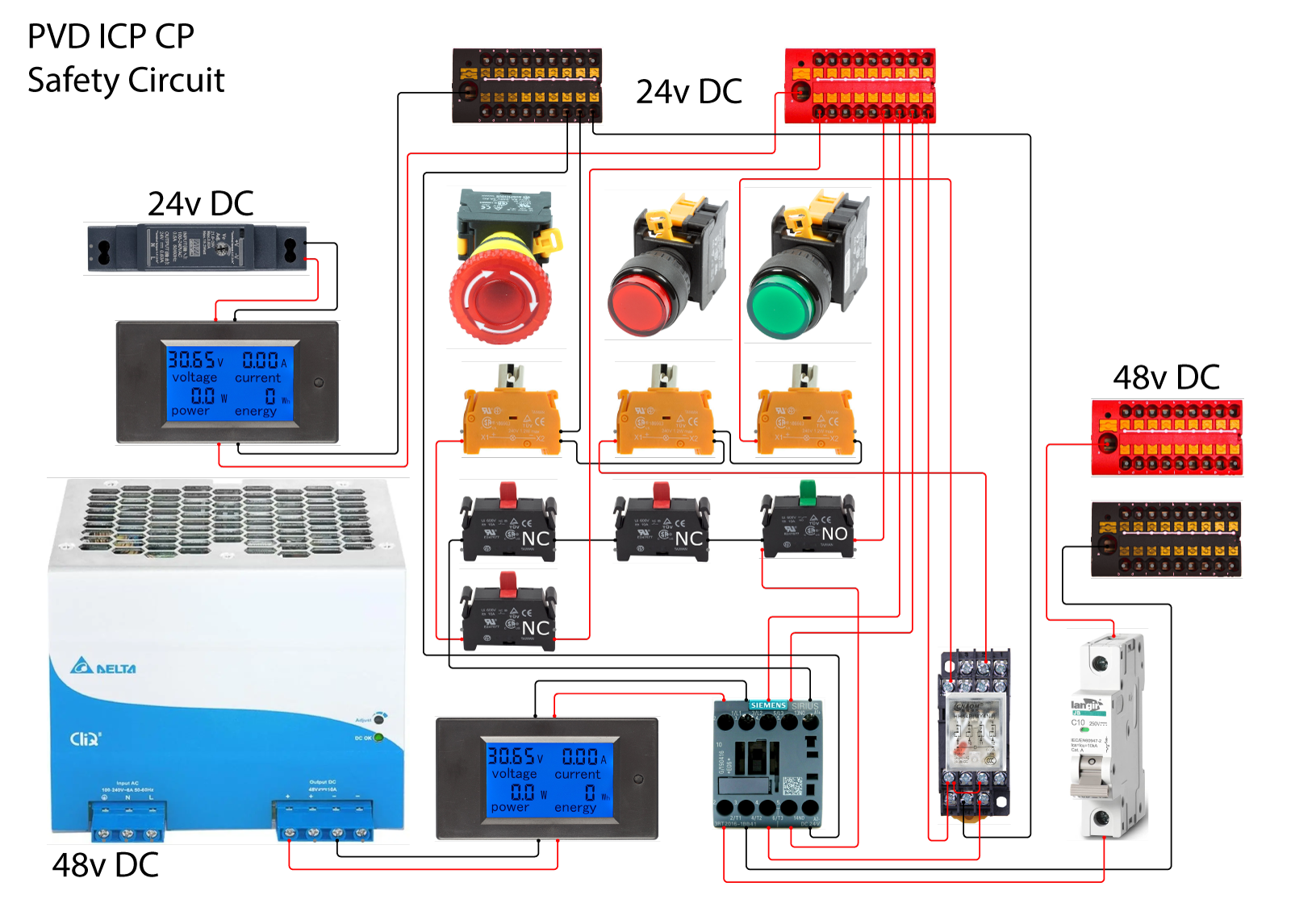
Here’s the safety circuit pulled out for clarity:
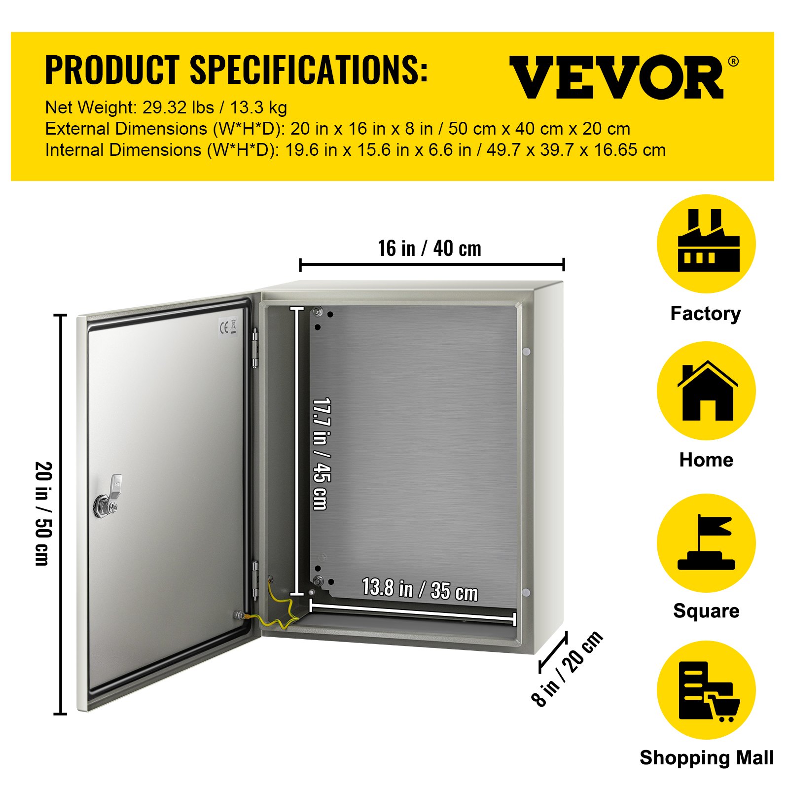
The enclosure is a steel IP65 unit from Vevor. 50 cm x 40cm x 20cm. The quality of the enclosure is very good and it’s extremely robust with 16 gauge steel (1.5mm/0.059″). It’s cheap enough ($129, free shipping) that I can afford to make mistakes if space and plans run out. It appears to be a branded Saipwell SPT-504020. I recommend these boxes.
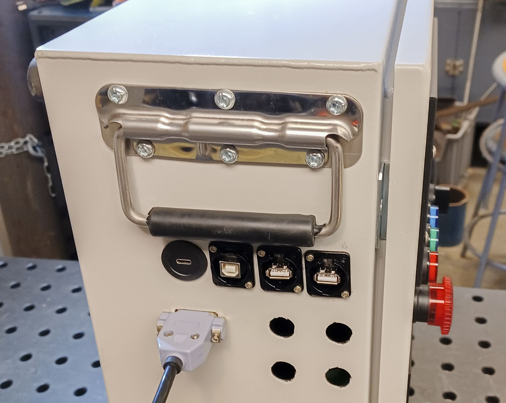
Cutting holes for buttons, connectors, and controls in the box just sucks and is full of all kinds of ways to make embarrassing mistakes. I was hoping to just make black anodized and marked aluminum panels to go over larger holes but that was a small project of it’s own. I needed to be expedient to get this thing moving. I can always do the larger cuts later when I want to go all in on a proven form.
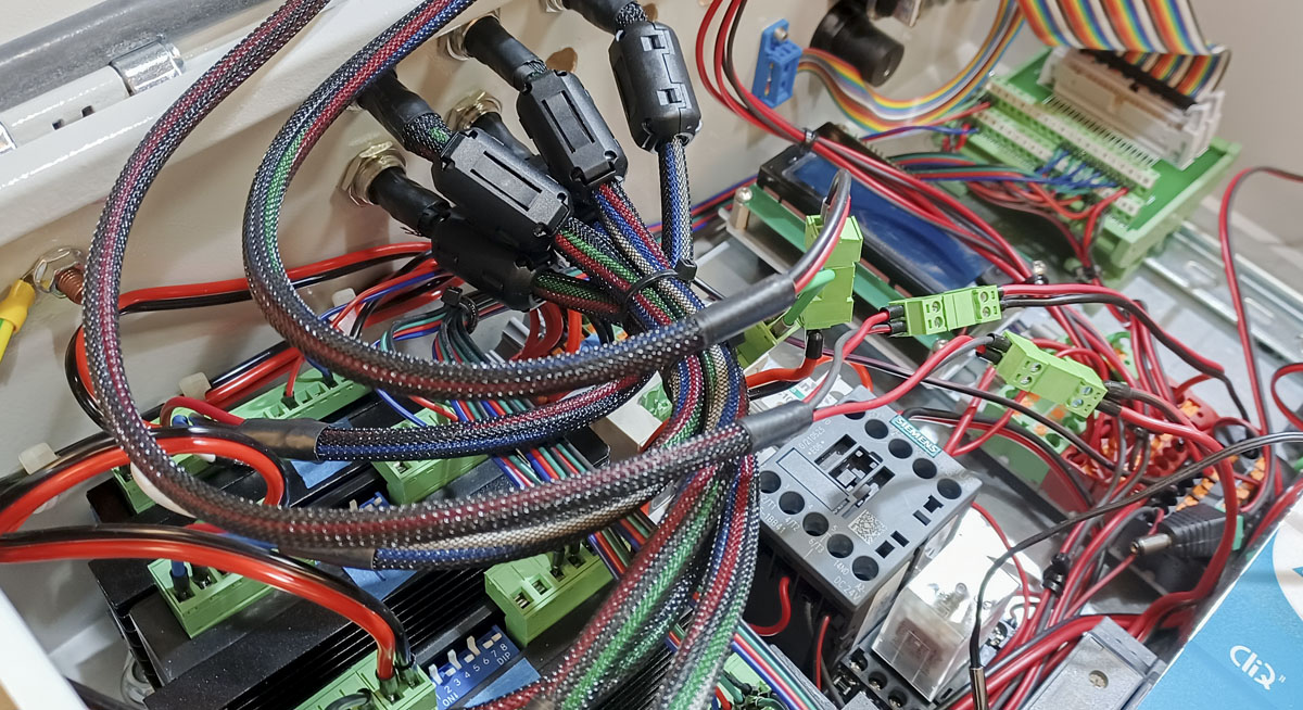
Laying out DIN rail is certainly a planning challenge. I found that a spacing of 100-110mm spacing between rail centers worked reasonably. Getting up to 120mm can take a little of the edge off of some component spacing. Moving to a 3 zone layout saved a lot of room in my box. That gave me a way to mount the very large power supply and VFD while still densely packing smaller components.
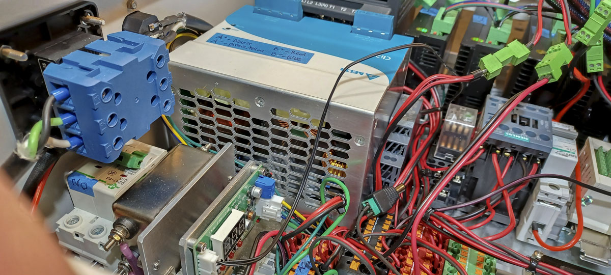
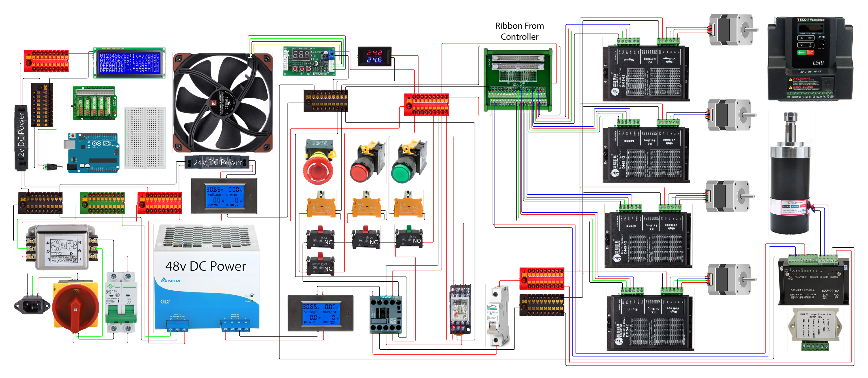
The goal of the power system was that the motor power would be 48v and that control would be 24v. This would give the motors a lot of bang and use common control parts that would be on a separate circuit.
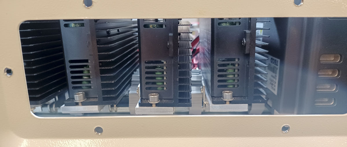
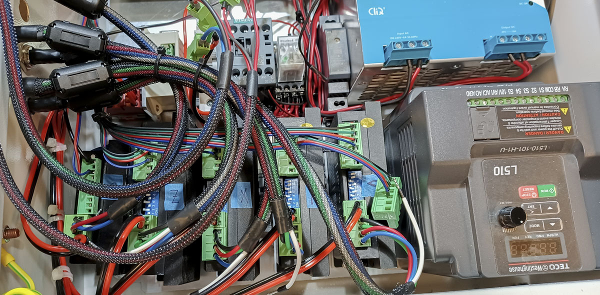
The DM542 stepper motor drivers and 48V (480W) power supply was ballparked for small to mid sized NEMA 23 stepper motors. I may be close to the limit there and will have to find out. At the least, I can get up and running with something for improvements to follow. I’ll keep my eye on that as I start putting loads on the system.
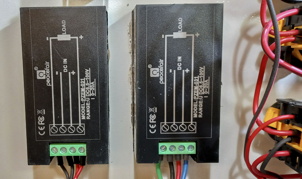
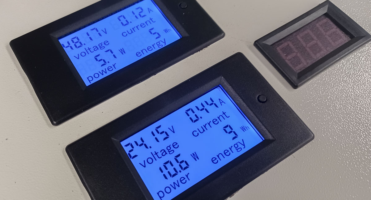
Some inexpensive power monitors on the front panel of the box show me how much power is coming out of the 24v and 48v power supplies. If I see use too close to the limit, I’ll know to size up the supply.
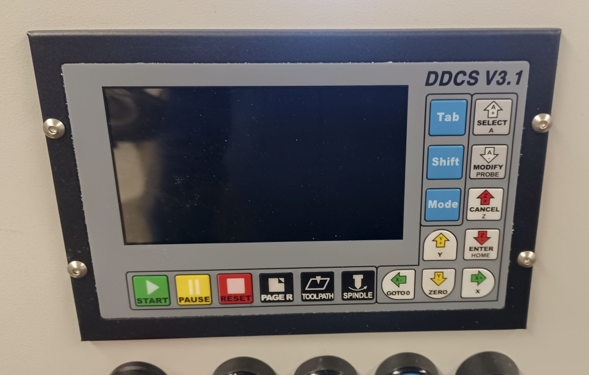
This is the back side of the DDCS 3.1 controller. It’s well labeled.
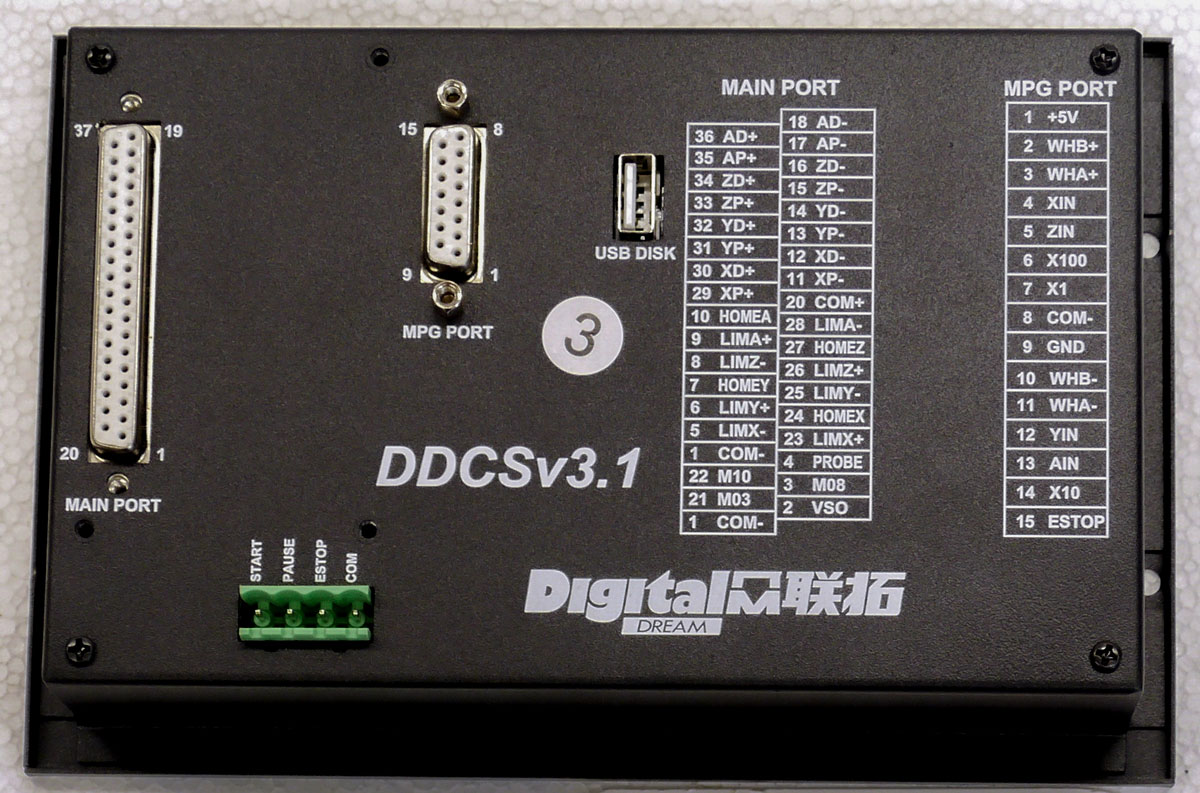
The connections at the rear of the controller are;
- DB37 – Main operating control
- DB15 – MPG Pendant
- USB – Data input
- PCB/4P/5.08 – Panel controls

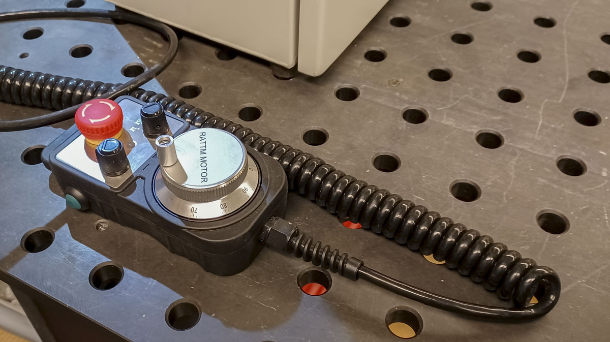
The pinouts for the DB-15 MPG pendant control. These are connected through the panel to the MGP.
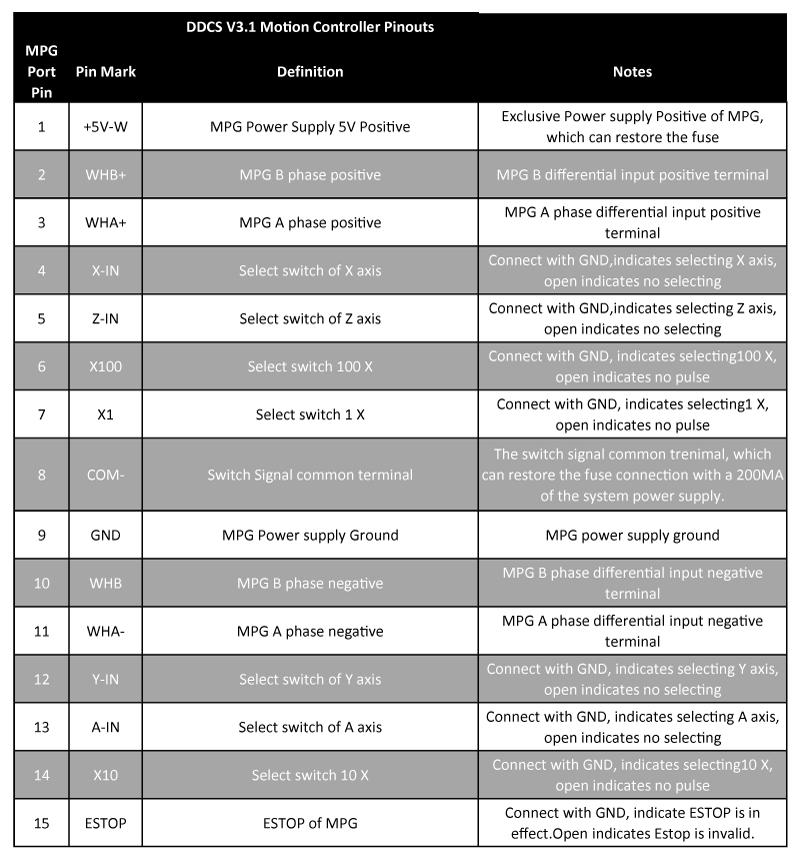
To make wiring of the controller more compact and cleaner than it otherwise would be, I decided to connect to the DB37 at the controller with a ribbon cable to a IDC40 connection. That would terminate at a breakout board that would distribute the connections around the box. This required a translation of the pinouts. Translating these connectors created some confusion but it ends up nice at the breakout board.

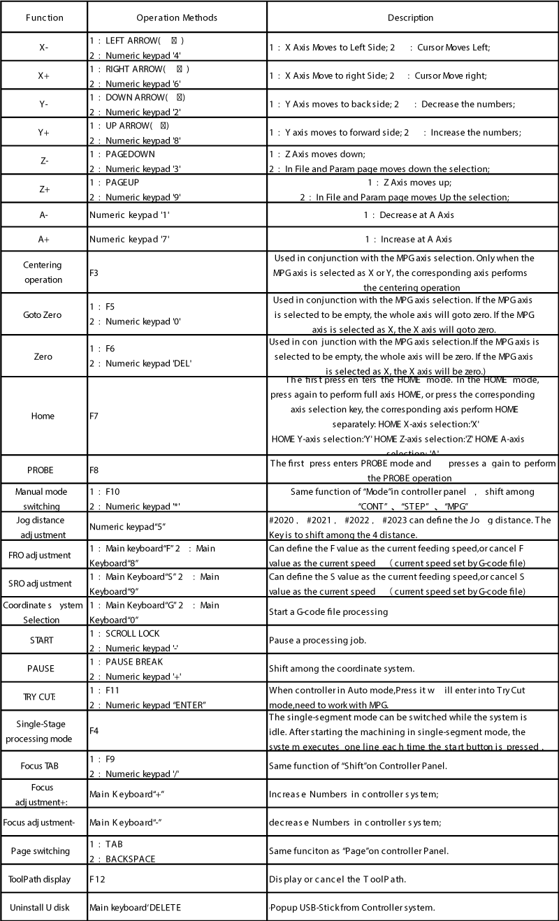
Using a USB keyboard, shortcuts also exist for the controller.
In initial setup and baselining of the controller, I’m not convinced that I like it. I’ll know more in time. I’m enclosing the settings below:
2023-03-17 CNC DDCS 3.1 Controller Settings
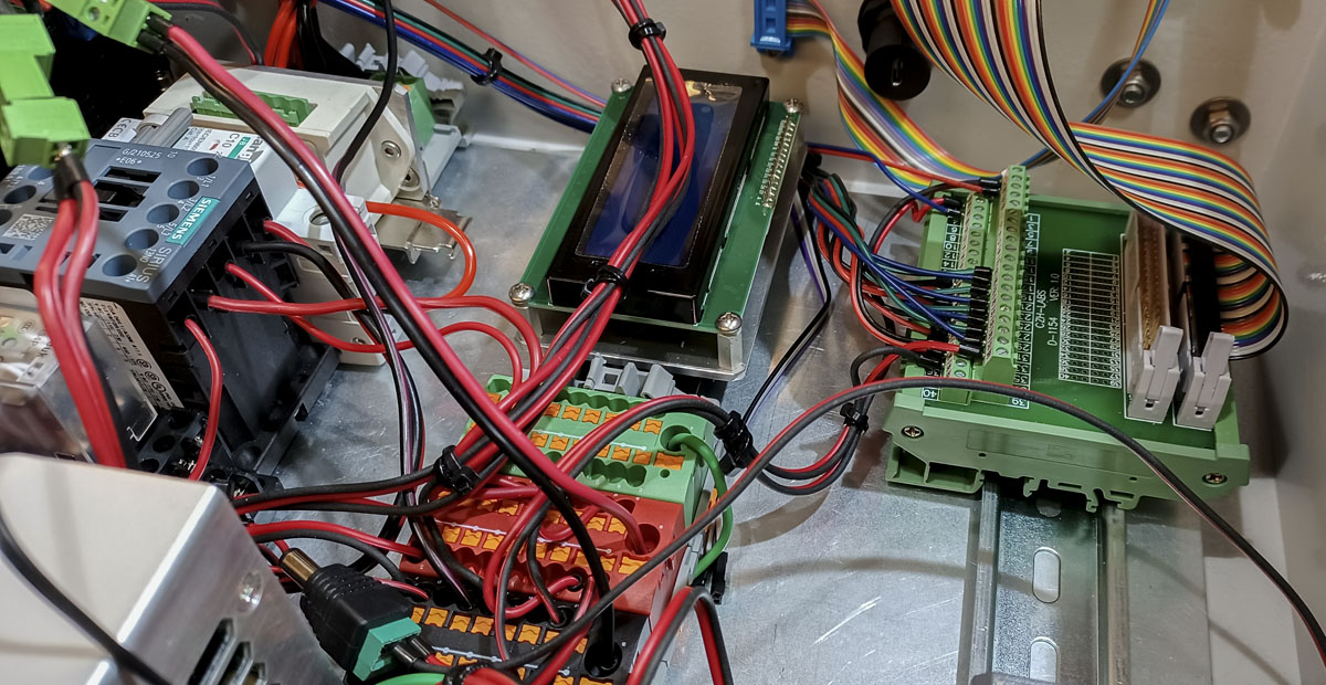
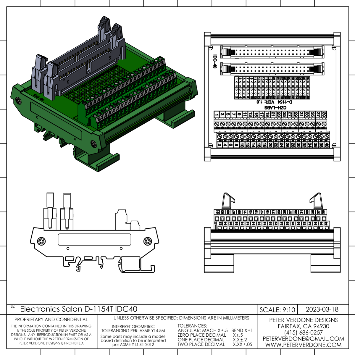
The Electronics-Salon MD-D1154T-1 make a modular plug-n-play control system possible. Just pin the control to IDC40 and everything else is done.
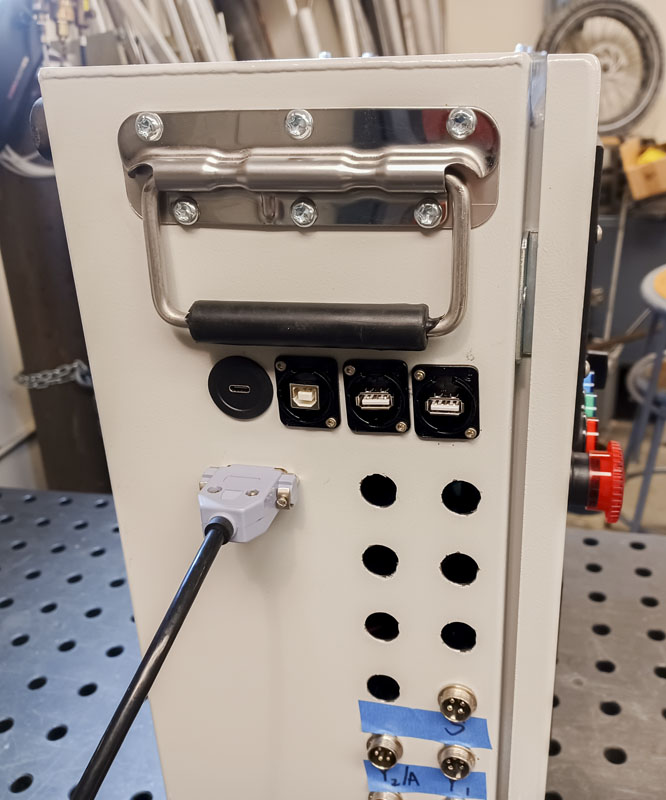
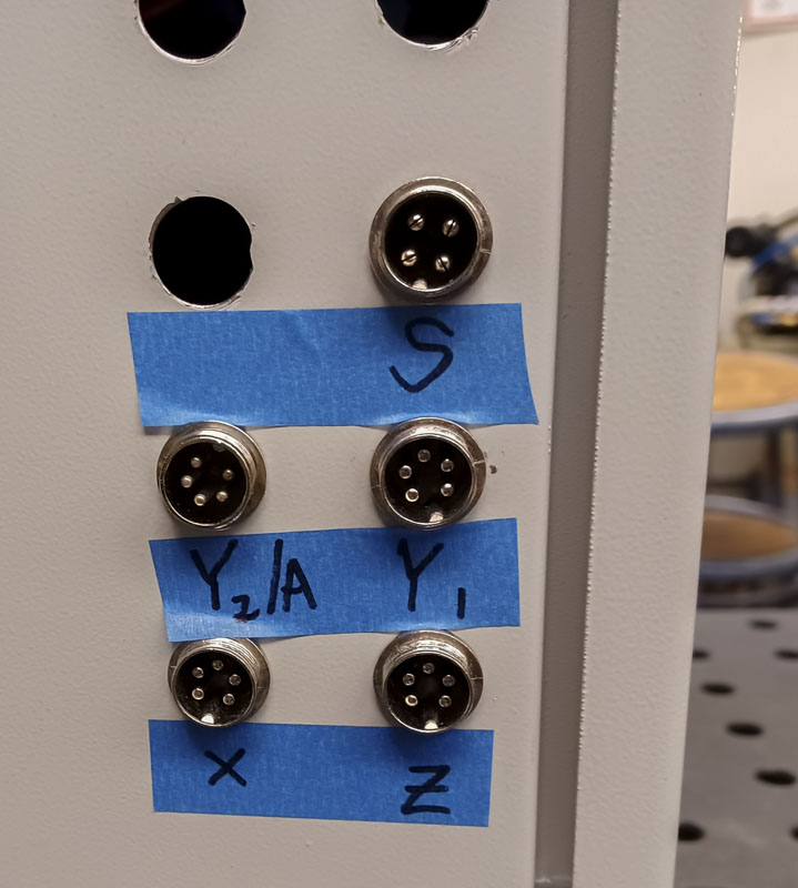
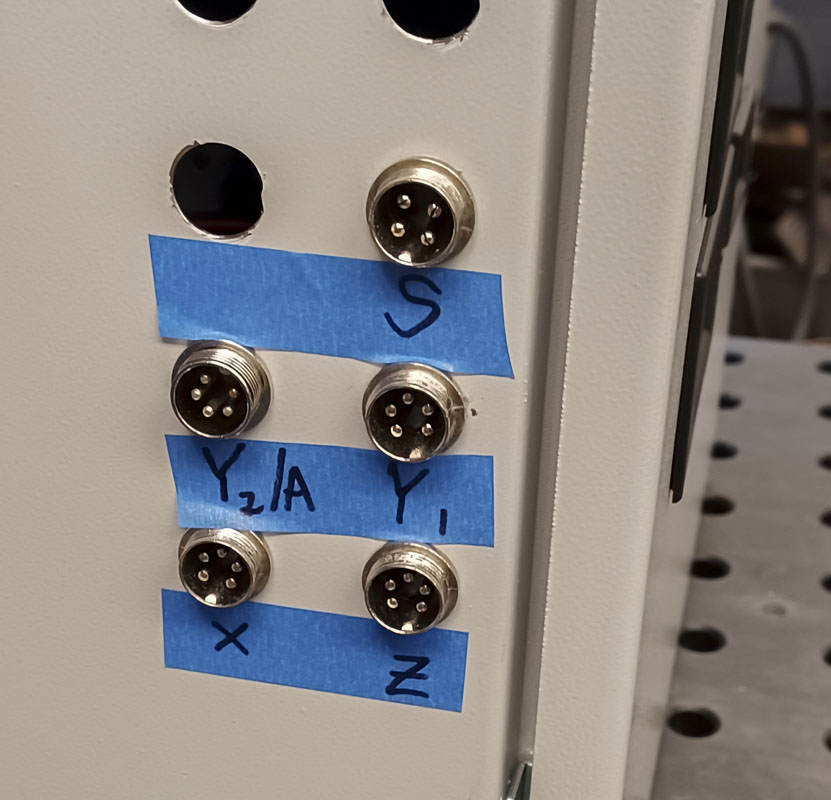
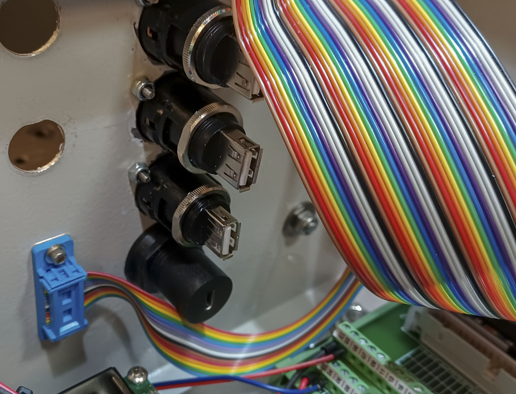
Until I find better, I’ll be using GX16 aviation type power connectors. This is common for this type of build. It’s cheap and works but it’s not very elegant.
I’m trying to find a better connection for the panel pass through as well as at the machine end. It would be secure, inexpensive and seem like a clean solution. I’ve found some but they are more spendy than I like. If I had samples, I’d be more willing to spend the money. That’s the hard part with this kind of thing.
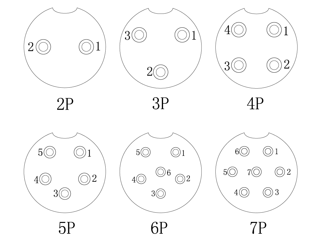
Stepper Motors – GX16/5
- P1 – A+, Black
- P2 – A-, Green
- P3 – Ground, White
- P4 – B-, Blue
- P5 – B+, Red
Spindle – GX16/4
- P1 – U, Red
- P2 – V, Blue
- P3 – W, Black
- P4 – Ground, White
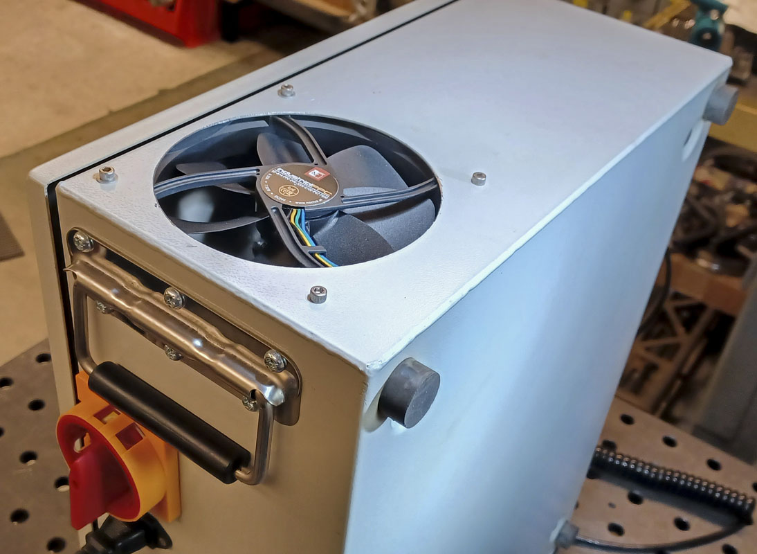
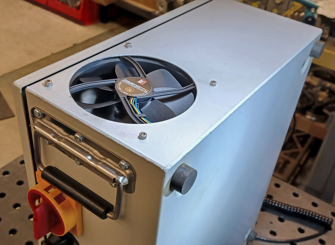
The box is not finished. I still need:
- Bezel for fan on the top of the box
- Filter screen for the vent at the bottom of the box
- Wire VFD with protection circuit
- USB connecting wires
- Wire panel eStop to controller
- Connect front temperature display
- Limit screw connections at the side of the panel.
- Coolant control panel output
- Refine wiring for gauge and cleanliness
- Fully test box in operation
- Ground motor cable/s connections
- I need to go over all my grounding. Just to make sure.
- Wire labels! This is left for the next big dive.
- Should a ‘fast blow’ fuse be added to the system?
- Should Molex Micro, Ultra, or Nano fit connectors be used internally?
- I need a data plate on the box!!