2024-10-25 update is HERE
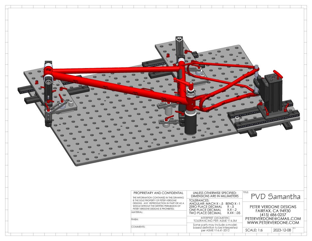
Thanks to our evolutionary push to modern bike design, back in mid-2020 I brought the PVD Cyberdyne bicycle frame fixture into the world. Since, I produced designs for the SKYNET (2021) and WOPR (2022) frame fixtures. Now, in 2023, we have the big update. Samantha !!
The first 3 fixture designs were each different enough from the other to be considered new designs but all using the concept of building from a rigid, flat, raster surface. The breadboard style fixture. Because very few others have put much time into developing this method of fixturing bicycle frames, there has been plenty of ideas designed into them that were novel and innovative.
This is another take on the theme and hopefully the last major architectural shift, Samantha.
Making this different than the original SKYNET fixture design are the host of improvements and that the goal isn’t to be as cheap and as easy to make. In addition, the pivots for the head and seat tube rails has been moved from the bottom to the top side of the layout. My goal here was to build on the SKYNET to discover it’s real potential based on all the designs and experience in the past few years. This will use more expensive CNC parts, but most of those are fundamentally common throughout the design keeping the cost down.
Without forcing folks to read up on the last 3 designs, they are built on a fixturable surface plate that allows for commercially available extendibility that can locate tooling or parts anywhere on a pre-existing Cartesian raster. Plates move over other plates. The plates are thick steel, extremely rigid, and cut to very tight tolerances. There is a huge BuildPro/Seigmund ecosystem of (comparatively) inexpensive tooling to be used anywhere that is convenient or imagined.
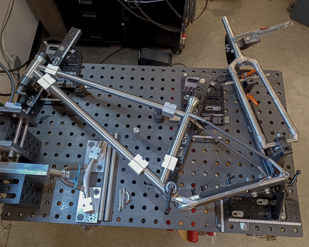
On the frame design side, almost any imaginable bicycle geometry can be produced; circus bikes, juvenile bikes, WC downhill race bikes, tandems, whatever you decide using one table or a gang of them.
For full suspension bikes, this is simply the only logical way of fixturing. Pivot and shock mounts can be located with exacting precision anywhere on the bike with very inexpensive tooling. This system is optimized to handle interrupted and highly offset seat tubes, as the tube can be held precisely at any point in it’s run and at multiple points.
As this is intended as a prototype/toolroom fixture, highest volume production is not the intention. Rather, flexibility, precision, and value are the goal. By investing in a proper table, it can be used for other high return fabrication projects, as a machine base for bending and coping tools, a simple welding table, and a frame alignment table. If the table is built into a rotisserie, it can be rotated vertically, used as such, then rolled to the side of the room to clear shop space. Flexibility, precision, and value!
In the past 3 years of using the Cyberdyne, I’ve found issues that I loved, others that I hated, and also just a basic familiarity with working in the ecosystem. This informs my current decisions.
Without a doubt, the biggest problem with the Cyberdyne was the rastered slot positioning. This is fine enough to work with but I wouldn’t do it again. It makes the setup process far more cumbersome than is necessary. The design came about as a handicap in that the Cyberdyne was meant to work with a welding fixture plate as well as a scientific optical breadboard. Since, I’ve totally given up on the use of the optical breadboard in favor of the welding fixture plate. The advantages of this choice are numerous and have wide ranging effects. It frees me to open the design.
I’ve learned a lot about using and designing for the ecosystem of the welding fixture table in the past few years. I’ve found that tooling development can pass from fabrication to machining and back. That money and time producing a tool to solve one problem can become a building block for another. It’s industrial fabrication Legos. Now, when I produce a design, interfacing to this system directly or through 8020 t-slot framing is where it begins. My cost in money and time go down in the aggregate and my capacity increases as time goes by.
I construct all of my integrated handlebars on my table. I’m hoping to produce a fork fixture soon. Think about the ability to make a fork as long as your fixture table.
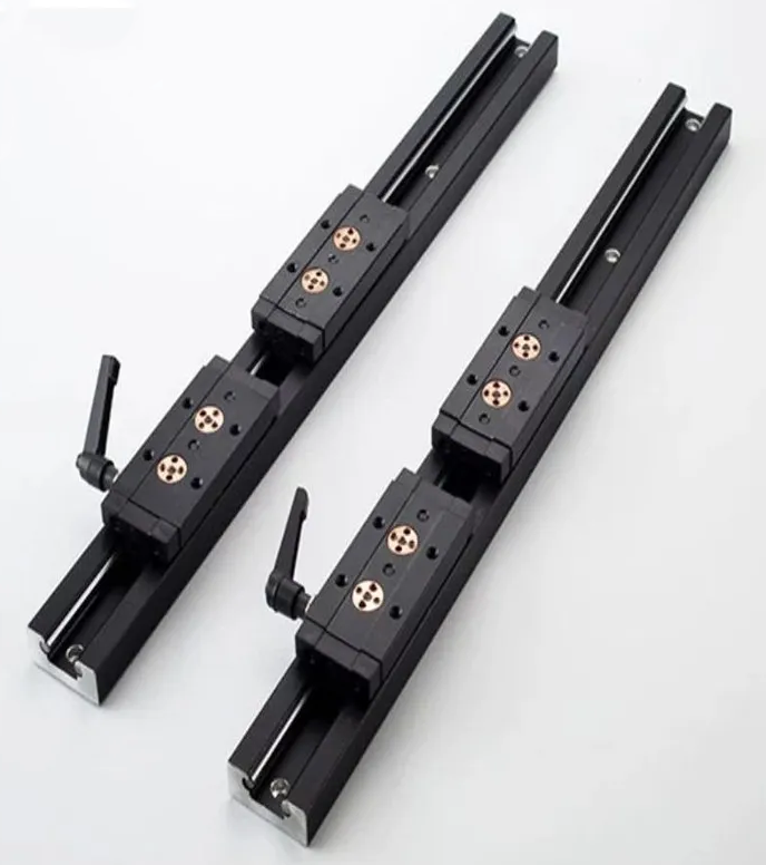
So, a few weeks ago, I was looking into updating the Cyberdyne fixture that I use with some type of rail that could replace the rastered slots. I looked around at various linear rail systems. Finally, I got some SGR20 rail with locking 5 bearing carriages. Why not be fancy? While these are an excellent problem solver, they simply didn’t get through the engineering to prove it was correctly used in this design. They constrained design too much in both scale and direction.
Instead, it was back to 8020 like the original SKYNET. The reason for using 8020 for linear position is simple. It’s very robust, widely available, precise enough for fabrication, and it’s cheap. The positioning that is done for this design is relatively simple and not highly dynamic. We want to move the plates with ease but then lock them solidly in place. Introducing artificial complexity into that would make the design worse, not better. While there are other brands of t-slot framing that are arguably better for this use, the ubiquity of the 8020 sitting in shops and available through common suppliers like McMaster-Carr push this choice over the line. Ubiquity is important.
This led to more digging into how to update the Cyberdyne and I had an epiphany. Why am I trying to make precise and rigid plates when they already exist in the ecosystem that I’m trying to interface with? If I just purchase a BuildPro TM57846SV-01 (46 x 6-1-4 x 5-8) plate and cut it into 3 pieces, I’d have the plates that I needed for a whole fixture. These would be flat, stronger than anything that I’d make, and already have a precision breadboard on them.
It was then that this project blew up on me and ate up a few weeks of my time. I was beginning to see what this fixture should have been all along. I wanted to chase down every possible detail to make this one cheaper, easier, more precise, more rigid, easy to build on, and easy to calibrate.
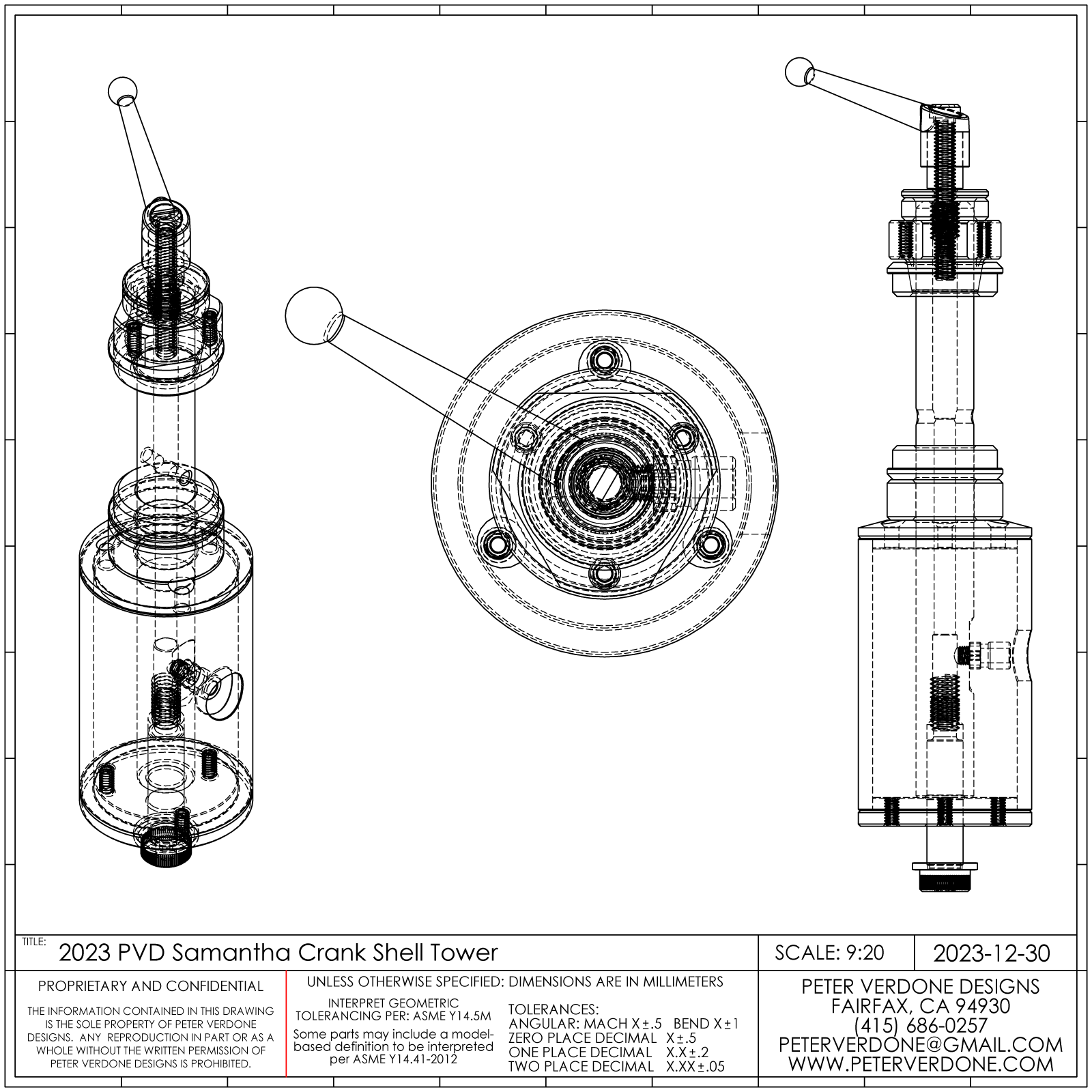
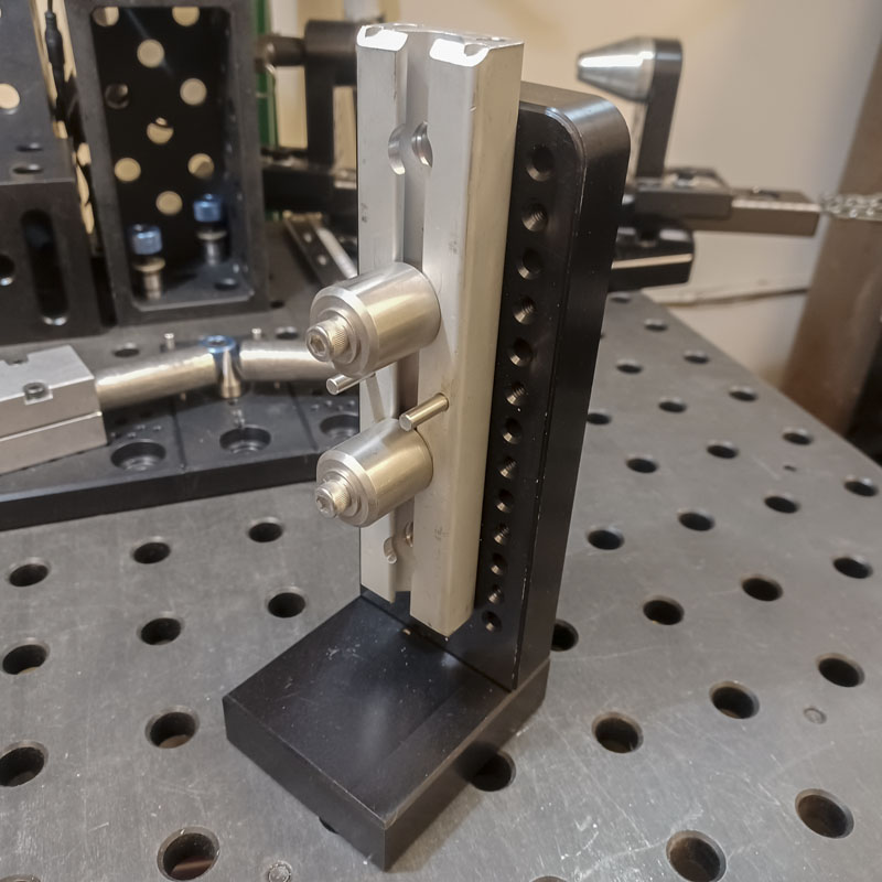
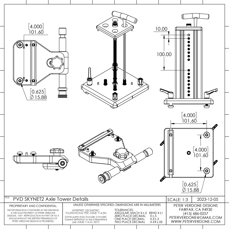
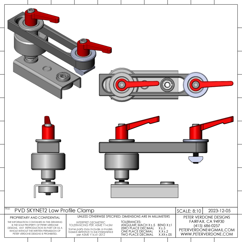
That’s another problem with the Cyberdyne fixture, it was very difficult to calibrate the rear axle holding component. Sure, we can strive for perfect production and assembly but fine tuning is always needed. Remember, just a very slight amount of misalignment of the rear axle holder gets magnified out 300mm or so to cause the tire to be visibly off between what might be perfectly placed stays. I developed a nice tool to help with this adjustment but the fixture made that quite challenging to do. In the new design, high pitch set screws can be adjusted to tilt the axle tower over the table in any axis. Once done, a single nut tightens the whole structure as one.
There’s a lot going on with the axle tower:
- Calibration system
- Quick removal of dummy axle
- Centerline adjustment in 10mm increments
- Tower counterbored for use directly on breadboard
- Axle holder counterbored for use directly on breadboard
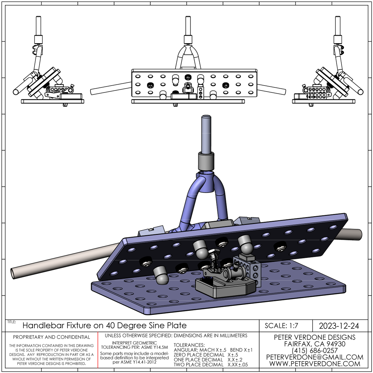
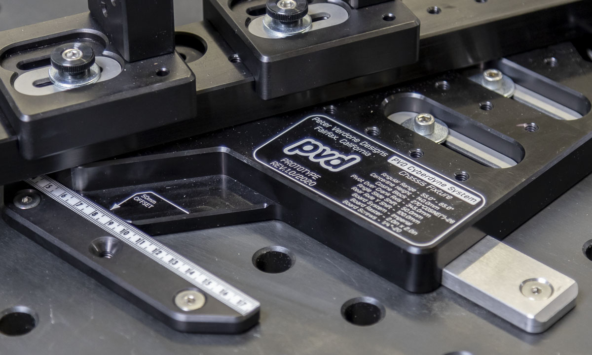
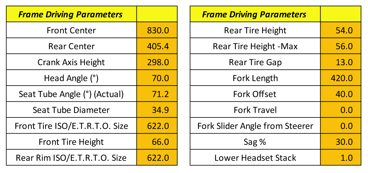
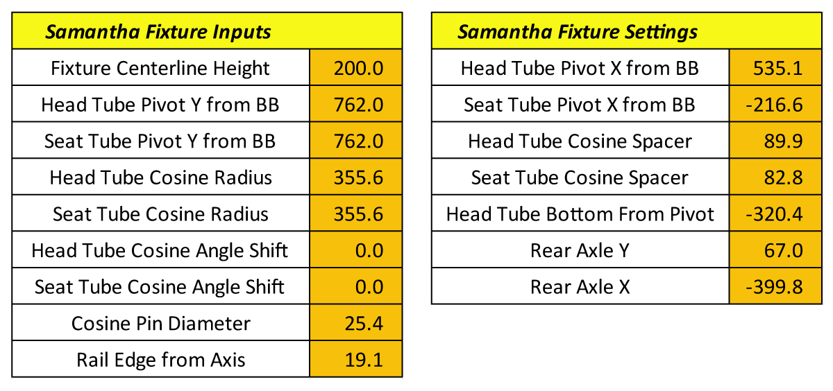
As usual, fixture settings are produced using a calculator. The driving parameters of the frame to produce and the configuration of the fixture are input and settings are output. These values end up being quite precise as they are produced directly from driving parameters.
Notice in the fixture inputs that the Samantha fixture uses a 14″ cosine bar (longer or shorter). This really is an absurd level of precision built right into the fixture for angular adjustments. At 70.0 degrees, a 0.1 degree change in angle is produced with a 0.023″ (0.58mm) offset change. That’s a lot of resolution. I don’t believe that it’s possible to set angles as precisely on any other fixture. Since the cosine pin can be placed anywhere from the pivot that is available, the bar can be longer, shorter, or even at an angle from the raster. Cool stuff.
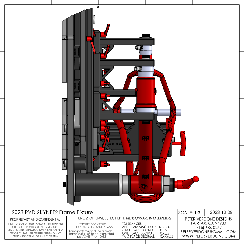
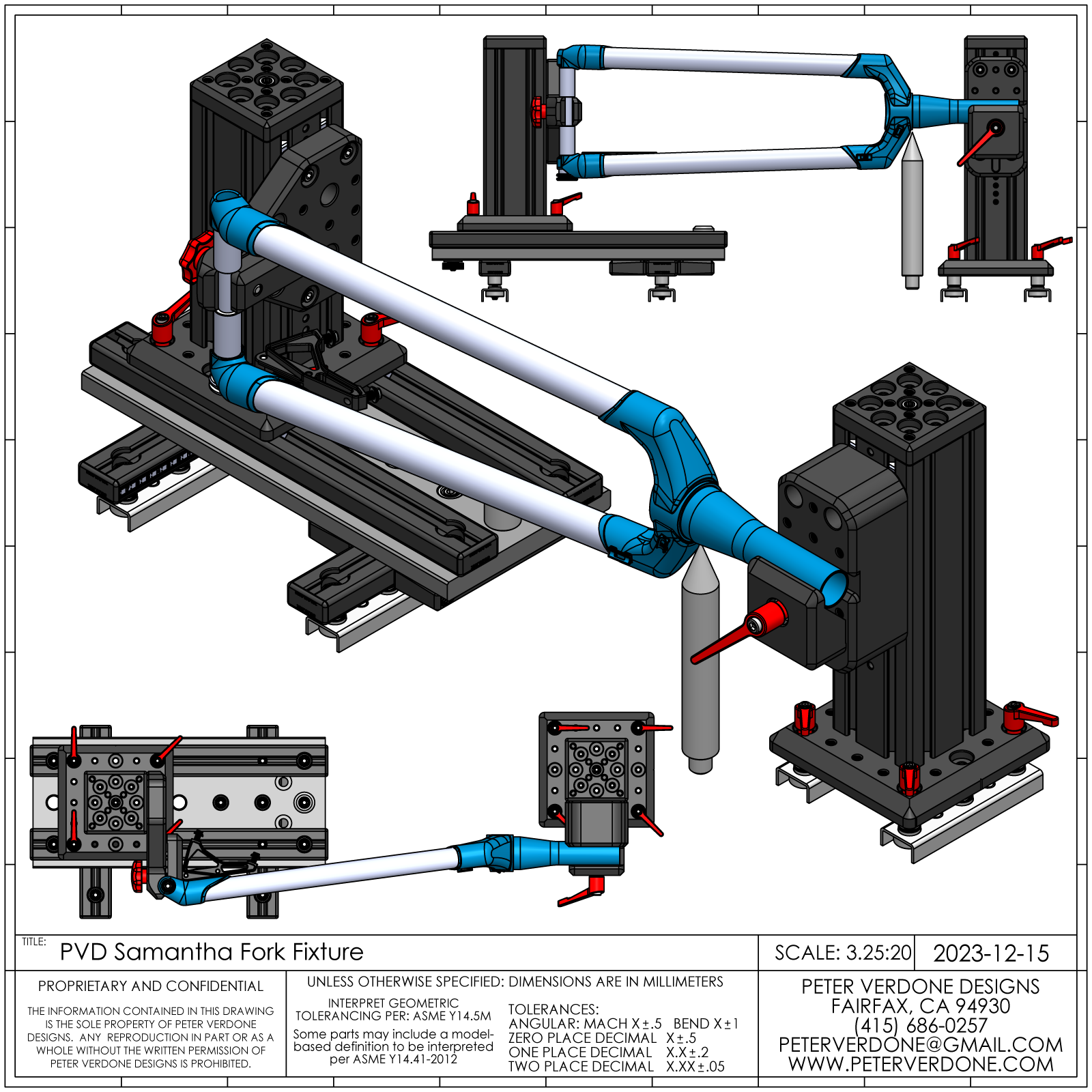
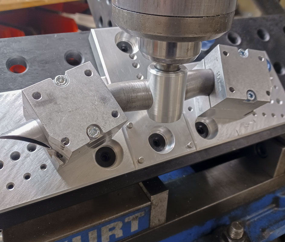
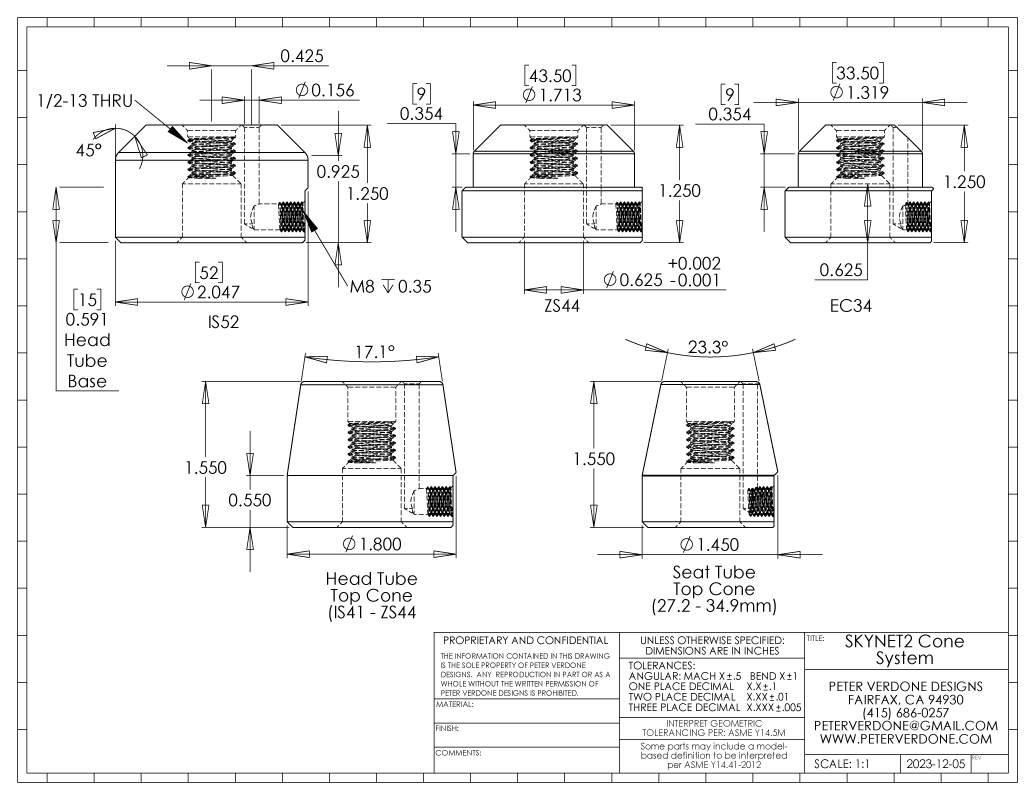
I believe that I’ve finally figured out the cone system for fixtures. It’s a simple system that uses 5/8″ shoulder bolts through a 5/8″ or 16mm bore. This makes connection simple and precise in whatever situation the cone is used. More, the shoulder bolt can be removed quickly to allow the frame to be removed from the fixture without upsetting any of the settings. Obviously, using this method is to allow the cones to be used in other fixturing situations in the fixture table system or developed tooling. Since the pin is designed for 5/8″, a simple stainless 0.002″ shim can be used over the pin to fit 16mm tooling. Below is a sample of the system of how it can be deployed. Purge plumbing can be omitted but has been considered.
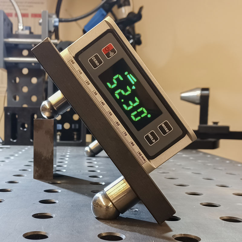
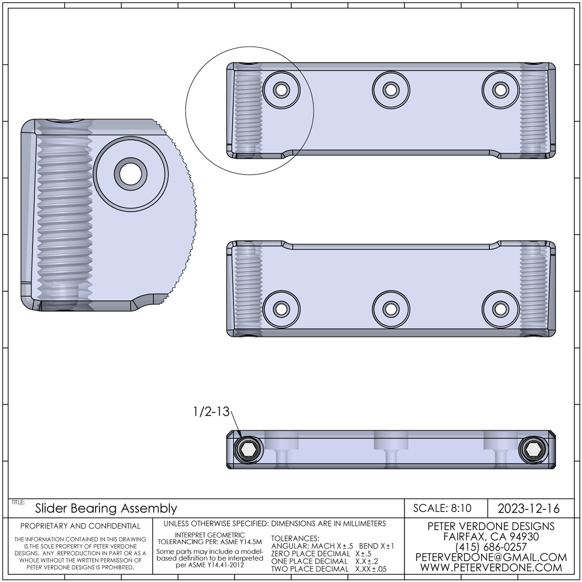
Because this fixture is leveraging the power of the BuildPro/Seigmund ecosystem, it’s easy enough to clamp the angle beams in place with Inserta Clamps T-Handle (UDN5150). All kinds of tools could be used for this. Still, because I wanted the utmost in cleanliness in this design and to solve a special problem, I developed another kind of clamp. It’s low profile and integrates the BuildPro T50632-01 D-Stop Bar (T50505, T50510, T50517 Straight Edge Stops). Essentially, it’s an upside down table clamp that will fix the beams at the bottom. Snazzy. Again, leveraging the ecosystem. This makes for a very flexible clamping system that can be used in other setups or as component parts.
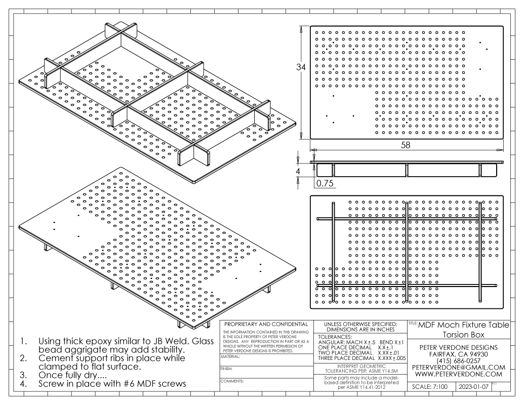
Many are critical of this type of fixture, saying that the cost for one of these tables is too much for them. I get that that may be a big hurtle. But this is the magic of a modular and scalable ecosystem, you don’t need to make it perfect at first. Instead, each part of the system can be made reasonably good enough at first and updated later when funds and skill meet. Below is a print for a MDF tortion box surface that can be made from a single sheet of 3/4″ MDF. For someone good with their hands, this would take an afternoon to produce. Even quicker if they have a friend that can cut parts on a cheap CNC router. The point here is that we want to be swimming in the right pond, not just the one that’s in front of us.
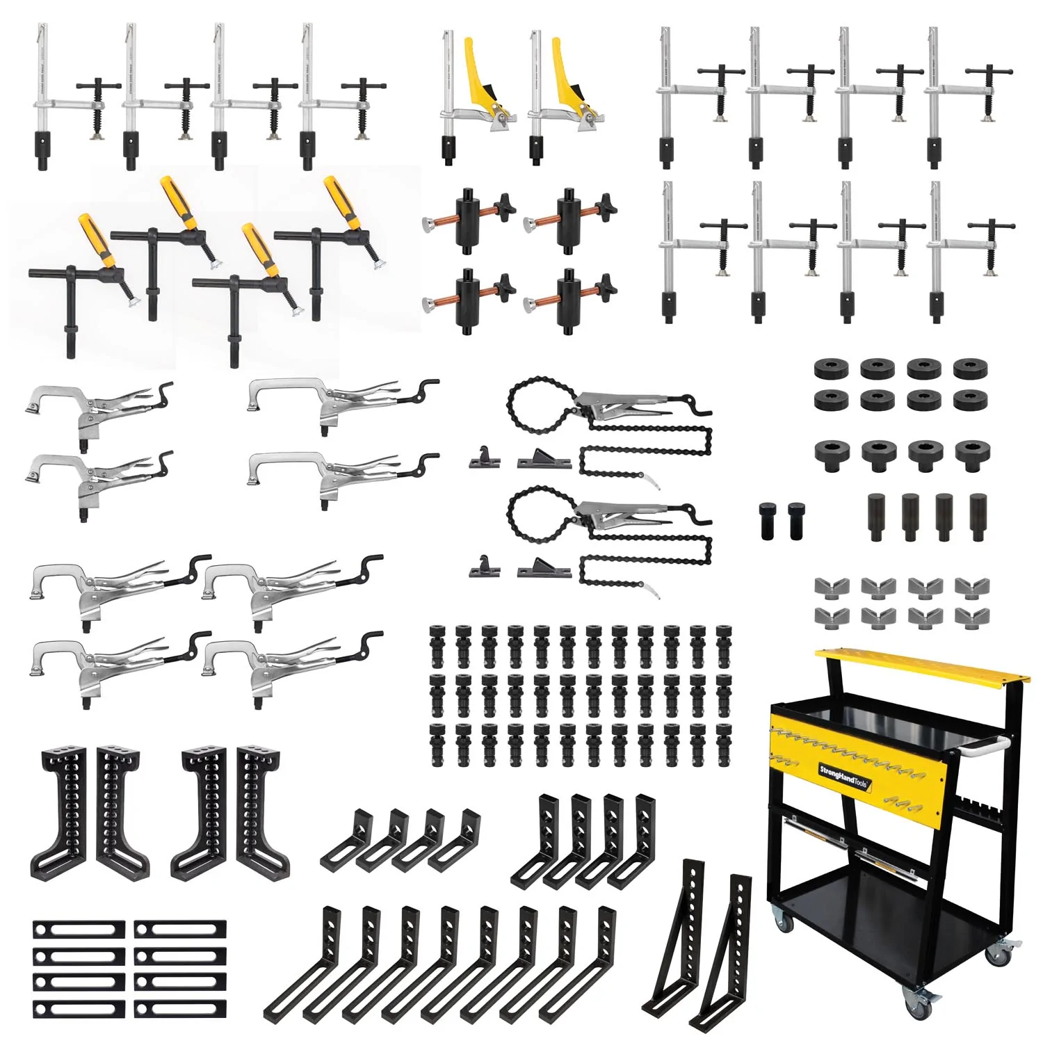
Here’s another argument. A BuildPro TD5-4830Q 48″ x 30″ x 5/18″ plate costs about $2,000. A basic Cobra Creator fixture is about $5,000 and a Sputnik is $5,500. That means that you could buy a table top and $3,000 worth of tooling for it for the same price as a turnkey dedicated frame fixture. This is what a $3,000 Buildpro TMK840 kit looks like:
There is an unresolved question that now surrounds the t-nuts. Currently, I have a negative key cut in the slides over the 8020 rail. There are good things about this. The sliders can simply be clamped to another surface. The tolerances are a little less stable than if a positive key were cut in the plate. I’m a little lost in this choice but have decided to chance this direction.
Another continuing question is, is it better to buy a metric table and tooling or an imperial table and tooling? I’ve been working in this space for the last 3+ years and I still don’t know the answer to that question. Without question, it would be easier to make tooling for bicycles using a metric table. Everything will just work and everything that comes up with bastard tooling wouldn’t be an issue. I that was all I expected to do, the choice is obvious. But, I live in America in American shops. Imperial tooling dominates this space and extending outside of 5/8″ x 2.0″ fixturing will turn into serious money quick. I want to do as much as I can with this tooling. That pushes me more toward Imperial. This space has been changing rapidly in the last few years and these decisions may look quite different in a few years. We will see.
Now I’m in the position of having developed this nice fixture. I’m thinking that I’m going to just bite the bullet and produce one for myself. Maybe I can partner with someone else that has an idle CNC mill and wants a fixture also. I’ll see how that goes and what refinements are needed. Then, we might see where all of this goes.