This is an exciting new tool for me and worth taking a look at if you build bike frames!
I’ve been needing this tool since I started building my own bikes. I probably could have even used it before that. I finally got around to designing and producing it. I’m sure that many others will feel the same way when they understand it. Let’s look at where this comes from.
The rear end of a bicycle frame is the hard end. Most often when building a frame, we have a scant reference from somewhere on the frame fixture to align the stays, yokes, and the various attachments that make up the rear of the bike. Depending on the fixture or the situation, that setup can be difficult or vague.
The problem is that most of what happens at the rear depends on where the rear axle is. It would add a huge amount of capacity to making the frame to be able reference directly from the axle axis while the frame is in the fixture (or even out of it). This would also make calibration of the axle axis in the fixture in an easy thing to do. Basically, since the wheel axis is so critical, we need to have a way to see how the frame relates to it, not just how the fixture does, and better that this be before parts are welded fast.
This is what we call a wheel tool. Wheel tools have been around a long time. Some have been more useful than others.
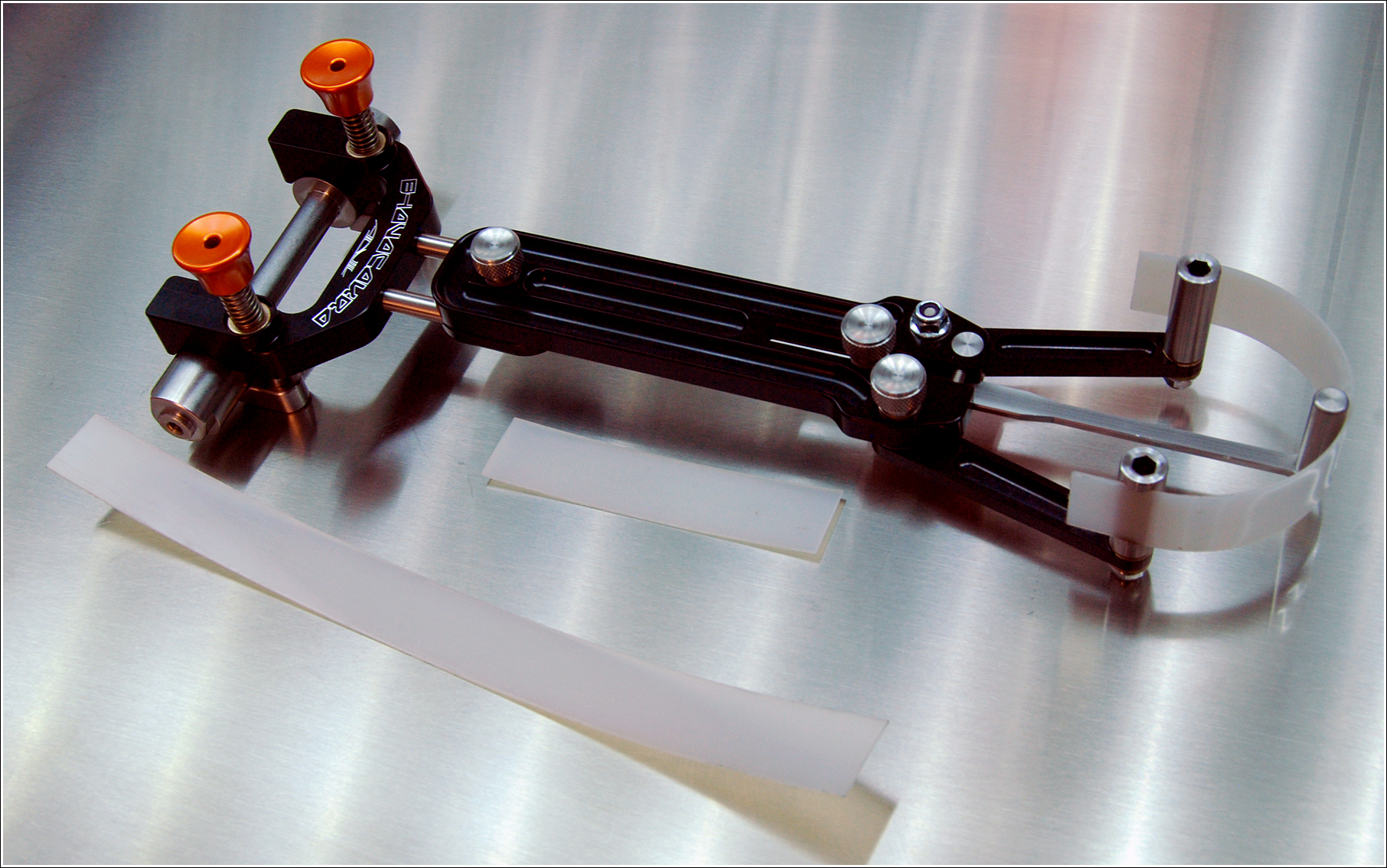
Back in the day, Don Ferris, at Anvil, had been producing a tool, the Bhavacakra (aka the Builder’s Wheel, circa 2015) to give the framebuilder a view of where the tire would end up in the frame, while the frame would be in the fixture. This was a pretty cool tool but I never got one. They were also done toward the end of Don’s run. It was very expensive and had limited use. It was very nice that it could be used in the frame fixture. I never owned this tool.
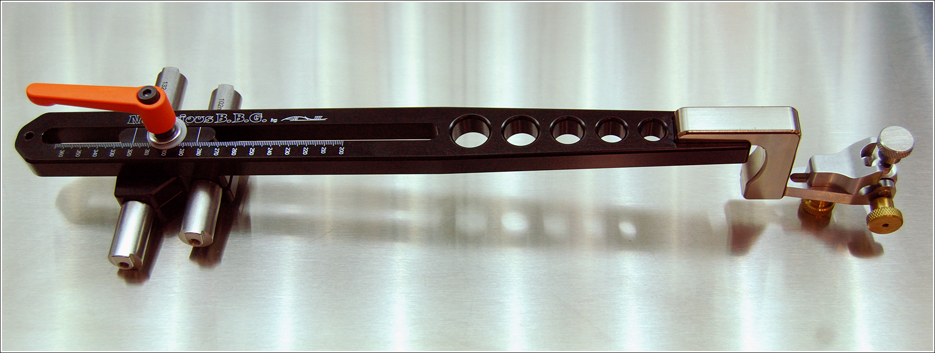
The tool that I do own is an Anvil Notorious B.B.G. tool (circa 2009) with all of the attachments. It’s a very useful tool but it lacked the level of precision that I need for many uses, plus I have to remove the frame fixture axle holder from the fixture to use it. There was a lot of play in the system that reduces confidence in measures. That’s not very good when working on a project.
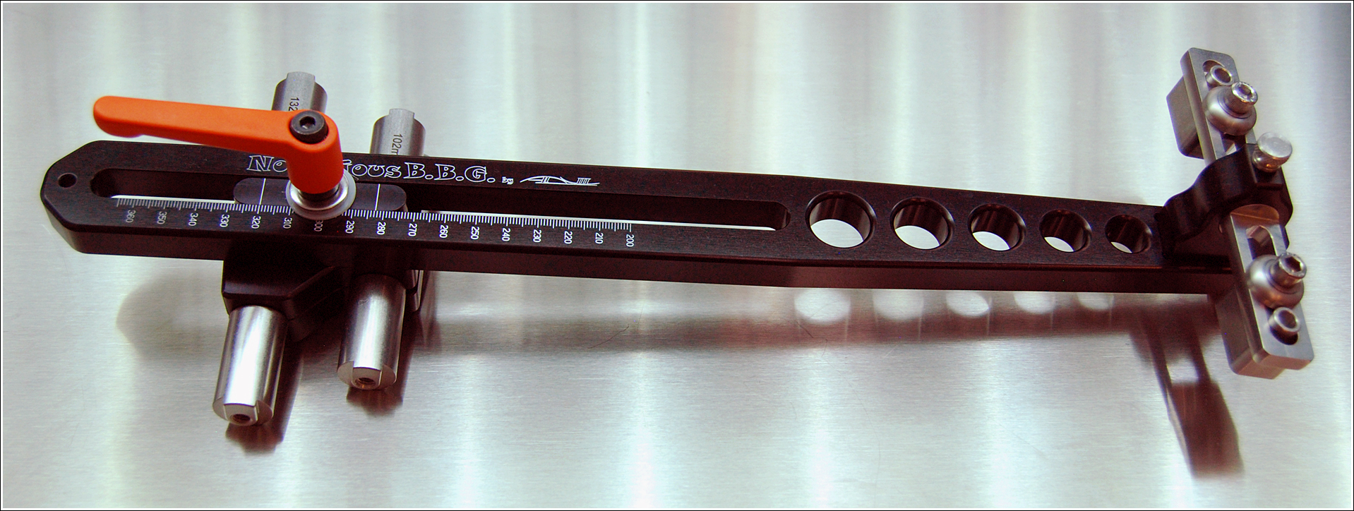
Anvil Notorious B.B.G. with F.O.G. (Finger of God) for mounting bridges and rim caliper brake bosses.
It seems that in 2013, Don prototyped but may not have released a BBG for use in fixture, either front or rear. This would have been the tool to have!
There are other tools out there, like the Sputnik Wheel Check Tool that others have copied. While it’s quite rigid and precise, the frame has to be removed from the axle holder and it’s very limited in what it does. It’s not what I want.
To get to something new and to solve my problems, I began, as I like to, with first principles and thought out what I would want a new tool to be able to do. I was able to do all of it.
- Frame fixture axle perpendicularity calibration
- Correct placement of distorted 3d prints within the frame
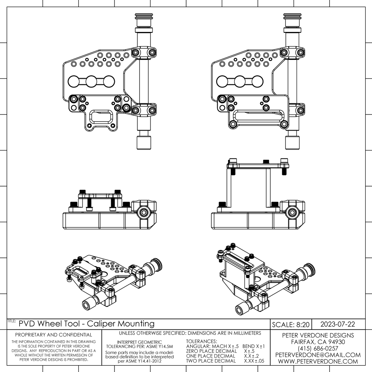
- Disc brake caliper mount fixture, flat or post mounting
- Rim caliper Brake boss fixture
- Rim Cantilever brake post fixture
- Disc Rotor Clearance reference
- Stay bridge Fixture
- Stay centering reference
- Fender center mount fixturing
- Any auxiliary fixturing or reference that relates to the wheel, stays, and yokes.
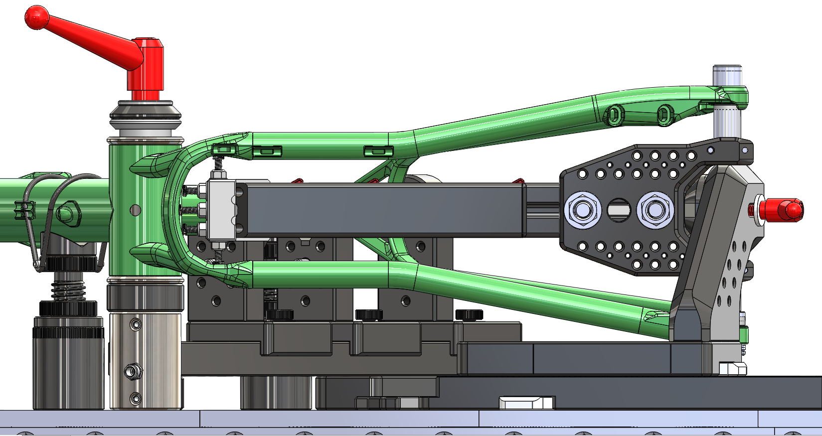
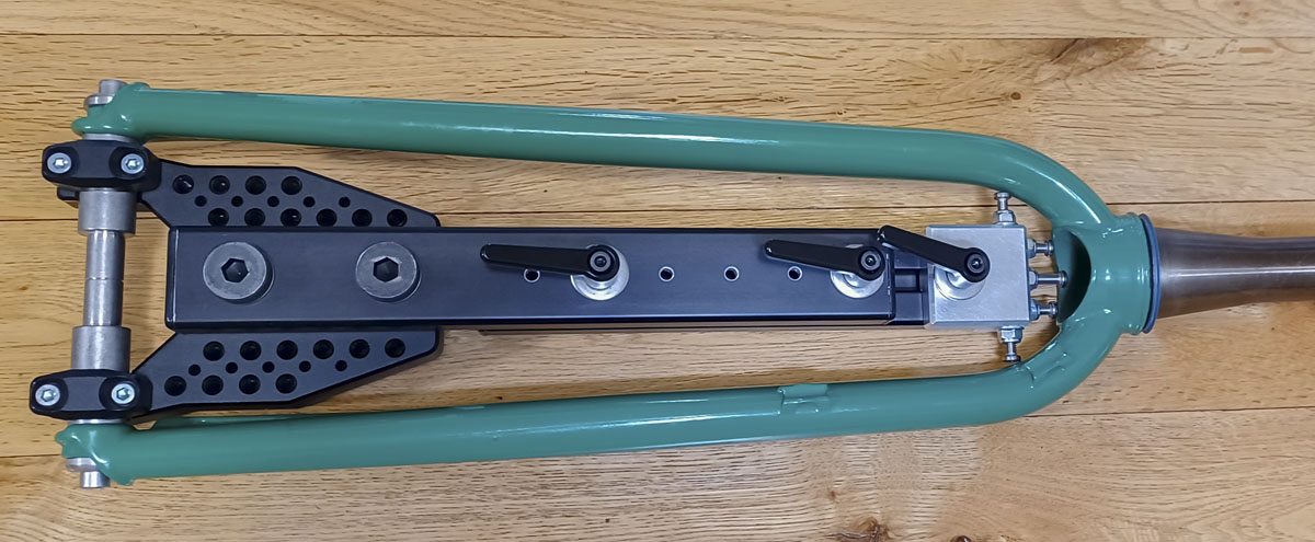
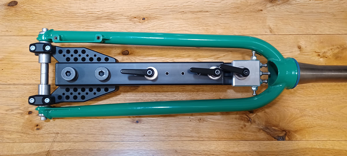
The tool can be used while the frame is mounted securely in the frame fixture or when it is completely free from it. We want the tool to be used with the frame remaining in the fixture as that increases the rigidity of all the parts as well as the locating precision. The tool can be added or removed quickly and easily while working on a frame.
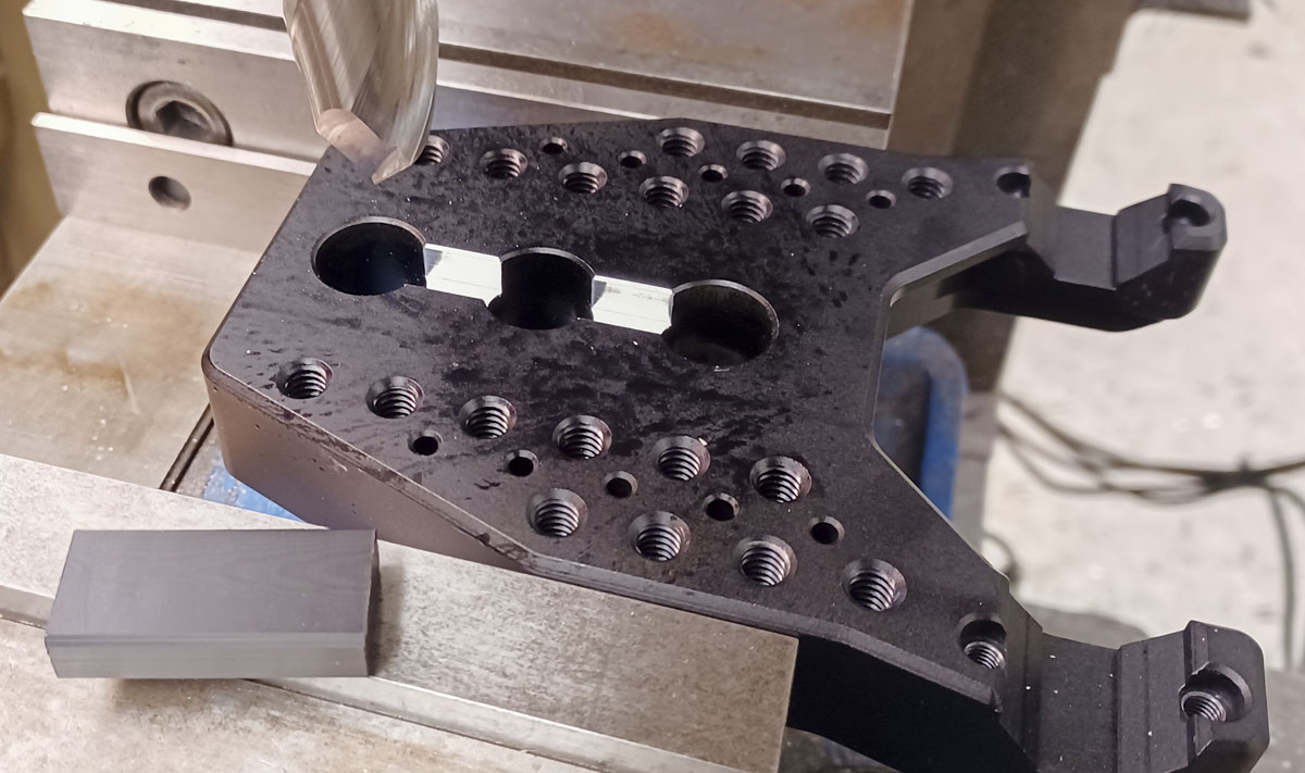
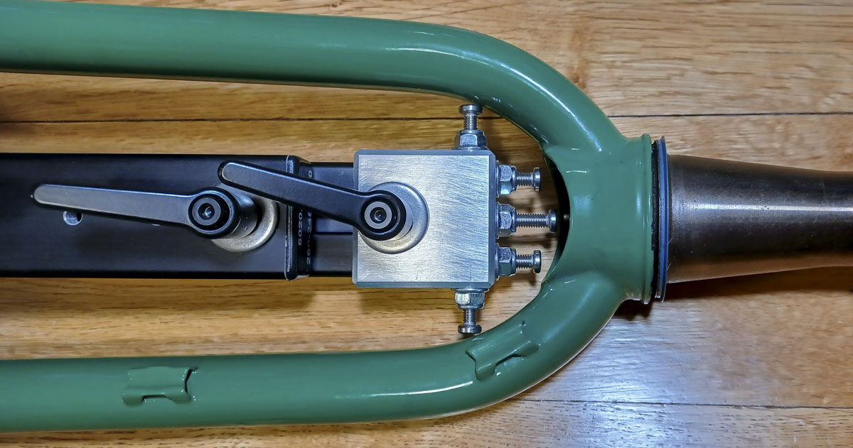
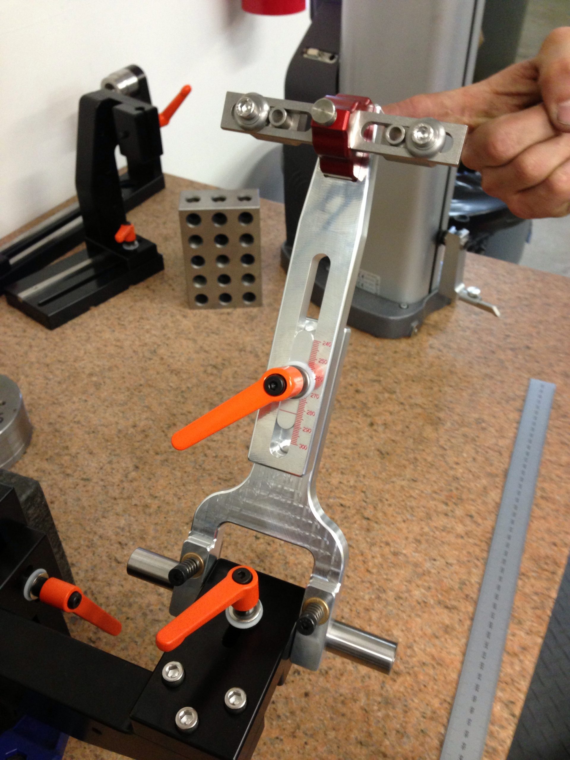
The tool is designed to work with PMW/Anvil dummy axles that have a 0.750″ diameter shaft and 2.500″ wide center relief. It will also work with the 1.375″ wide center relief that is used on front fork dummy axles, along with a small 0.531″ spacer. This is one of the most common dummy axles in the market, it’s easily sourced, and it’s what my frame fixture uses. Something close could even be made from scrap material if using this tool on it’s own.
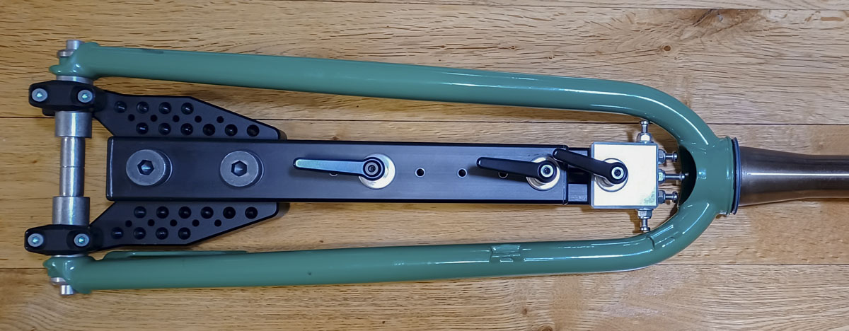
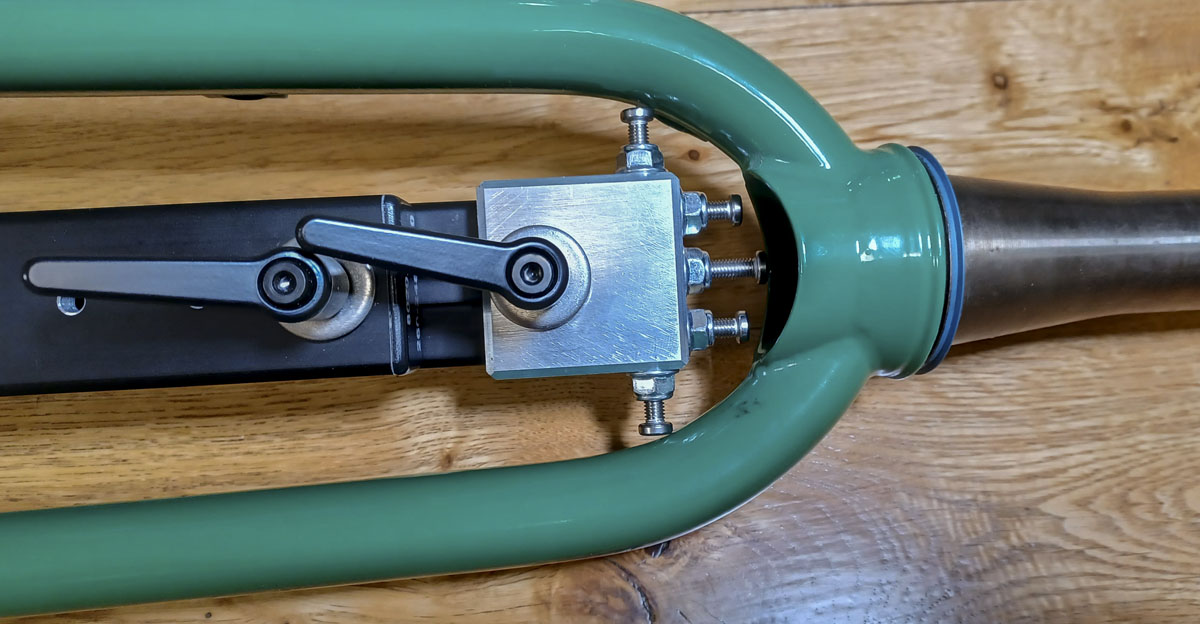
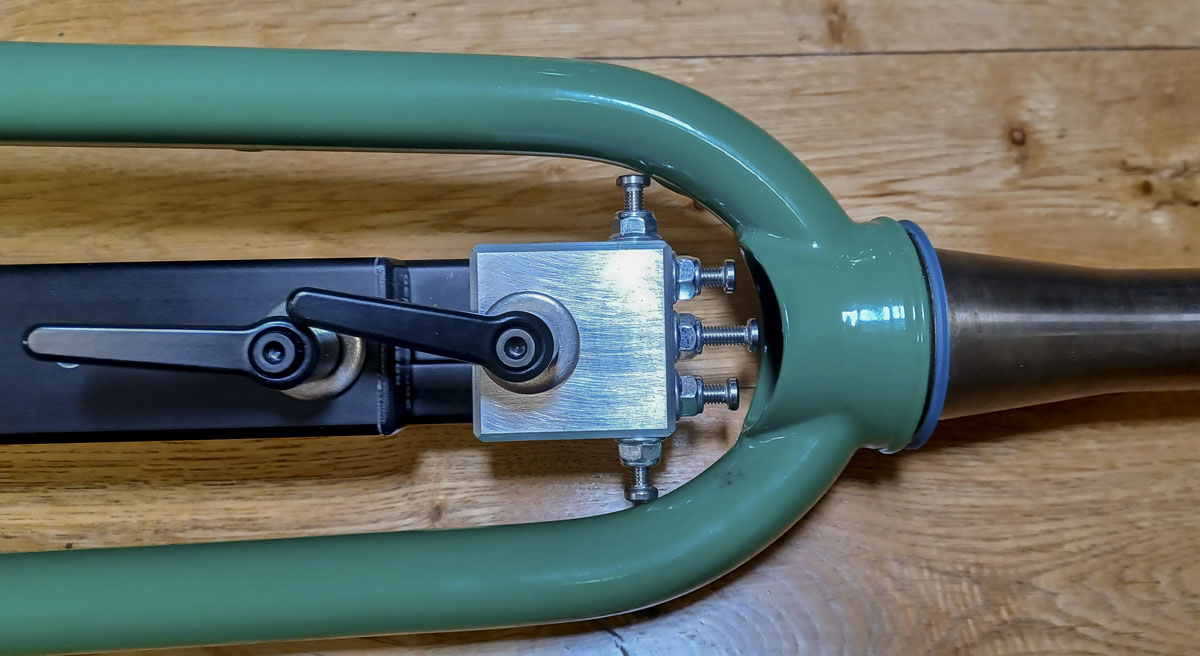
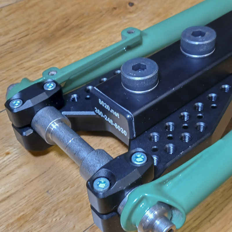
The tool is kinematically constrained by a vee-slot for radial location and a stop on one side for lateral location. It is free to rotate about the axle axis for any useful placement until it is firmly clamped fast with the binder screws. It’s a nice repeatable system.
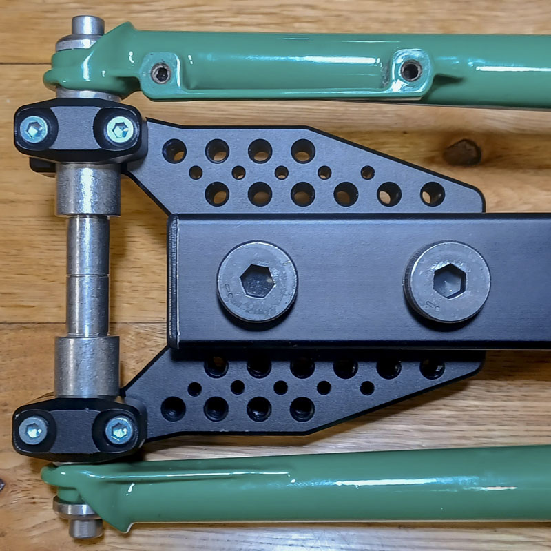
The simplicity of this design is that the top plane of the tool is coincident with the axle axis and as such, any construction built on it will be true to the normal profile of the wheel/tire at any point in the rotation. So when you are placing a seat stay bridge, you can know exactly where a radius will land, regardless of how bendy, swoopy or offset your stays are from your rear axle or other tubes, like drop stays or caliper clearance bends.
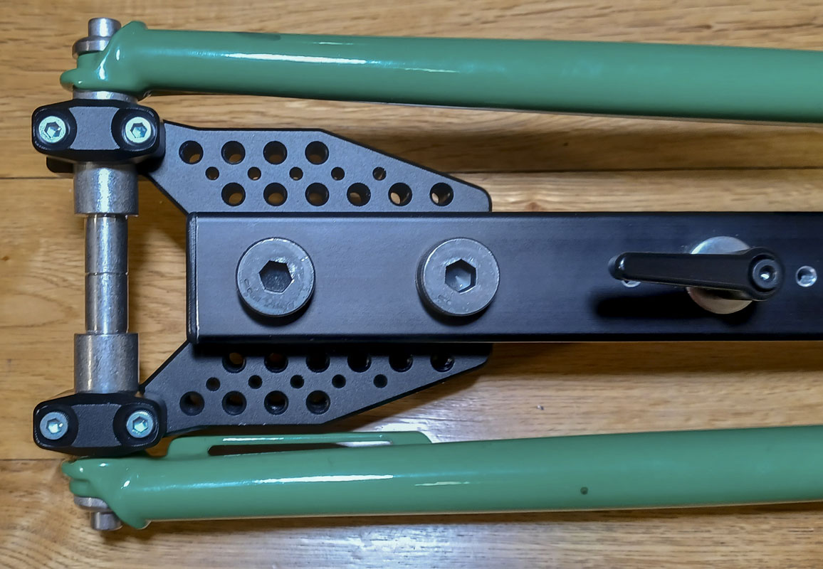
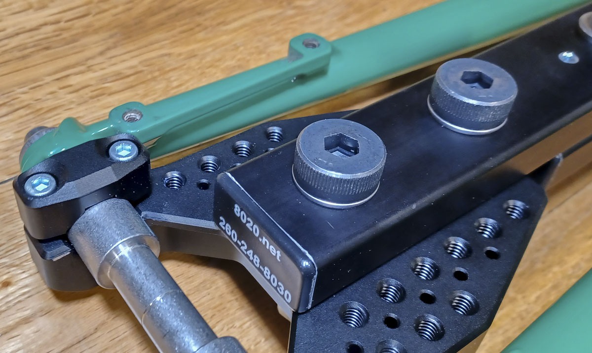
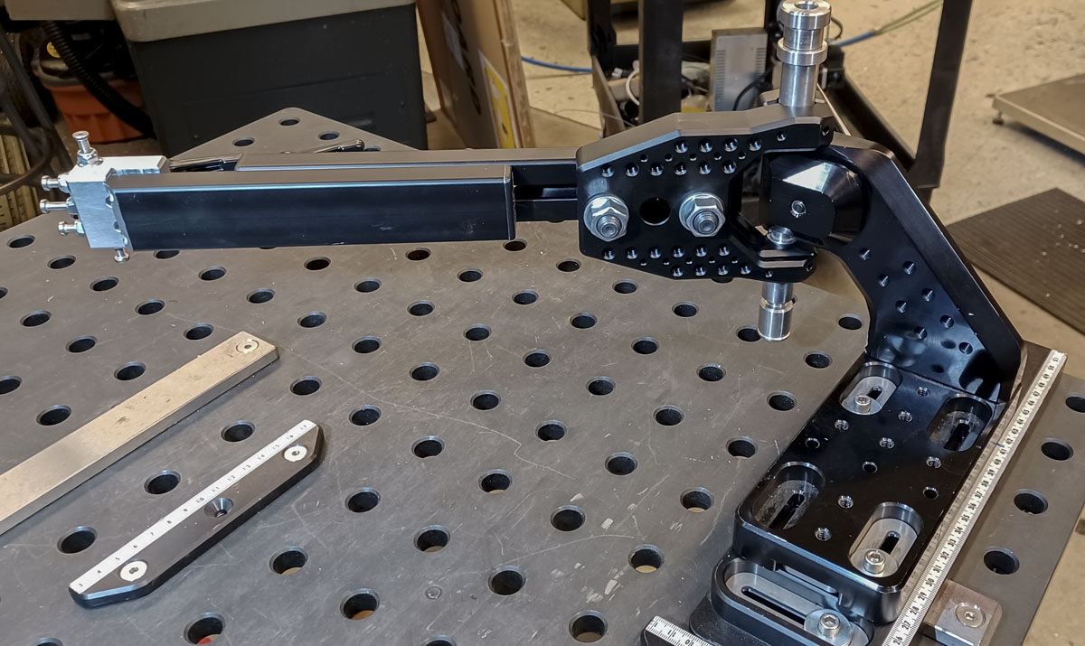
The center bar is fastened through two of three 0.625″ bores spaced 1.000″ apart. The fasteners are 0.625″ steel shoulder screws for inexpensive precision. This was chosen as it is the same 0.625″ x 2.000″ raster spacing that all of my new fixturing has been designed around as it integrates with BuildPro or Seigmund welding tables and auxiliary tooling produced by those firms. In another situation (that I haven’t conceived), the arm tooling or axle clamp plate can be mounted to weld table surfaces or towers. This provides an amazing level of flexibility for use. I can’t wait to see what comes of this!
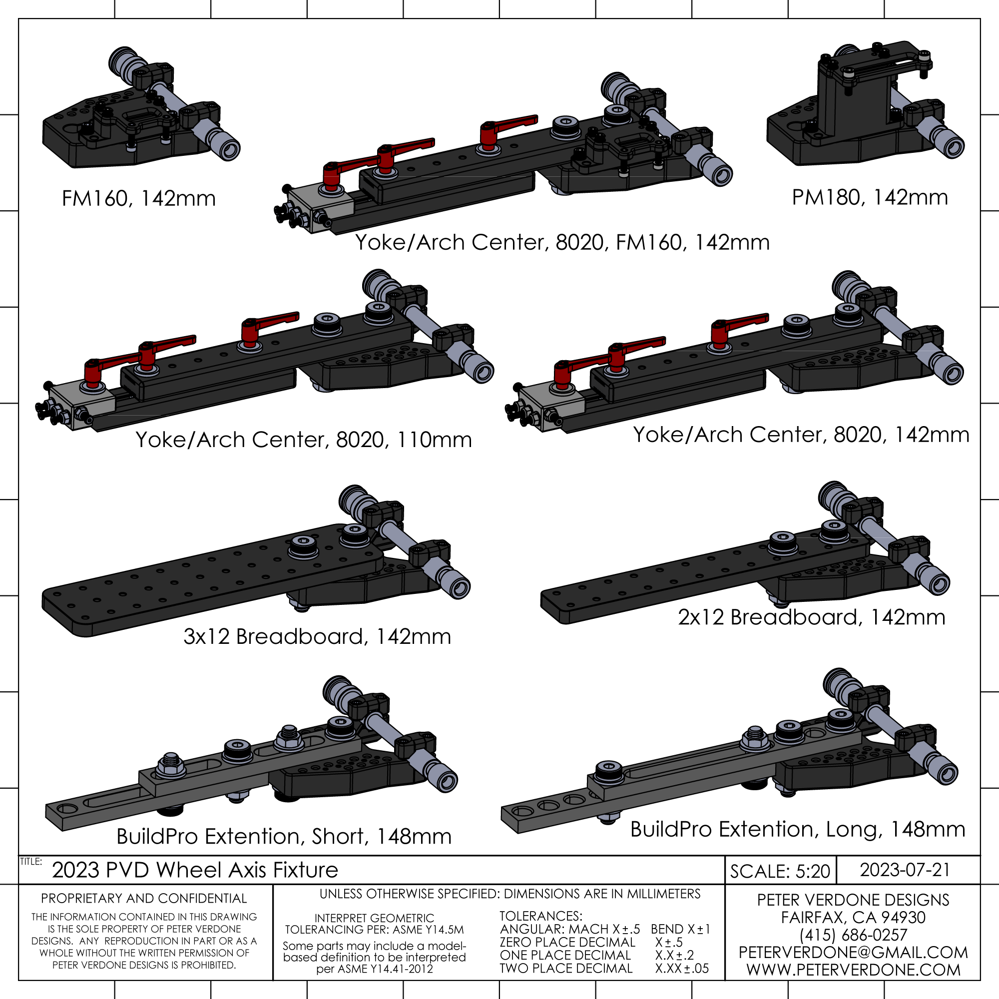
A variety of centering bars can be attached to the mounting plate:
- Paired or single BuildPro Straight Edge T50505, T50510, T50517 – steel, inexpensive, accurate, and very rigid
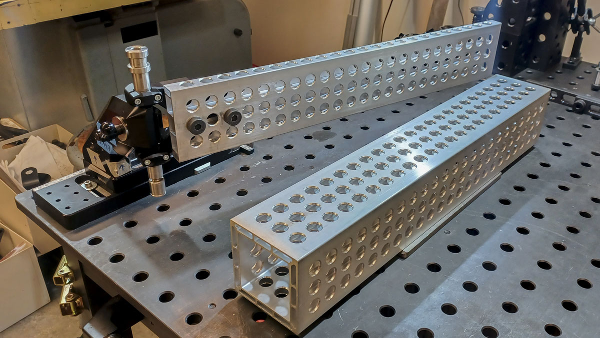
- Paired or single 8020 1575-Black-FB, 1.50” X .75″ Smooth Surface T-Slotted Profile – Single Open T-Slot – Inexpensive and highly modifiable within the t-slot framing ecosystem. This is an easy way to add very long extension bars.
- Optical breadboard, 1x, 2x, or 3x column. About 12 rows. 1/4-20 threading. Highly constructible and precise raster for any number of tooling adaptations.
So many configurations! More exist but this is a small sample.
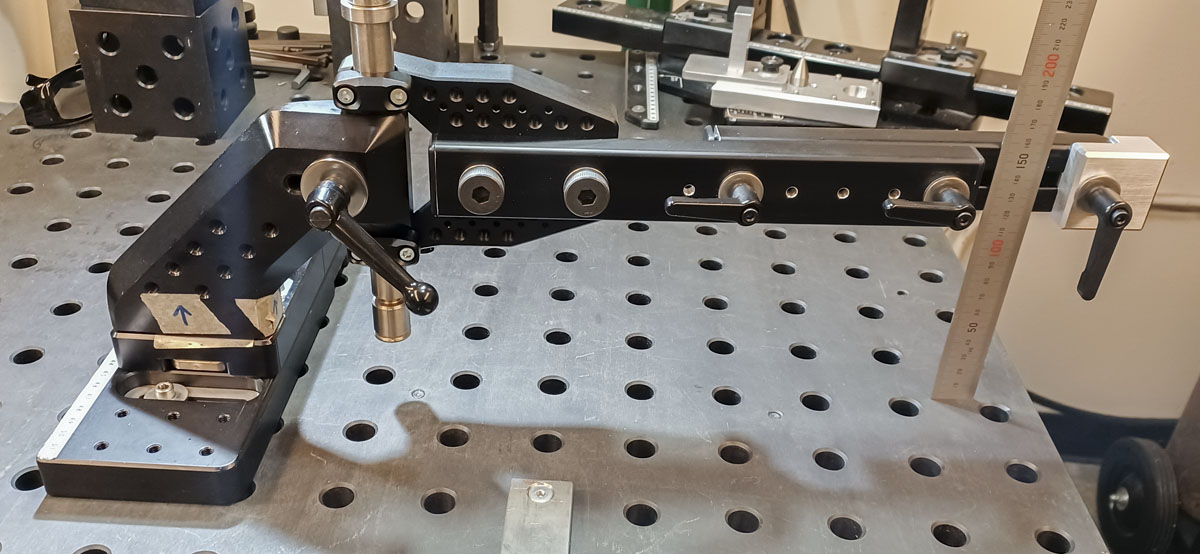
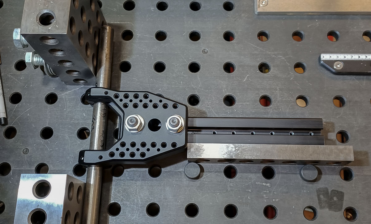
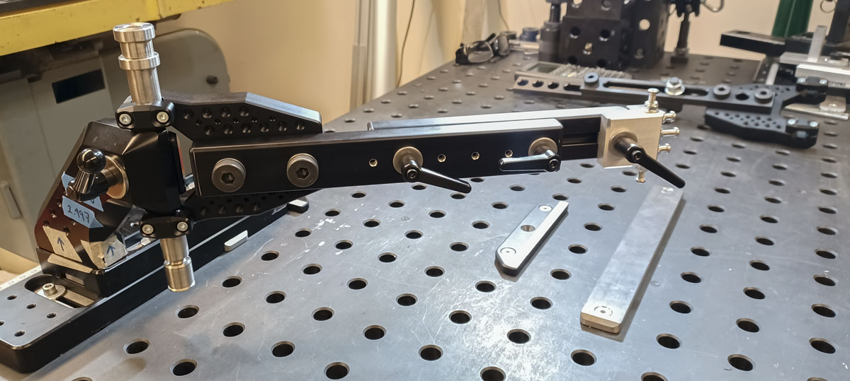
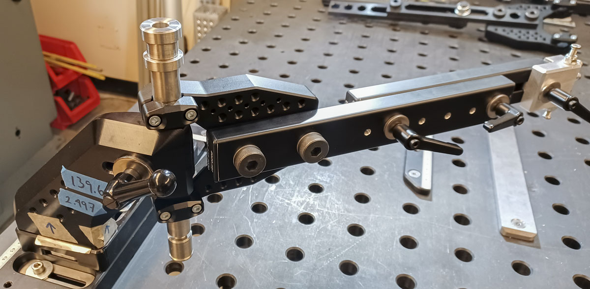
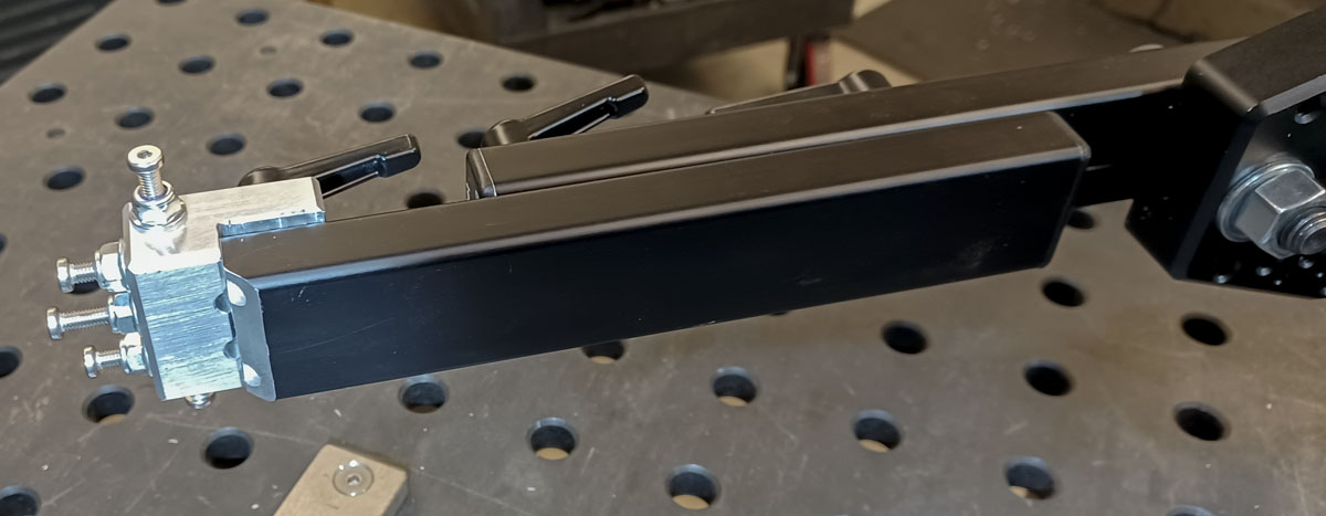
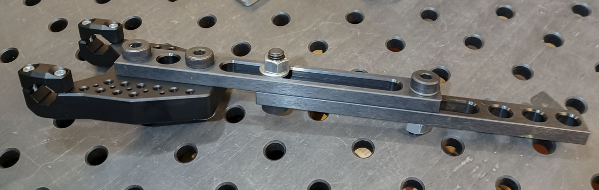
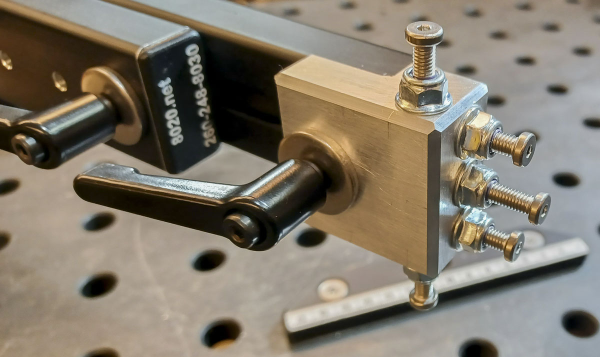
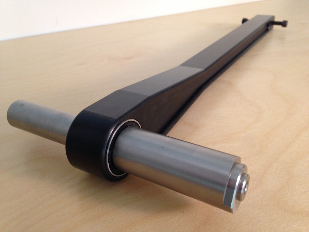
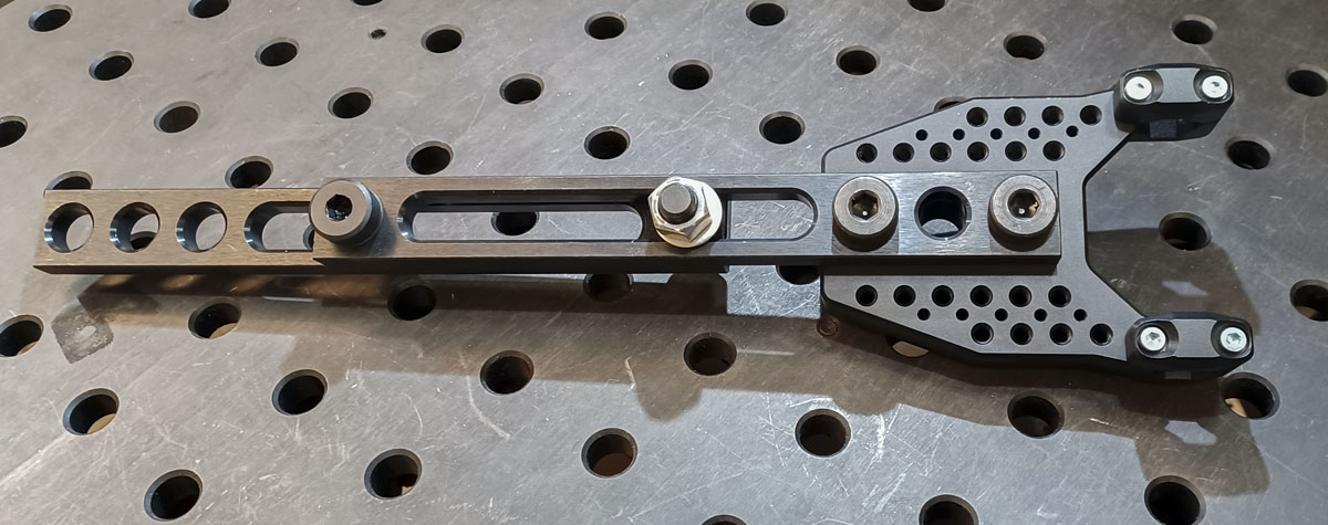
Below is a pretty trick configuration that takes advantage of BuildPro steel sliding straight edges (T50505, T50510, T50517) . It’s super rigid and can mount on either end to components in the entire BuildPro or Seigmund tooling catalog.
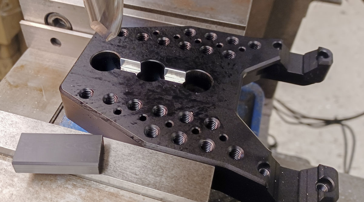
The tool includes a partial raster of 1/4″-20 threading at 1.000″ spacing. This allows optical table components designed for that raster to mate effortlessly to the plate. Ebay has tons of these components available for very little and they can do some amazing things.
The thread pattern is paired with 1/8″ pin holes give very precise location on the plate at specific distances from the axle axis and centerline. The thread holds the parts fast and the pins do the locating. Thus, any type of brake caliper mount fixturing can be developed to precisely and rigidly locate the boss directly from the main plate. Any flat mount, post mount, IS mount, Sidewinder, or independently developed system can be implemented by the designer with just a few simple fixture parts produced.
This type of tool is great for folks that are looking into getting started in framebuilding. Frame fixtures and a place to store one is expensive and a difficult proposition for many. Entry level folks will have an easier time starting with a cheep tool that allows for a lot of different rear end modifications to existing bikes. This tool, a dummy axle, a file, and a small TIG box is a short list of special tools needed to connect brake caliper mounts, fender mounts, bridges, canti bosses, etc. It could even be used for replacing dropouts and stays. I really love that this tool is totally aligned with my goal for this blog, getting others changing the world.
This tool replaces my Anvil Post Punk fixture. I now have something far better, a fully extendible construction plane for any existing or future caliper system.
One issue in the design shown here that is slightly restrictive is that hub width when working on front forks must be 110mm or greater. This was so that just one tool would be produced at this time with the widest range of use and that 100mm hub widths are effectively dead other than a few special cases. Regardless, in the future, I may make a dedicated front version with a full range and a dedicated rear with an increased interface at the dummy axle.
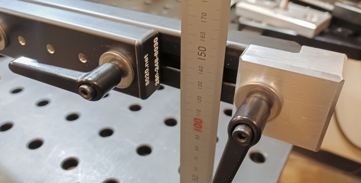
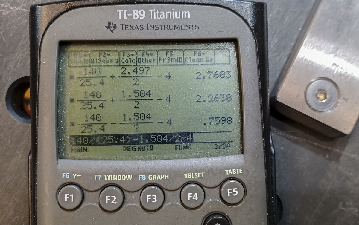
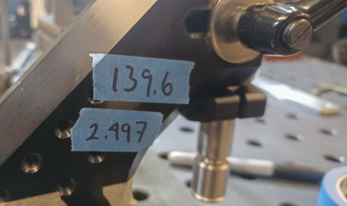
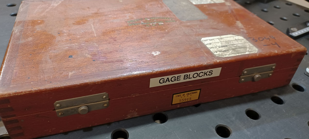
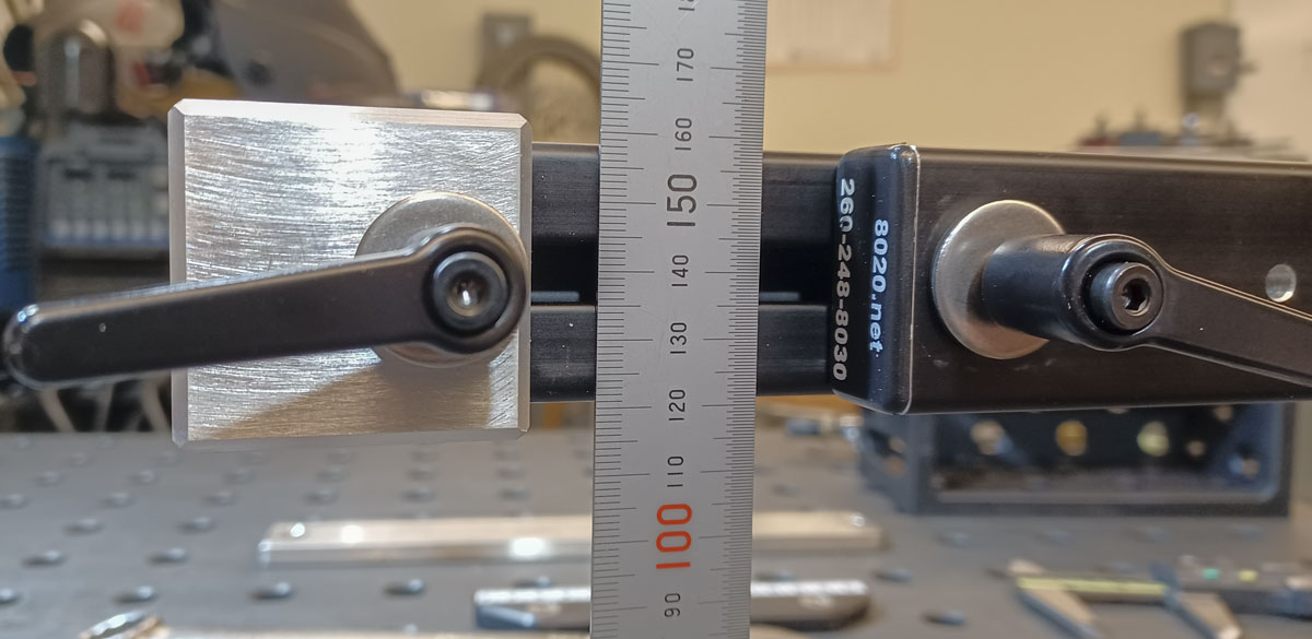
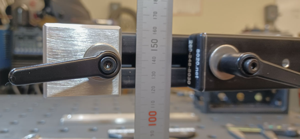
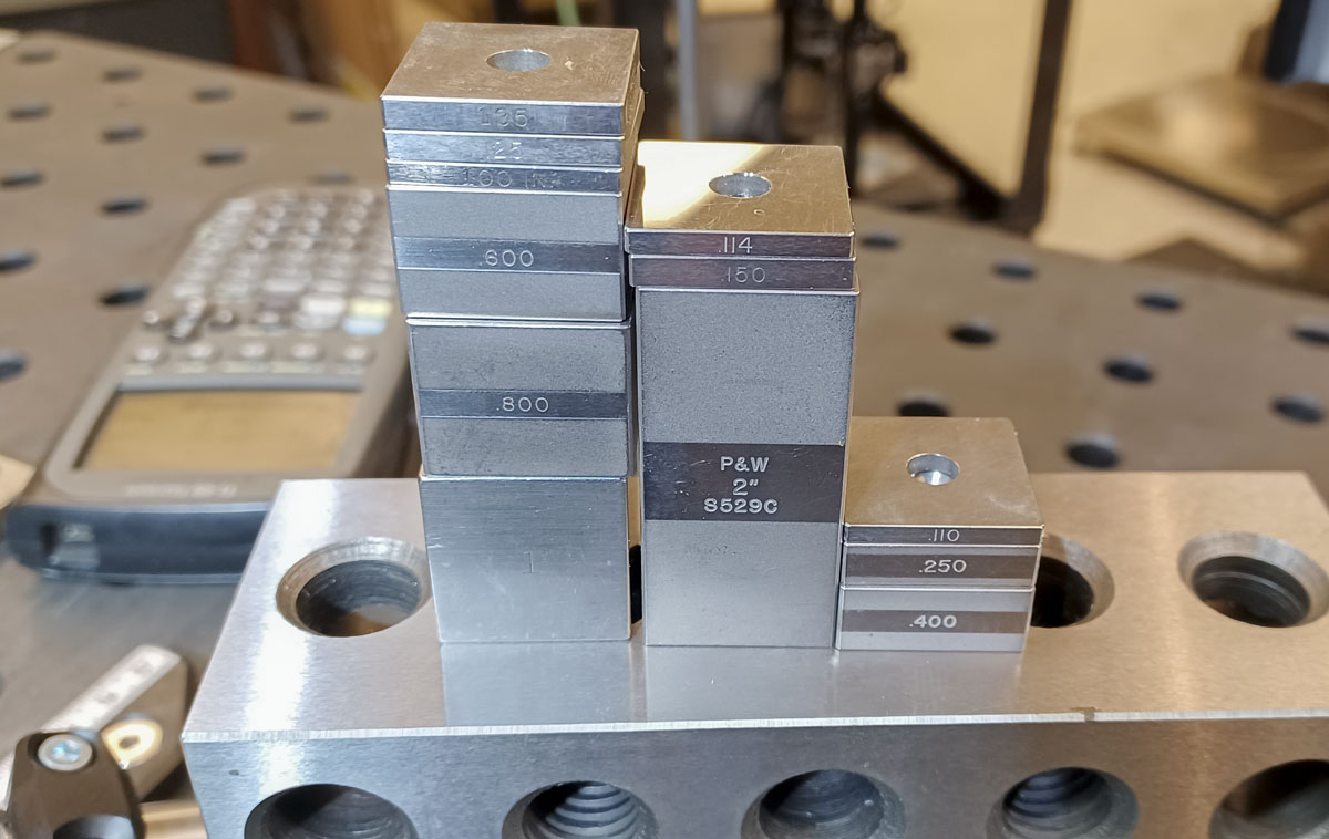
While inspecting the tool in the fixture using a complement of gauge blocks, I found that while my dummy axle holder seems to be aligned very well perpendicular to the table, but may be 0.002″ off center. I hadn’t dug so deep into this earlier and could explain some issues. I’m going to dig into this with proper shim stock on Monday.
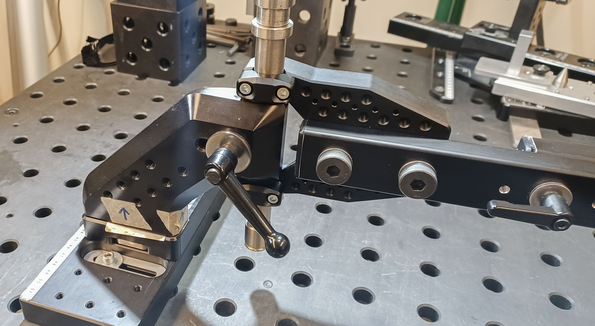
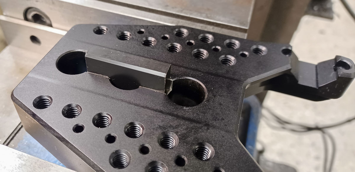
I ended up adding a 0.324″ Delrin key pressed into the plate as it proved to be the best way to align the 8020. Just a small cut and a harmless block. This was all it took to align the bar in a very accurate way.
While this is a pretty nice first draft, it’s still just a first draft. If I decide to produce a second iteration, I’m going to do some more work on making the tool quicker to place and remove on the dummy axle. I’d also add more to the integrated raster, hopefully, keeping the needed clearances.
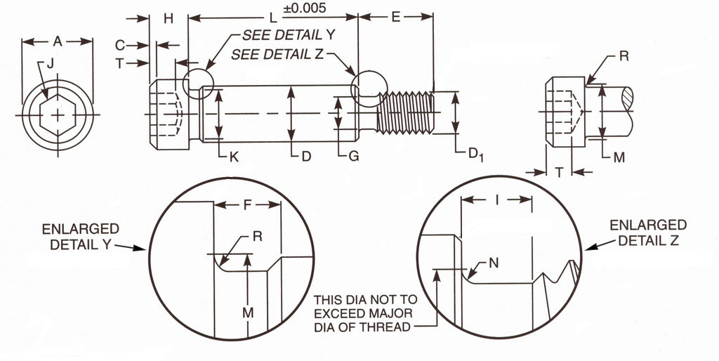
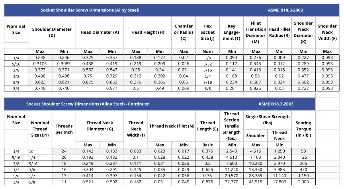
The diameter of the shoulder bolts are a bit of an issue. According to specifications, the diameter of a 5/8″ shoulder bolt should be 0.621″-0.623″ and some cheaper types go slightly over that. Many fixturing weld tables uses hole bores in the 0.627″-0.630″ (IIRC). This creates some problems when using closely spaced holes for ‘perfect’ alignment, even if the hole bores are cut dead on 0.625″. I may produce a couple of oversized and stepped pins to help take up this slop in adverse cases of use.
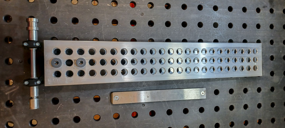
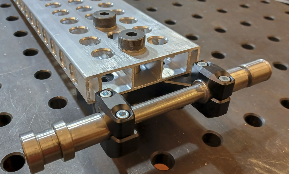
Going big or need to do something wild? How about this configuration using Siegmund aluminum profiles: