Updated some parts 04/2026: https://www.peterverdone.com/basic-upgrades-for-samantha/
It’s time for a full update on the Samantha frame fixture. It’s wise to capture the state of the art periodically. Some of this will be a repeat of past posts but this is a single page, with all of the updates included, ready for sharing.
The Samantha bicycle frame fixture has grown out of my previous work on the Cyberdyne, SKYNET, and WOPR fixtures, as well as several generations of specialized handlebar and sub-assembly fixtures. Review the documentation on these systems to fully understand where the Samantha fixture originated.
Each of these systems were constructed to serve one goal:
An adjustable fixture for doing serious R&D level work to produce modern bicycle frame, fork, and handlebar designs.
Commercially available frame fixtures are not optimized for progressive nor rear suspension bicycle frame designs. The Cyberdyne fixture was initially constructed in 2020 in response to having exceeded the length capacity of an Anvil Journeyman fixture. More, to construct a rear suspension frame, very precise placement of pivots within the frame become absolutely crucial. A traditional beam system can’t do this. Raster type fixtures do provide this precision in placement as well as extendibility of scale. Downhill racing bikes, tandems, and tall bikes are trivial constructions with these tools.
In recent years, one-off extruder printed tooling components have become the method for beginners to produce their first frames. These are easily made on a home printer and are sufficient for basic work holding. Even if one is to continue with this method, I HIGHLY recommend having a fixture table to work from. This will add both rigidity, accuracy, and extendibility. This will become clear in the information below.
I was not lucky enough to have gotten started in this new ‘additive’ generation. Still, there comes a point where an increase in precision and rigidity are required to work at higher levels. Due to the cost in making that happen, it helps to have a truly adjustable metal fixture. Once this is done, more work can go into bicycle designs. There really is no limit to the adjustment available on Samantha: the length, height, angles, or width (with some tooling) that this fixture can accomplish are boundless. If you want a 5° head angle, a -60° seat angle, and a 4,000mm rear center – you can have it, but you may need several tables.
Fundamentally, this fixture is building from a raster on a plane. An extremely rigid surface with discrete points in precise locations is a problem already solved and can be leveraged. This is an obvious choice for aerospace fabricators that are familiar with these precision fixture tables in their shop. For one more familiar with scientific environments, optical breadboard with 1/4-20 or M6 thread holes could be a reasonable substitute.
These tables can be as small as 2’x4′ and grow to 5’x10′. They can be ganged together to produce almost limitless work areas. BuildPro and Siegmund have extensive catalogs of accessories and tools that interface with these systems. These are expensive, costing $2,000-$4,000 to get started.
At first blush, you might think that these lie outside of a small fabricator’s budget but it turns out that using one of these is cheaper and produces far more value than a stand alone frame fixture. A crucial understanding is that while an investment in a table like this is sizable, it contributes significant value in a workshop. Specifically with regard to bicycle production, frame alignment can be done on the table eliminating the need for space and capital investments for such a tool. I’ve used it for fork and handlebar fabrication. More, having a fabrication table that makes any other welded workshop project into a trivial affair is a huge asset.
In a pinch, a Certiflat ProTop – 36″x48″ table top could be used. This costs $650.12 ($550.13+$99.99 shipping, as of 2025-11-01). With some care and attention, this could work fine for someone starting out and minimizes the effort of the lowest cost option. At 3/16″ thick, extra care should be taken to produce a flat and rigid end product.
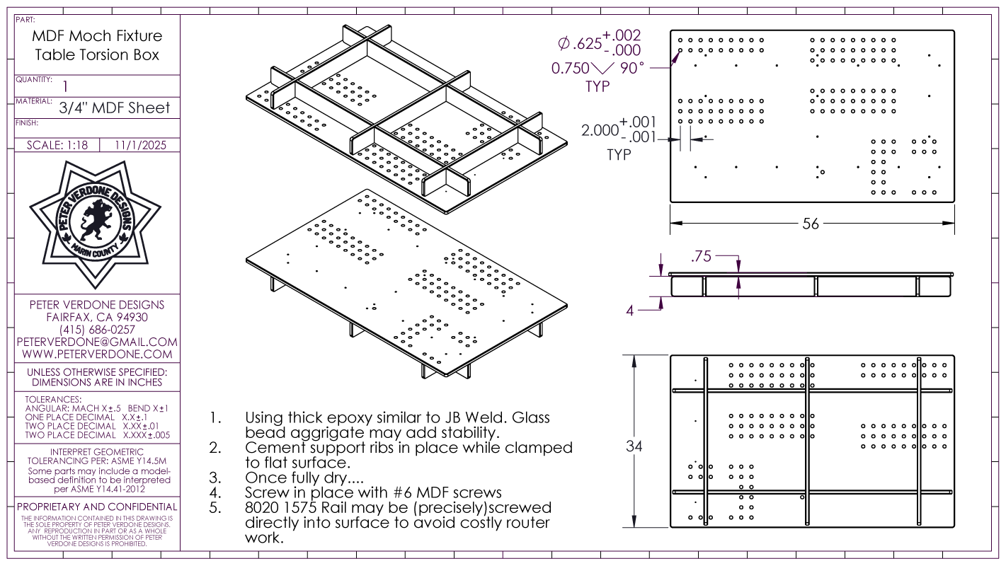
If one simply doesn’t have the funds or facilities to procure such a table, a torsion box can be made from MDF obtained at a local lumber supply. Because of the wildly extendable nature of the fixture design, rudimentary surfaces may be employed until such a time they can be upgraded. While it is preferred that the dog holes be cut on a CNC router, rails may screwed directly to the MDF provided that great care is taken for precise placement.
Flatness and level of these tables is crucial to getting the most from them. For this reason it is important to place the table on leveling feet and not on casters. I have a small 48×30″ RhinoCart in my workshop. It’s a simple 16mm steel plate mounted to a rudimentary frame. Sadly, this has an effect on the flatness of the top surface. To calibrate the flatness to within 0.002″ over the entire surface, I mapped out a system of adjustment screws that could push or pull on the surface. Some of the RhinoCart models now come with such a system in place.

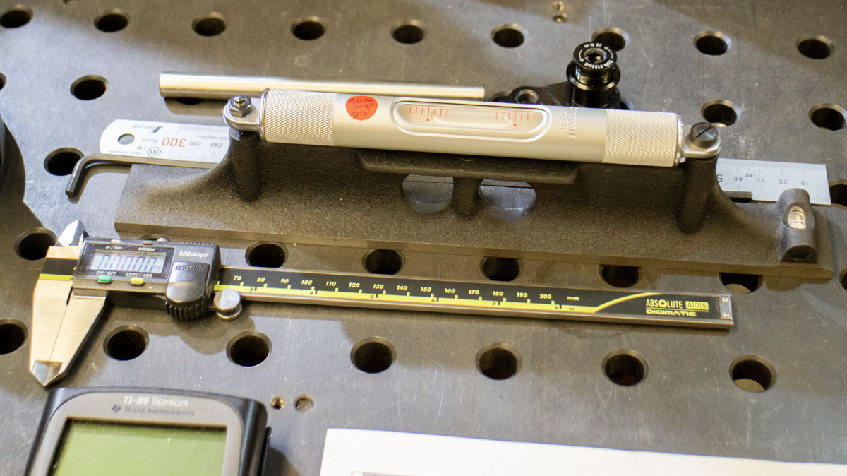
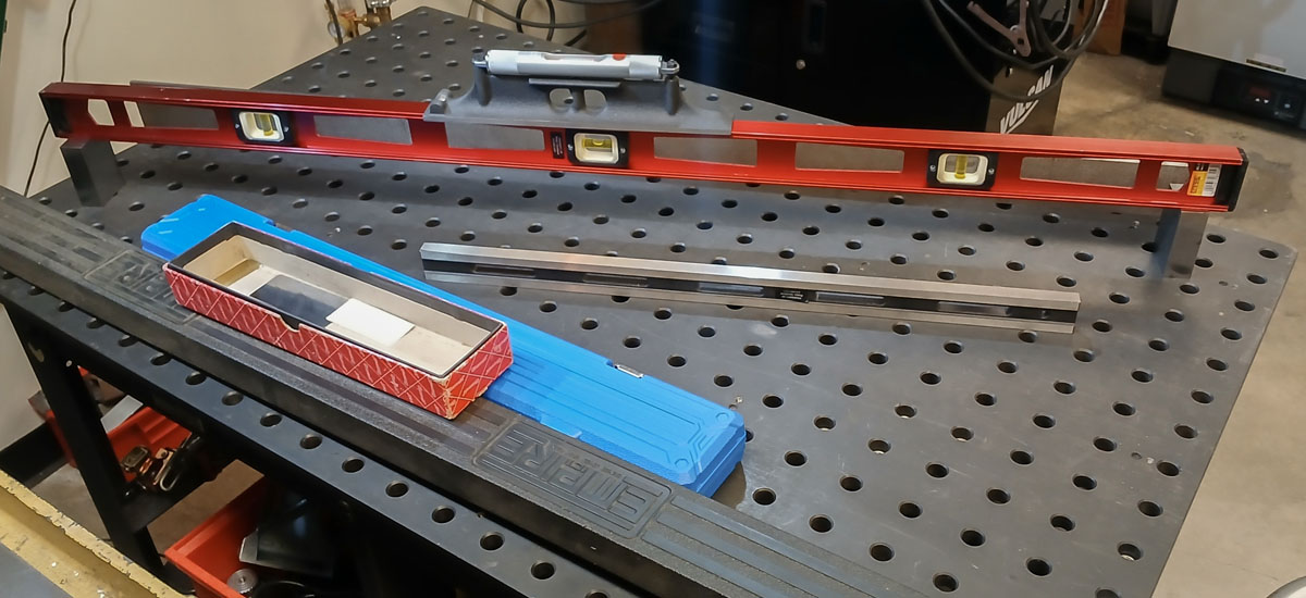
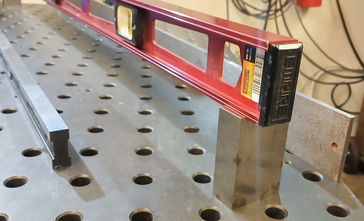
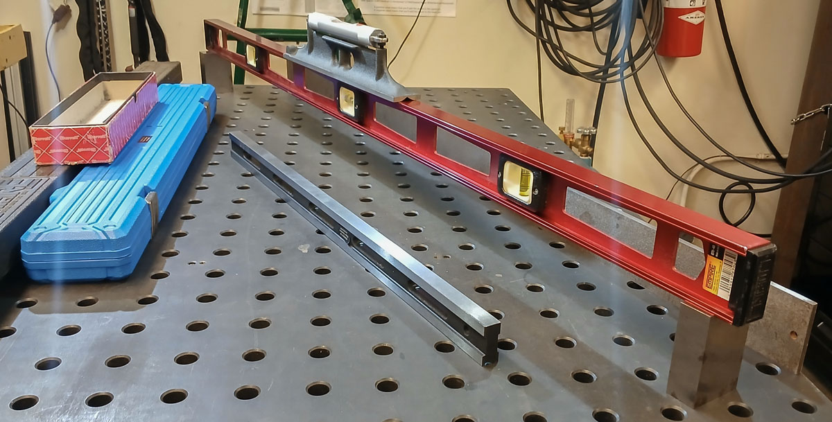
Calibration of the surface is best done placing a quality machinist’s level on a long straight edge standing on 123 blocks. This allows a sample of points to be tested across the table. The straight edge that I would like to own, a Suburban Tool SE-48-CI cast iron straight edge (or longer), starts as a $1719 proposition and that’s not in the budget right now. I have a thin 48″ steel straight edge and a short thicker steel 24″ straight edge. In a bind, I found that the old aluminum i-beam Empire 870-48 48″ level that I had was extremely straight and parallel. For now, I’m using that to work my way around the table and adjusting points to level before using feeler gauges to do very fine tuning. Maybe one day I’ll have a nice autocollimator in the shop to use.

The majority of components that make up the system are small sections of BuildPro fixture plate, 8020 1575 t-slot rail, and shoulder bolts. A few specially machined parts have improved the precision and rigidity of the sliding parts and tube support. What this means is that much of the expense and effort to construct this fixture can be extended to a myriad of other tooling scenarios that are bike related or not. Legos.
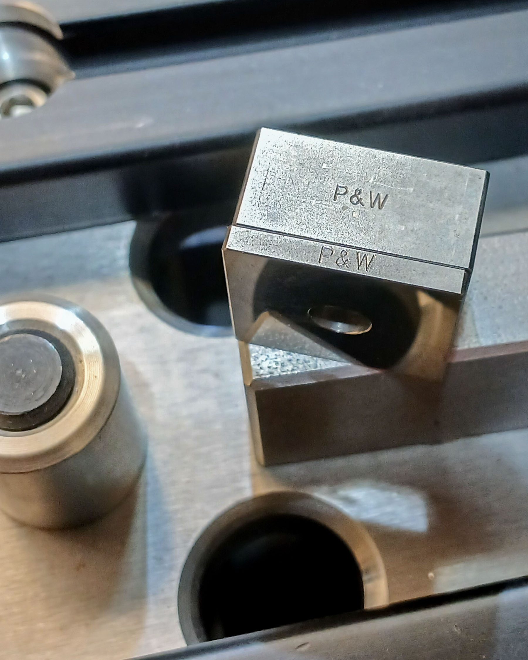
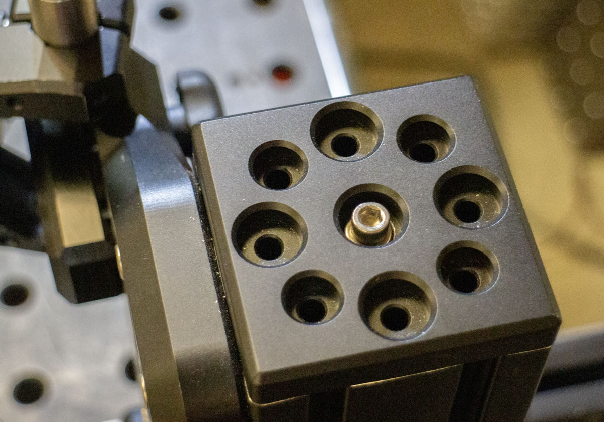
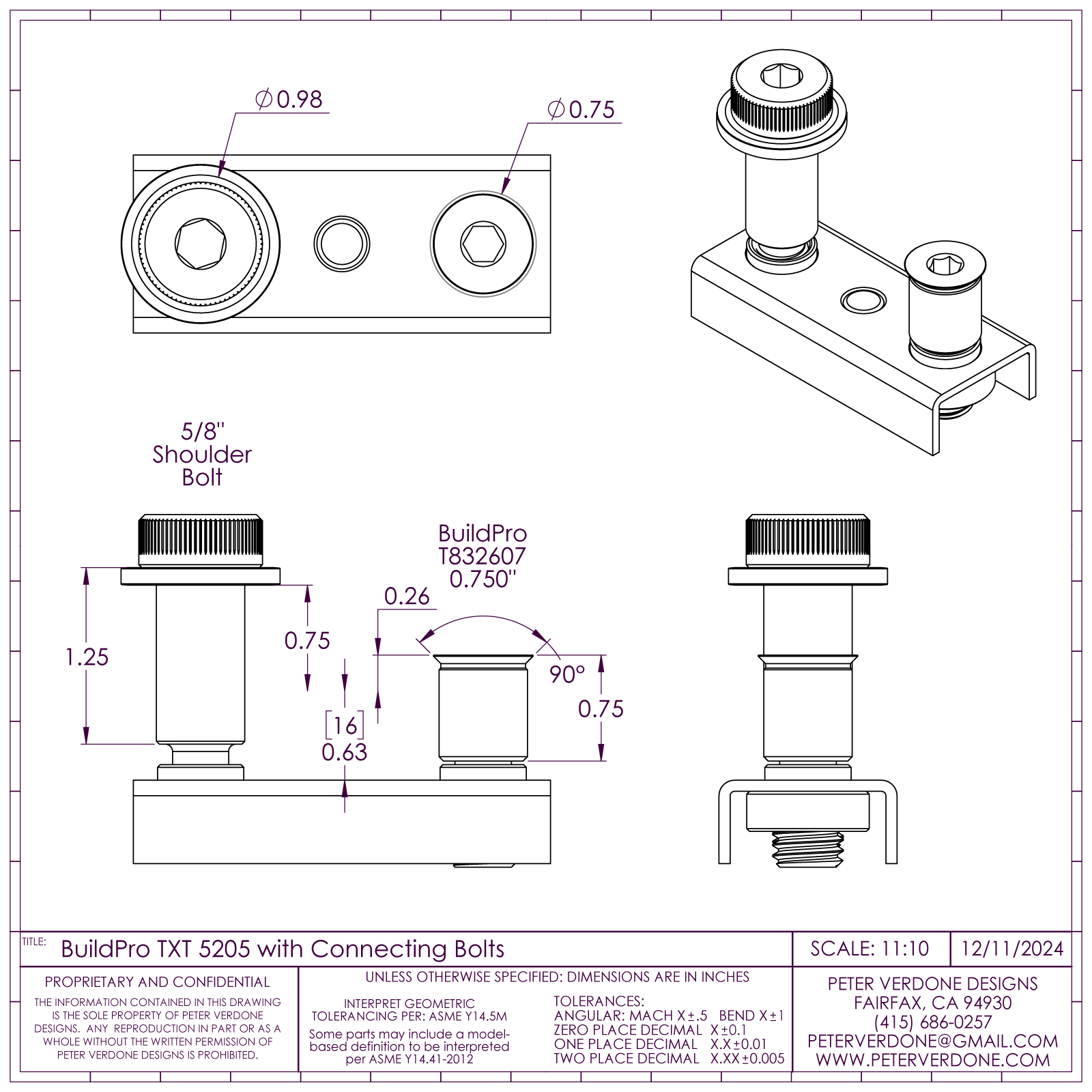
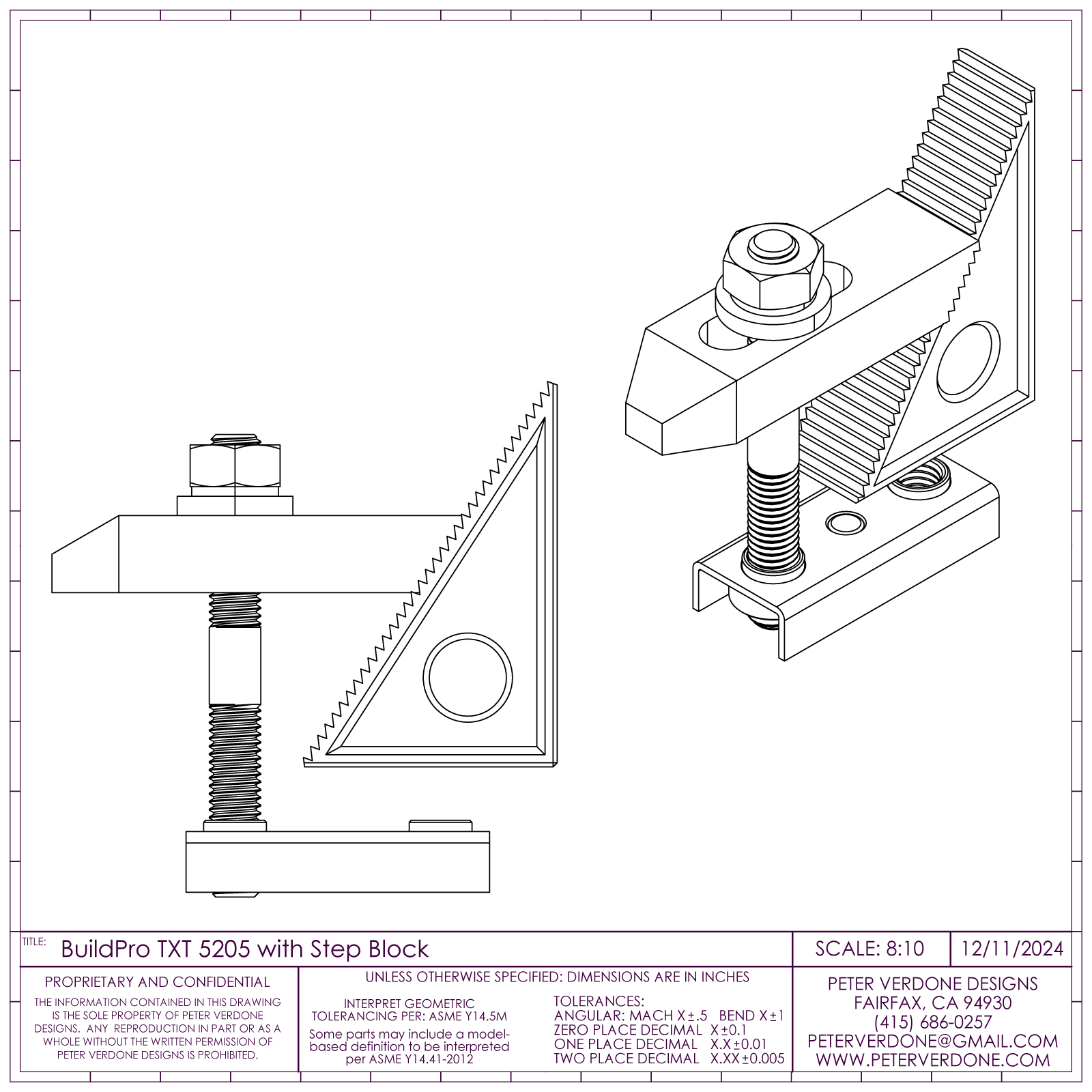
Very low cost shoulder bolts and magnetic thread plates do significant work holding parts of the system together. The real magic here is that 5/8″ shoulder screws have 1/2-13 threads. BuildPro sells 90 degree countersunk “Flush Mount” shoulder screws: 0.75″ (T832607), 0.875″ (T832608), 1.00″ (T832610), 1.25″ (T832612). These simple commodity fasteners allow for all kinds of uses around the table.
The magnetic thread plates are BuildPro TXT5205 & TXT5305. Sometimes, a 90 degree countersunk shoulder screw is needed, like when mounting 8020 rail. We use threaded inserts from there to step down to the smaller threads. There are many EZ-LOC inserts available for the 1/2-13 thread. HERE is a list. Changing them around is quick and easy.
Since the native thread on the magnetic plate that I have for the 5/8″ shoulder bolts is 1/2-13, most common milling machine hold down clamps can also be used. Sets of these are very low cost, wildly rigid, and extremely useful. Gibraltar & TE-CO Tooling has all kinds of options for this. Hold down clamp parts are available at McMaster-Carr.
The bike lays on the table over the raster with the Y-axis normal to earth. This makes it trivial to measure any point in space space relative to the frame. This makes it easy to have pivots and such accurately land where they need be for any shape frame. Some would align the head tube axis normal to the raster but this is a mistake. That means the zero and raster must change for every frame. Special tooling for suspension would need to be constructed for every frame. More, in the real world, at the table and fitting tubes, there are times when a tube is cut just slightly short. In that case, the head tube or rear axle can slide to make up for it. A trivial shift. This will be a very slight change in the front or rear center but no other parameter. An aligned head axis means that everything would change.
In this system, a spreadsheet calculator is used to place the components for fixturing a bicycle frame. This is most often produced with MS Excel but many other programs or online tools may be employed.
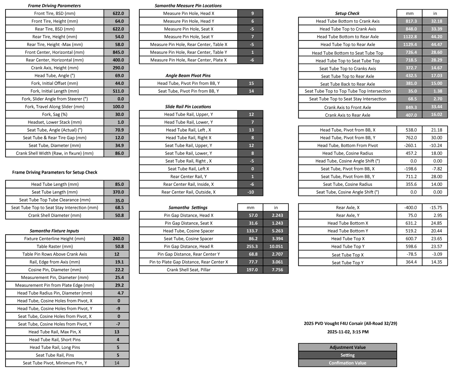
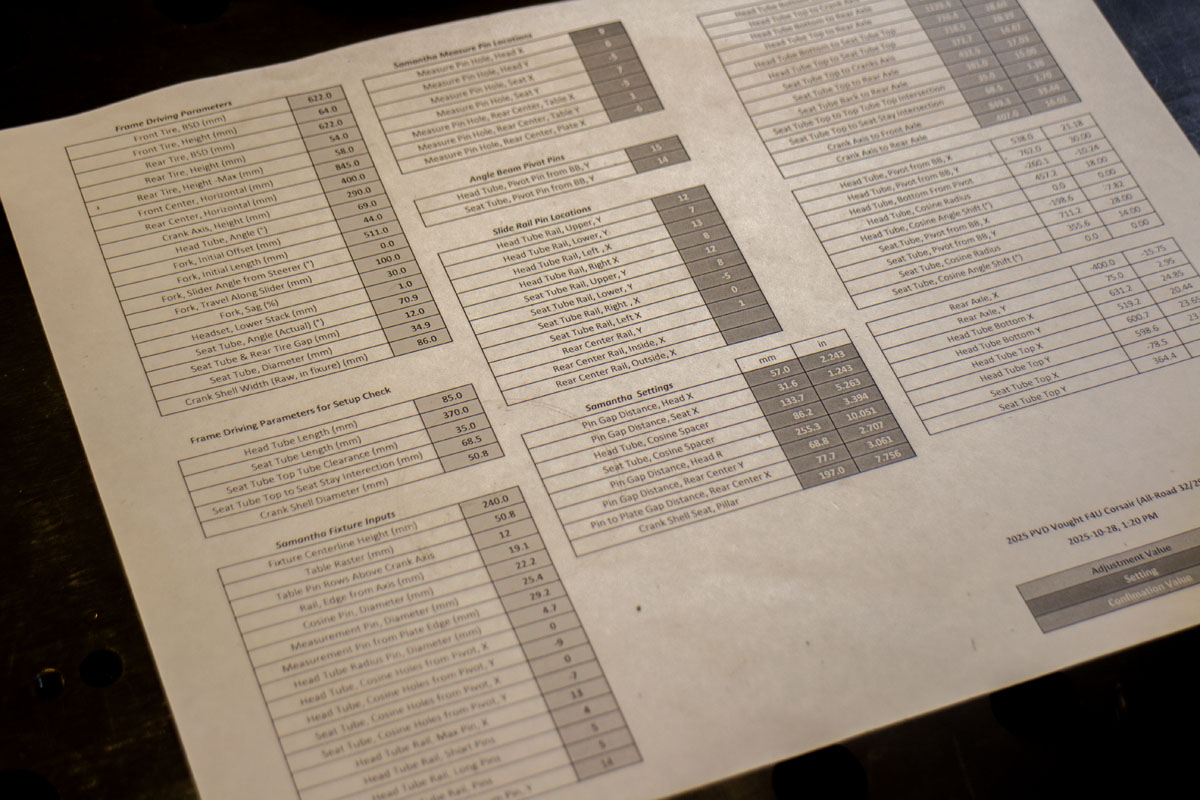
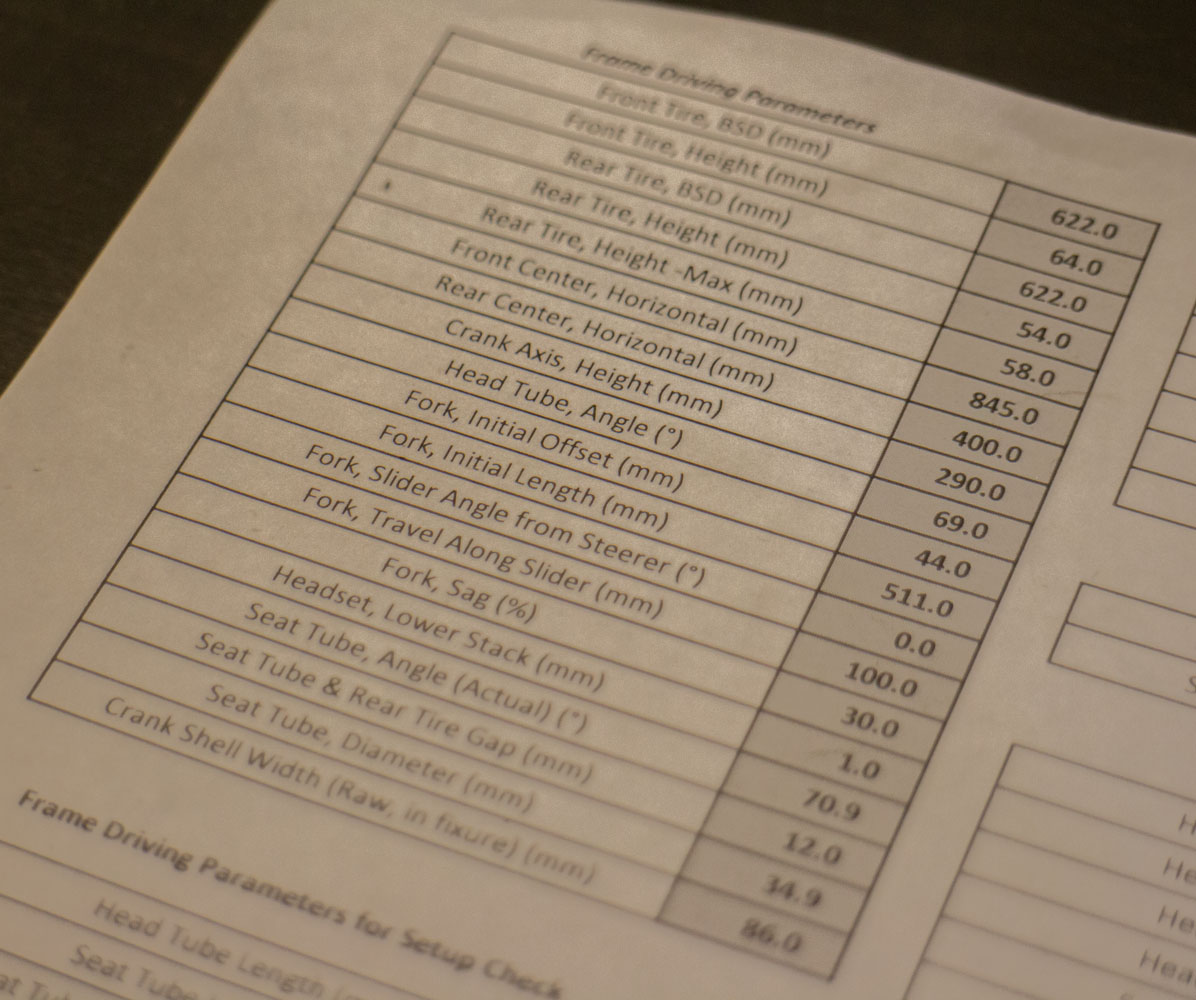
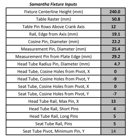
The frame’s driving parameters are first entered. Everything about a bike frame stems from here. We need to know the specific shape this bike frame will take. Considerable work has been done in the last several decades to use the most elegant and meaningful dimensions possible.
19 driving dimensions are required for the setting of the fixture to produce the frame with 5 more needed for validation dimension calculations. Another designer may come up with a different set of driving parameters. I’d be happy to review a set that makes more sense than this…but I doubt that is going to happen.
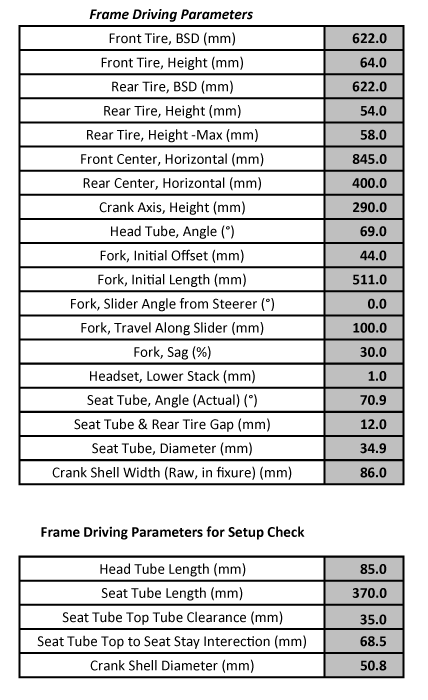
The calculations need more parameters that describe choices made during construction and setup of the system. These are items like the center plane height, raster of the table, etc. Some of these may seem odd but are explained by the conditional calculations (if/then) that have to be used due to the stepovers when using a raster. The ability to modify the fixture and change any of these dimensions gives the user full flexibility in components and structure. Again, this is an extremely modular and extendable system.
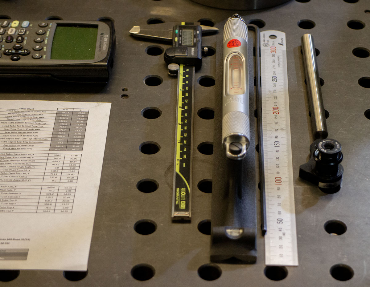
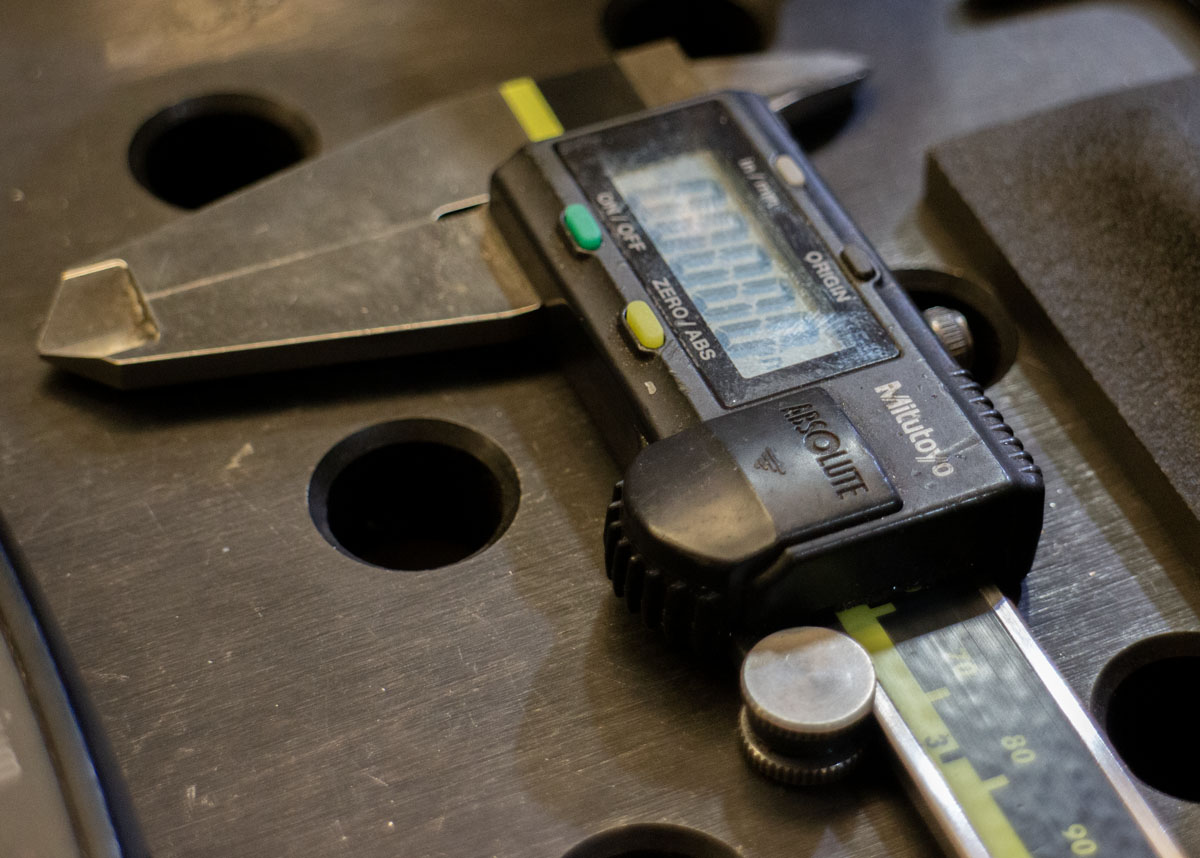
Interestingly, it doesn’t matter whether the table raster is 2.0″ x 2.0″ or 50mm x 50mm, or the size of its component parts. The math resolves that so that either imperial or metric dial/digital calipers may be used to set the fixture. I prefer to work with metric units in bike design but some measures are often easiest in the shop with imperial blocks. I can mix and match.
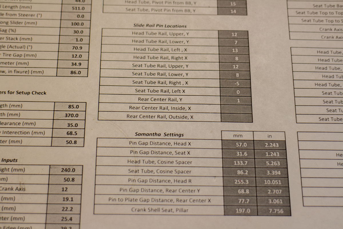
With all of the driving parameters for the frame and fixture entered, the system returns the driven settings. Results for the placement of the measurement pins and the rails are produced.
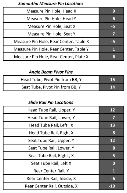
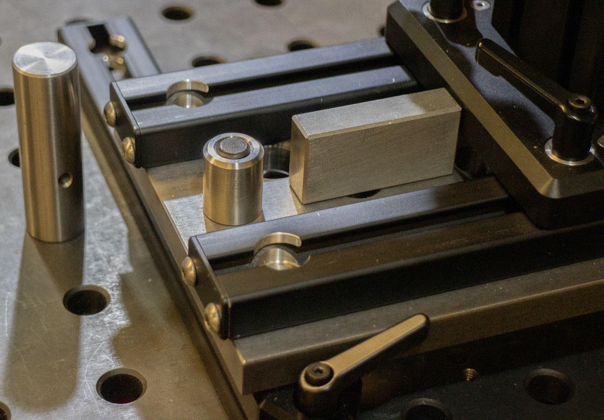
Measurement pins are extremely strong and precise. They form waypoints on the table from which to reference.
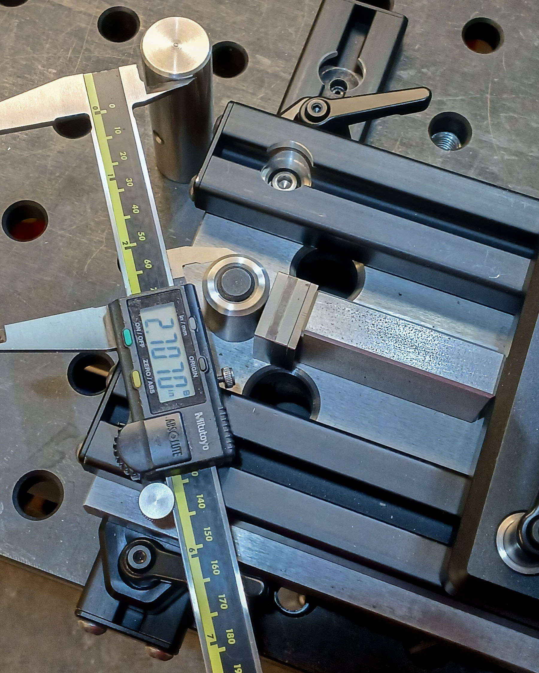
With the fixture now in place on the table it can be set very precisely to produce the frame. These settings are all easily accomplished within 0.001″ using common shop calipers or gauge blocks. You’ll notice that there are no scales or registrations anywhere on the fixture as they are unnecessary and would actually reduce the precision in setting.
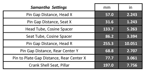
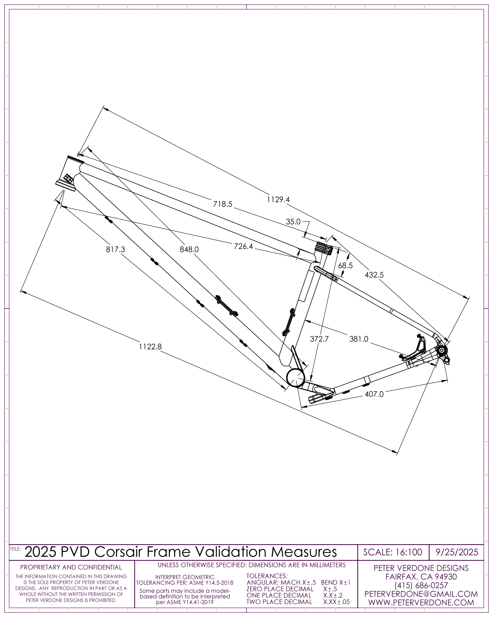
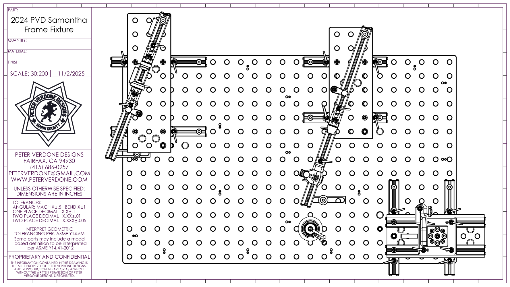
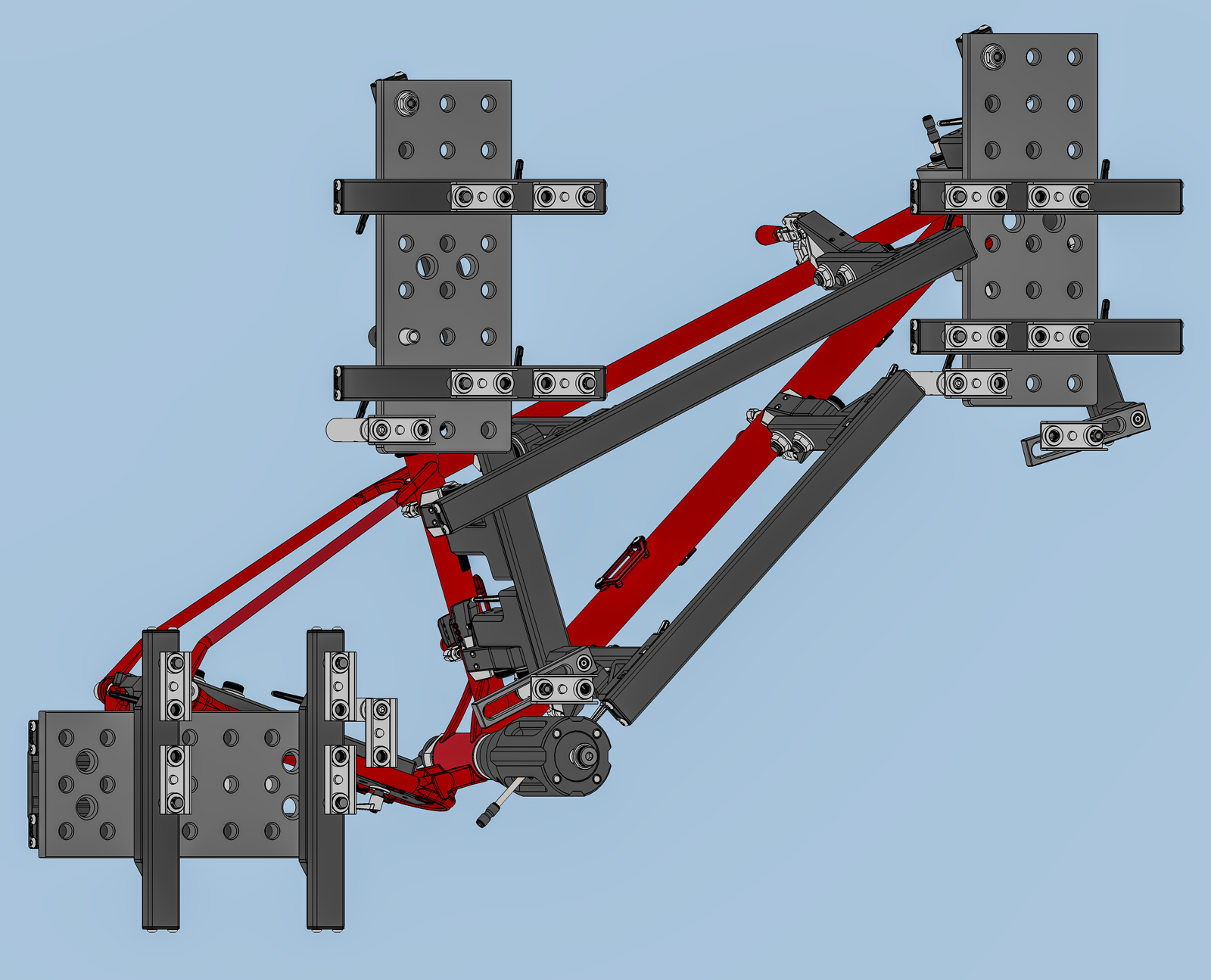
Below is a graphical representation of what has been prescribed.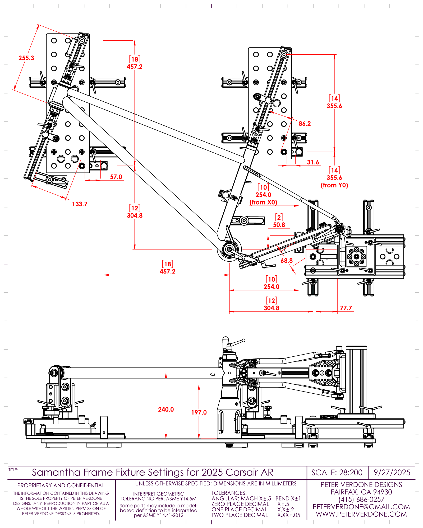
Relatively simple methods that leverage extremely deep understandings are spread throughout the design. The rear center ‘Y’ dimension is set using the length of a hypotenuse to the measurement pin. This is a counterintuitive method that solves a complex problem simply. The ‘X’ dimension is (optionally, like many other settings) set using gauge blocks. Very fancy yet simple and precise.
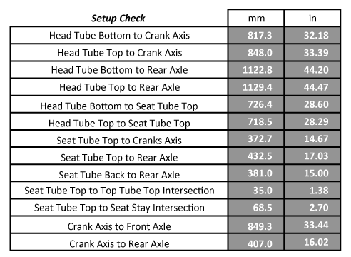
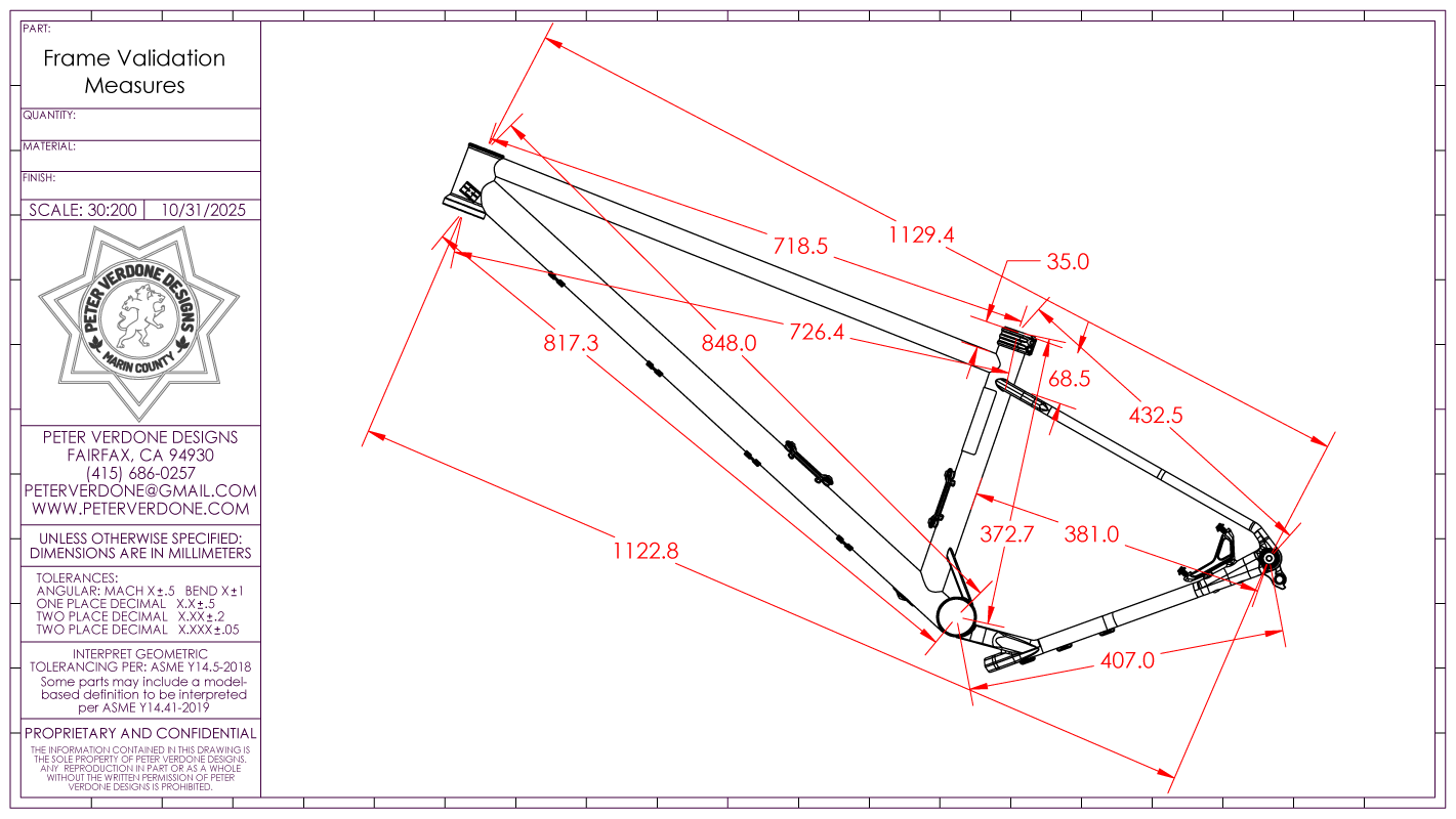
Since the calculations and fixture settings are quite abstract and only make sense within the context of the system, validation dimensions are provided to measure points on what will become the actual frame. This confirmation will help catch any possible mistakes. Others would do well to copy this math.
Notice that the head and seat tube rails build from a pivot that is located far from the crank shell axis. That is by design. Since these raster tables are so precise over large distances it makes most sense to build as close to where the handgrips and saddle will be located. This ensures that those parts end up being placed as accurately as possible since they will be noticed most by the rider. A legitimate argument could be made that the front wheel axis is most crucial to place the head pivot. We have to make a call at some point and I decided on hand grip as the tube in the structure that is being held is most close to the hand grips rather than the front axle. This also contributes to a much cleaner fixture design. Seven of one, half a dozen of the other. I doubt a choice one way or the other will have more than a couple thousandths of an inch difference.
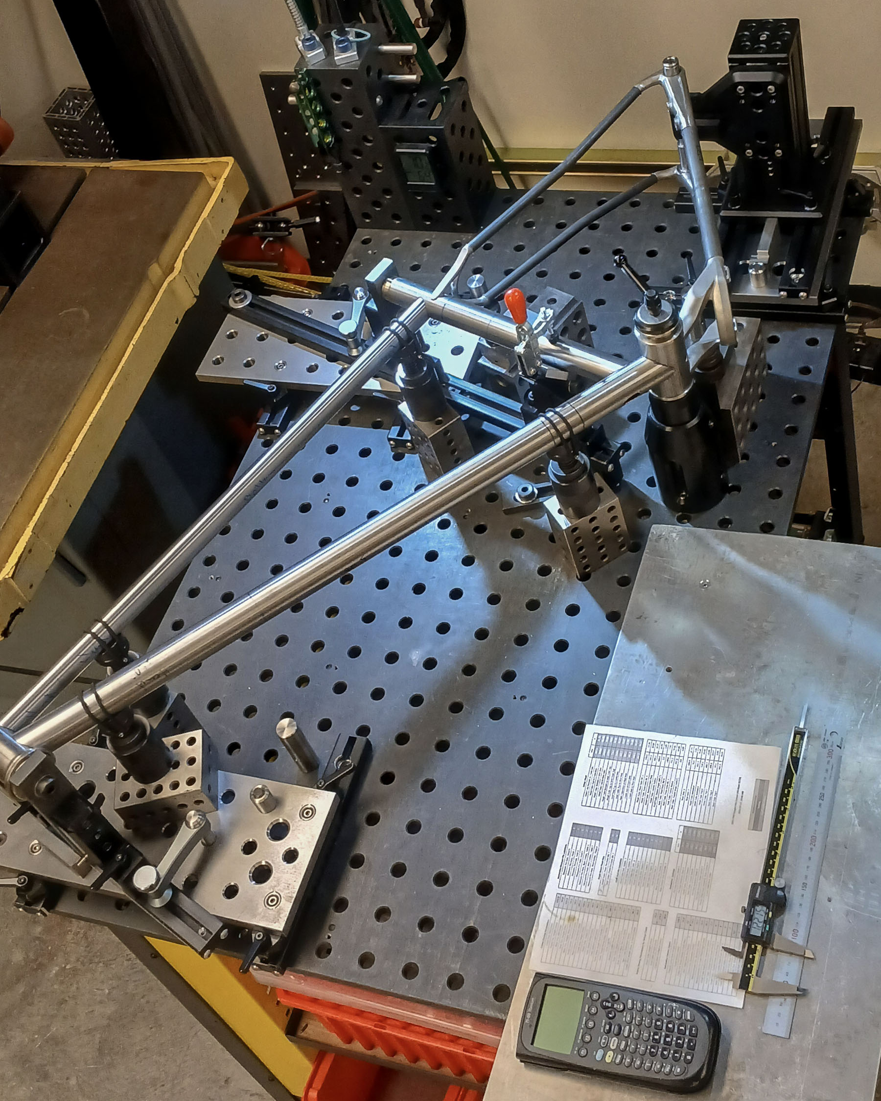
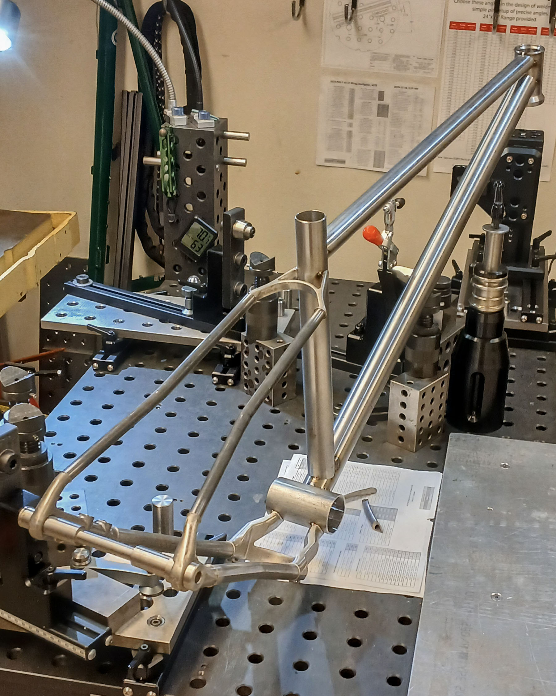
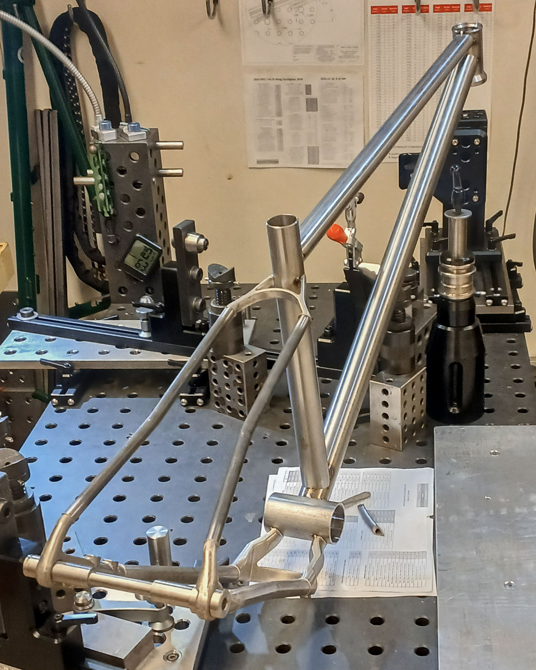
Once the frame has been fully tacked and will be removed, the head tube and seat tube cones slide clear, the rear axle tower slides back, and the frame can slide straight up from the crank axis tower. It’s an effortless process unlike many other systems. That is by design.
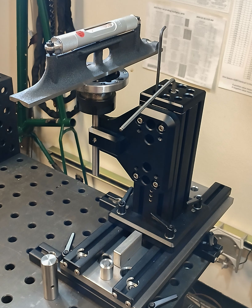
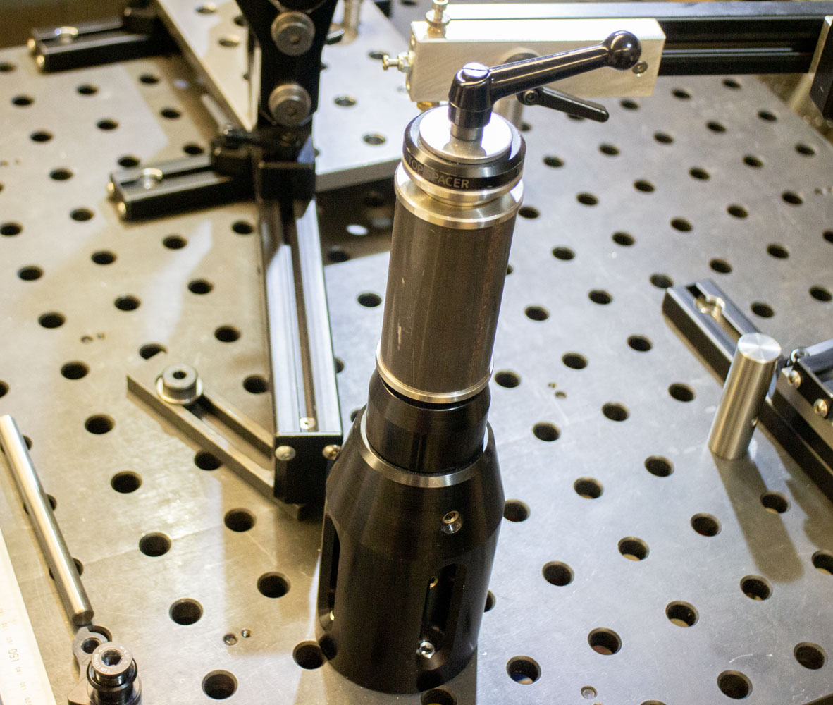
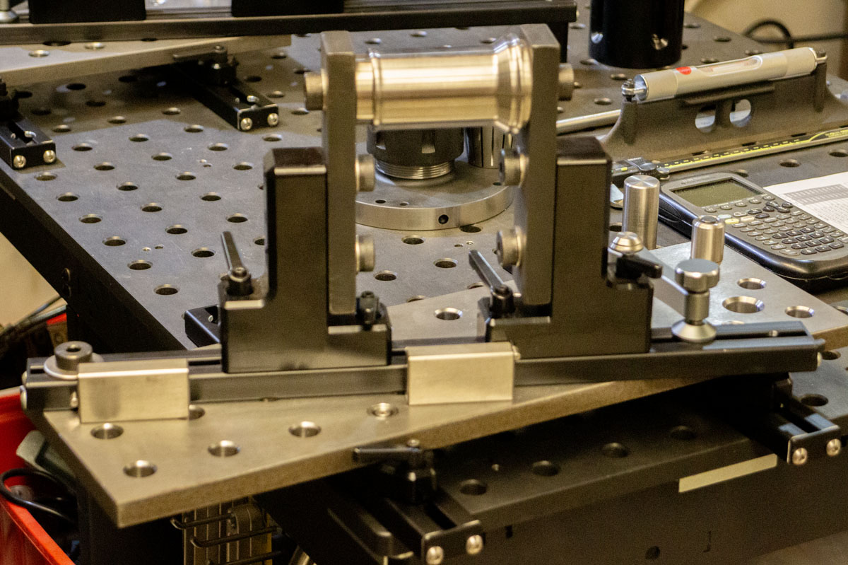
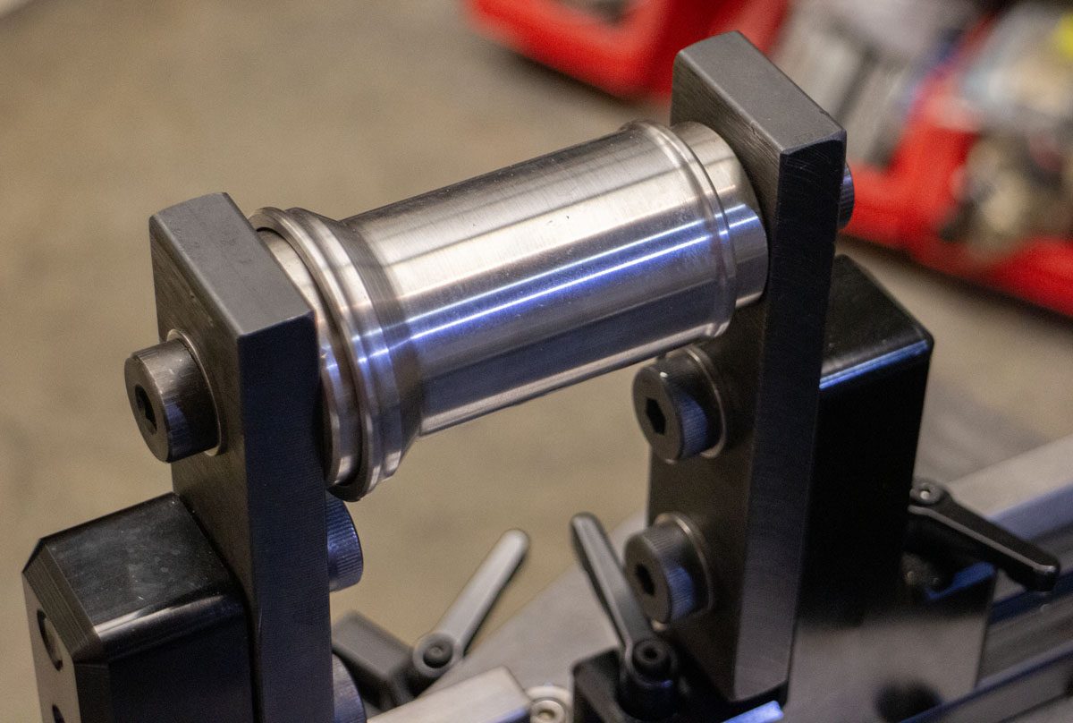
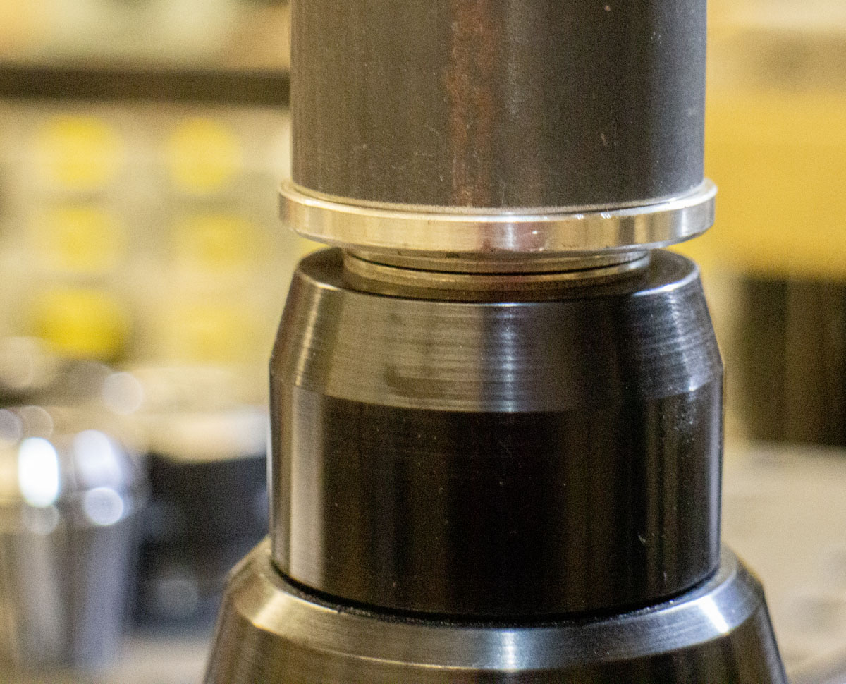
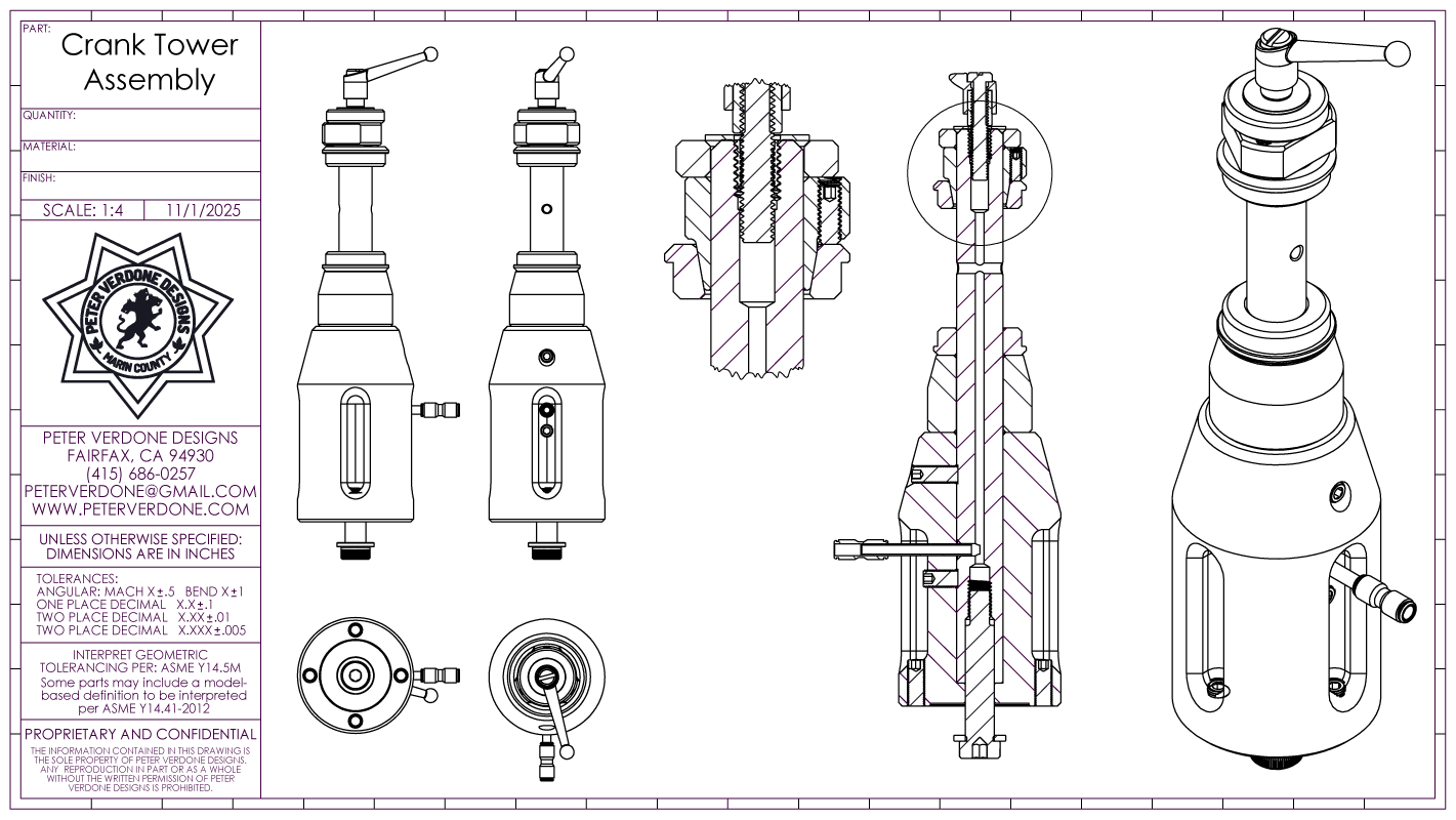
The crank tower is engineered to be rigid, precise, calibratable, and fully constrained. It supports both sides of the shell, allows purge gas flow, and resists weld distortion—all while remaining user-friendly. Wow, that’s a lot. Even more that it was made in a basic manual machine shop.
Unlike almost every frame fixture in the market, the crank shell is held rigidly concentric on both sides. Ensuring that the crank axis ends up being perpendicular to the center plane of the frame is a crucial detail that seems readily obvious. Significant welding distortion takes place in this area. I make sure that both sided are supported well.
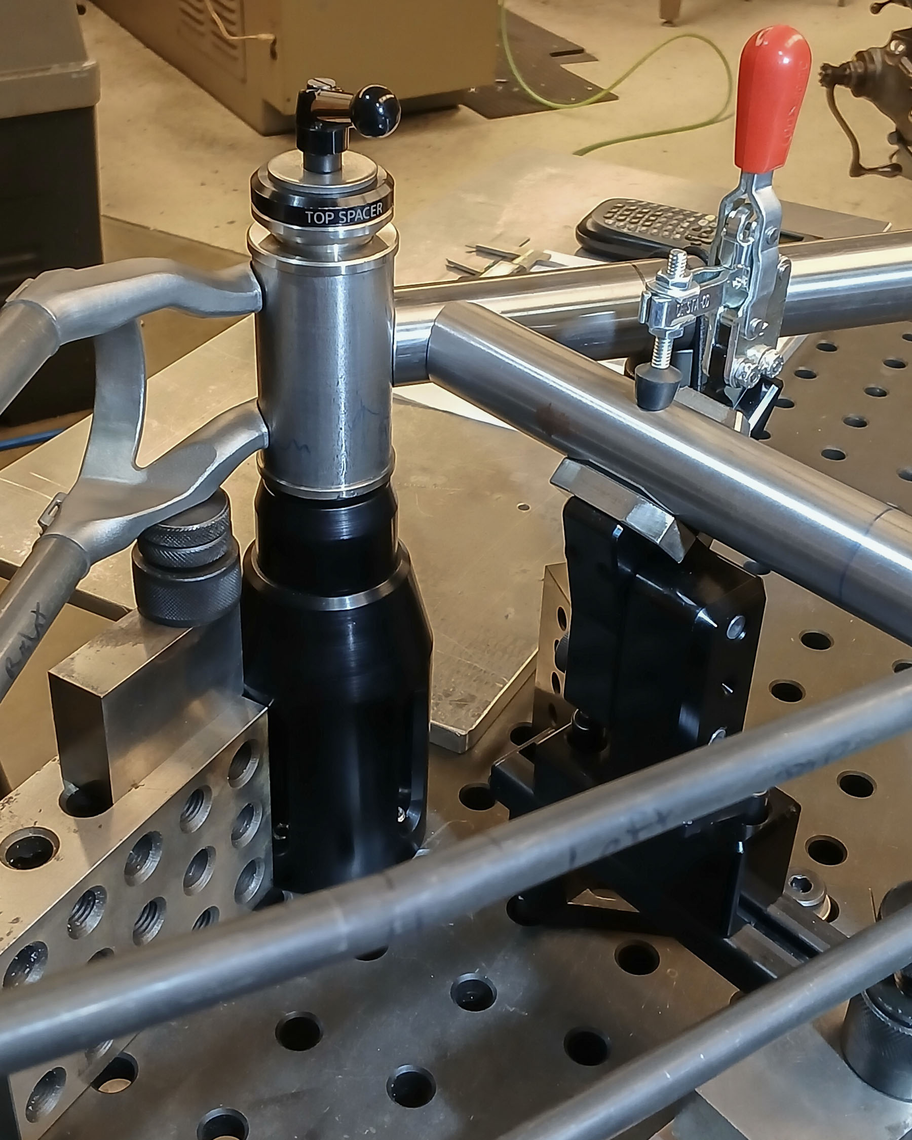
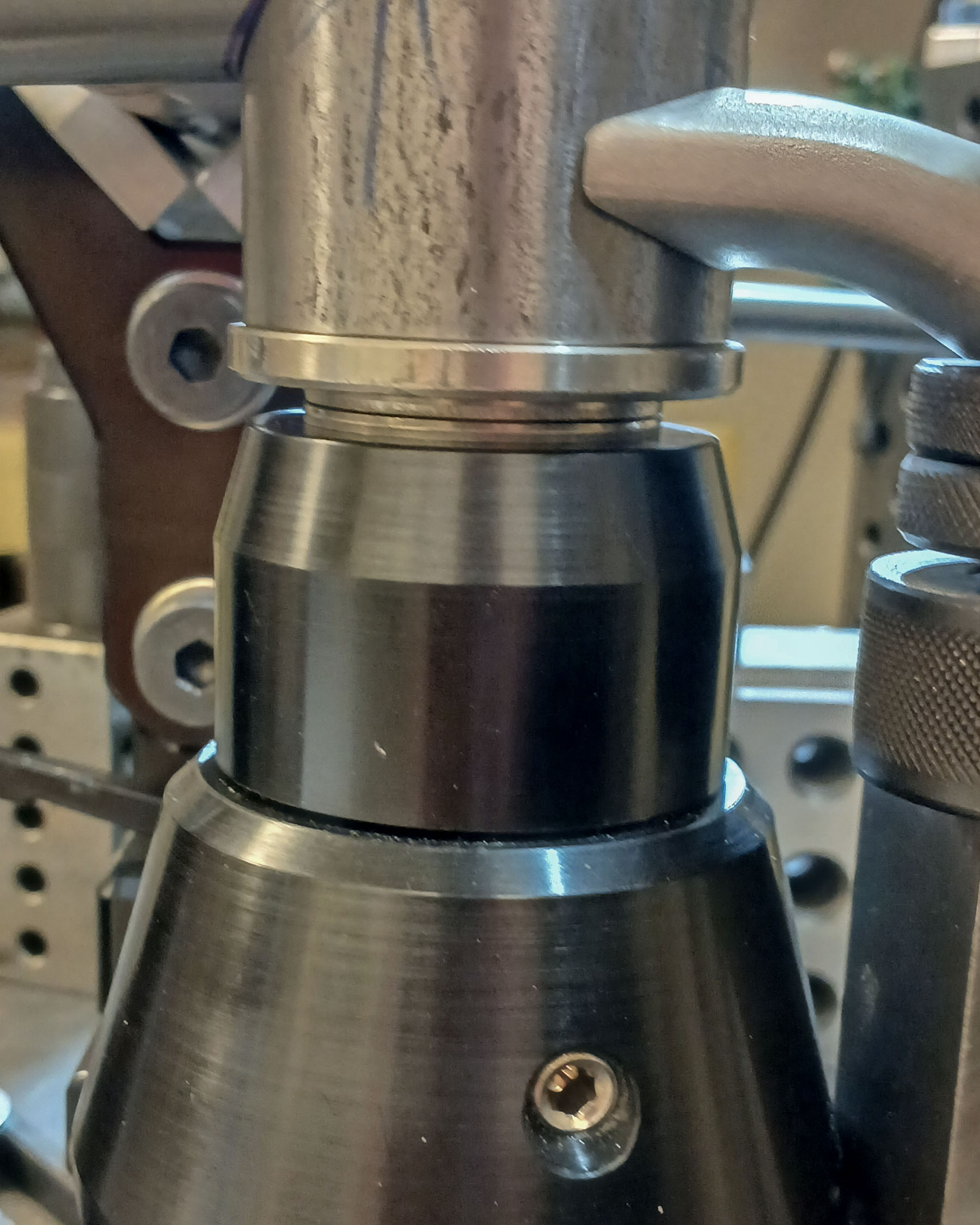
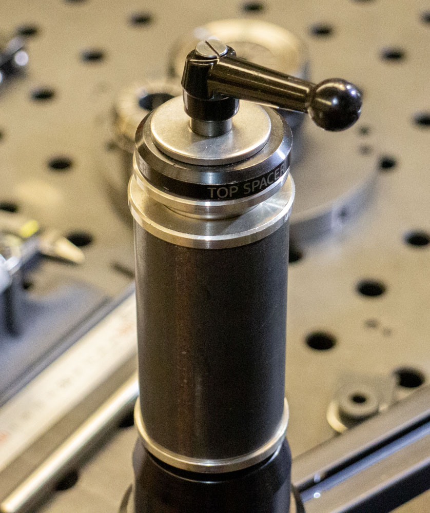
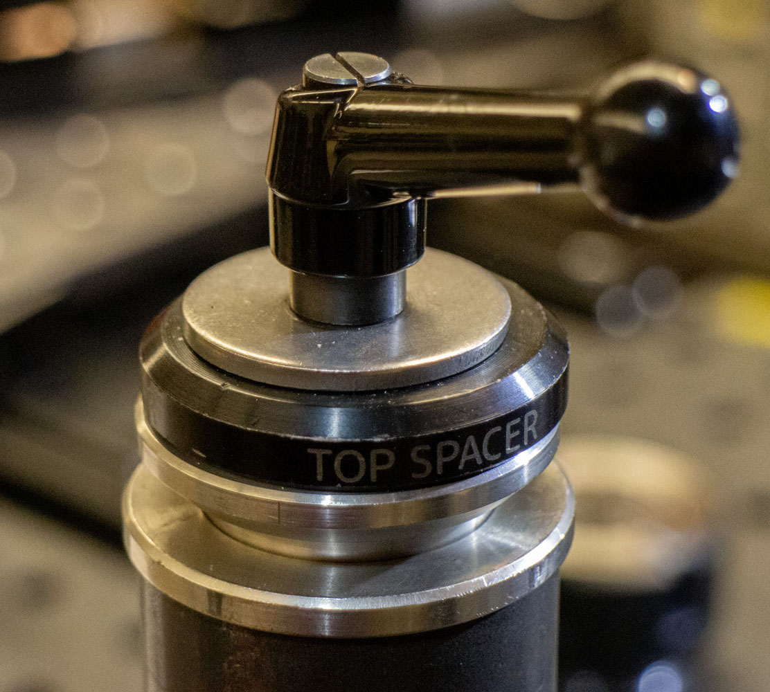
A taper split of the top cup ensures that even if weld distortion causes huge binding forces on the shaft, the frame will be released easily. Notice the future version of the taper puck. It has a gear puller mechanism built into it. This is a design improvement that has been waiting 5 years to become real. Soon.
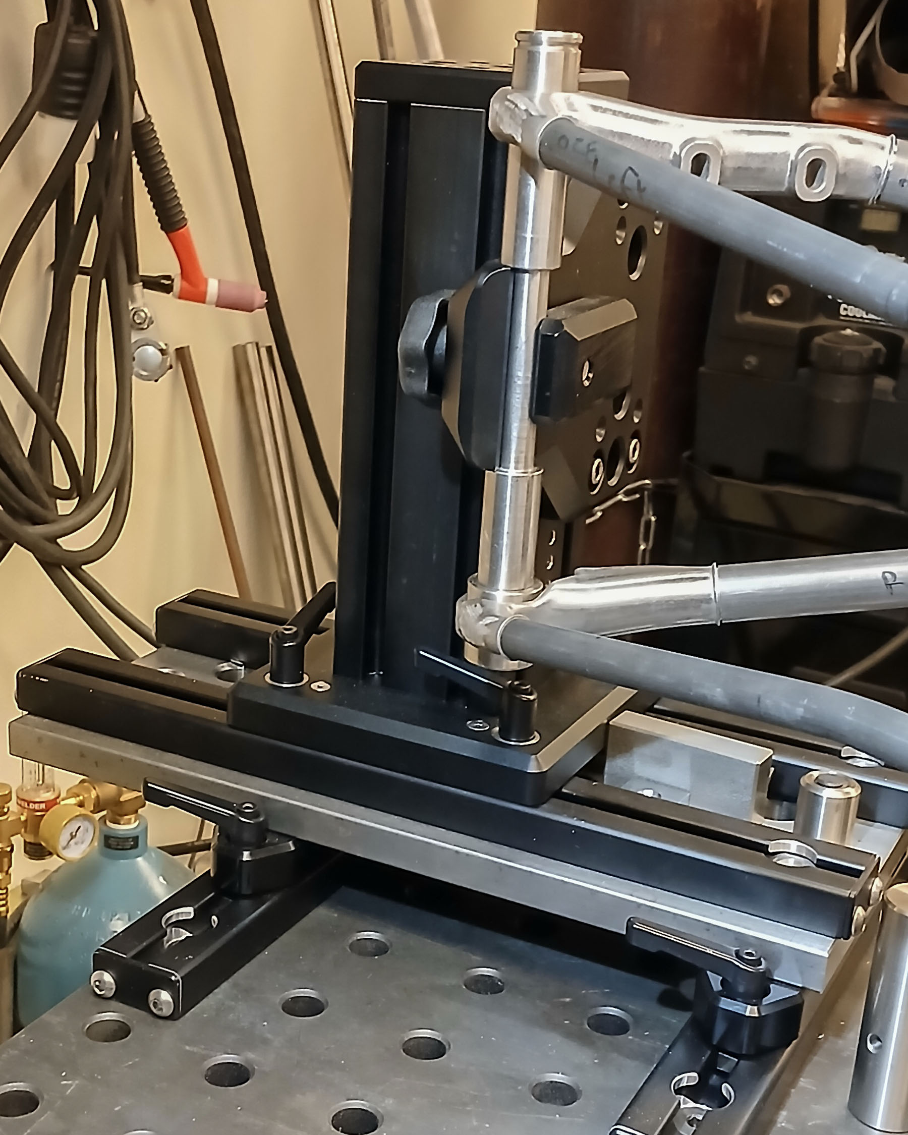
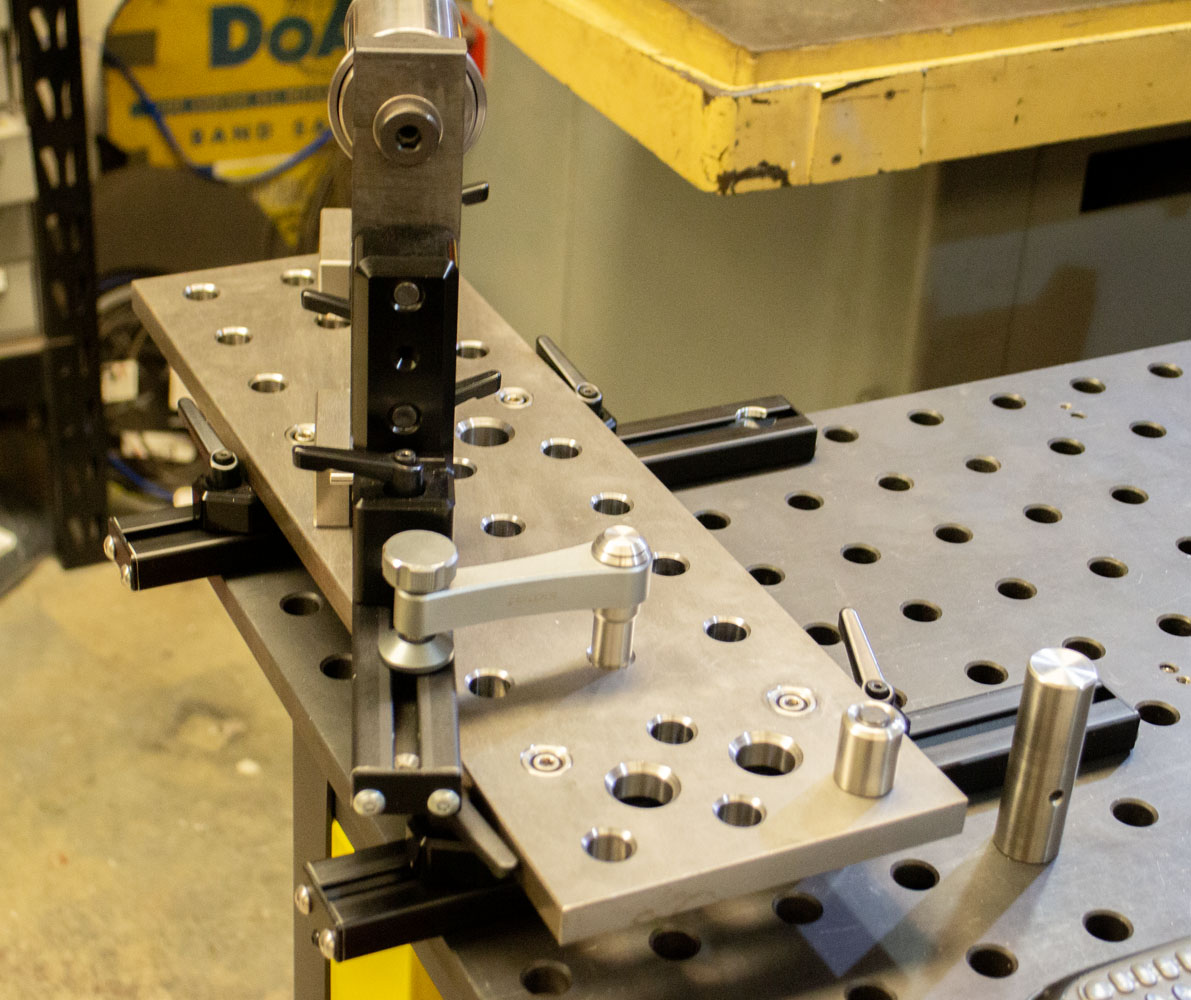
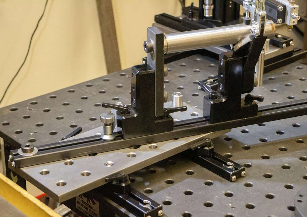
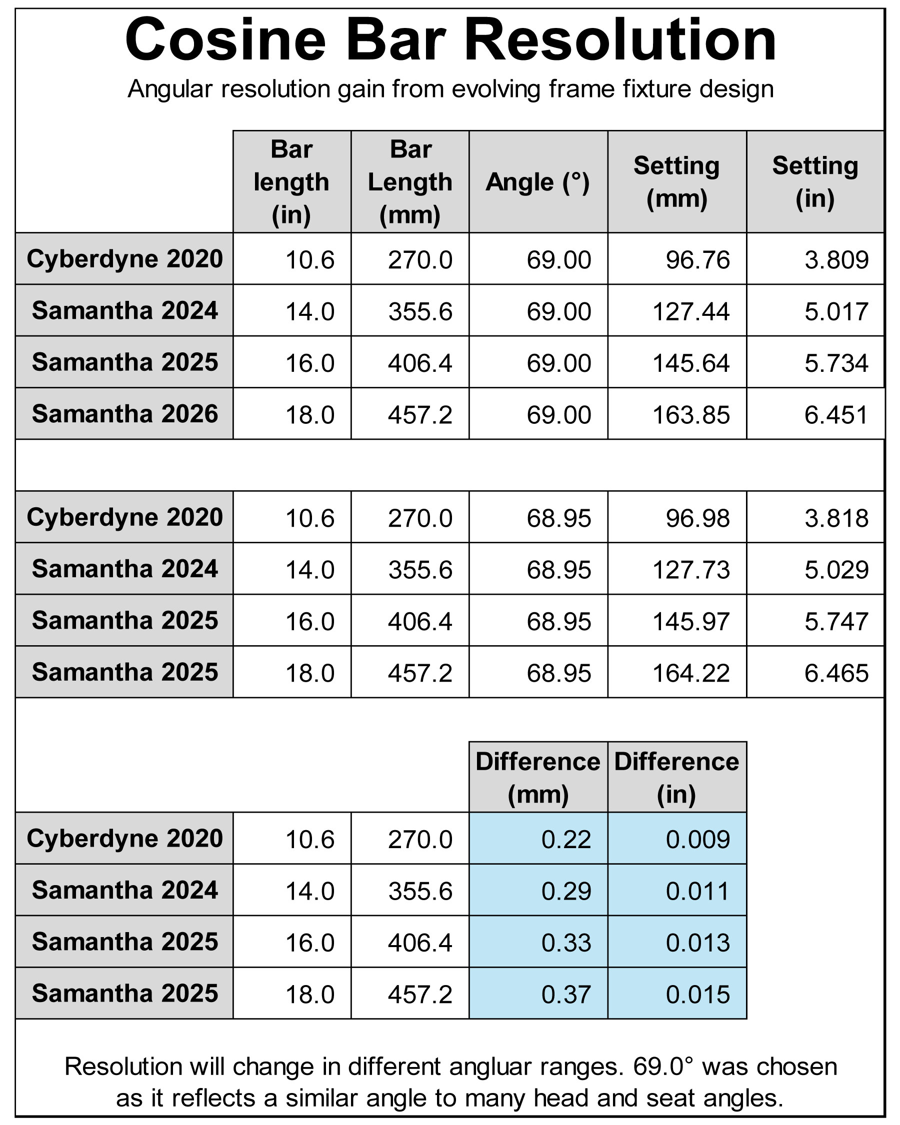
The head tube beam plate was extended 4.0″ from the original iteration. The added space to work on the plate is wonderful but the improved resolution of the head tube angle placement is even better. This allows the cosine bar to grow from 14.0″ to 18.0″. Pretty amazing. Because of this, the linear measure difference when setting from 69.00° and 68.95° is 0.015″. Show me another fixture working at this degree of precision!
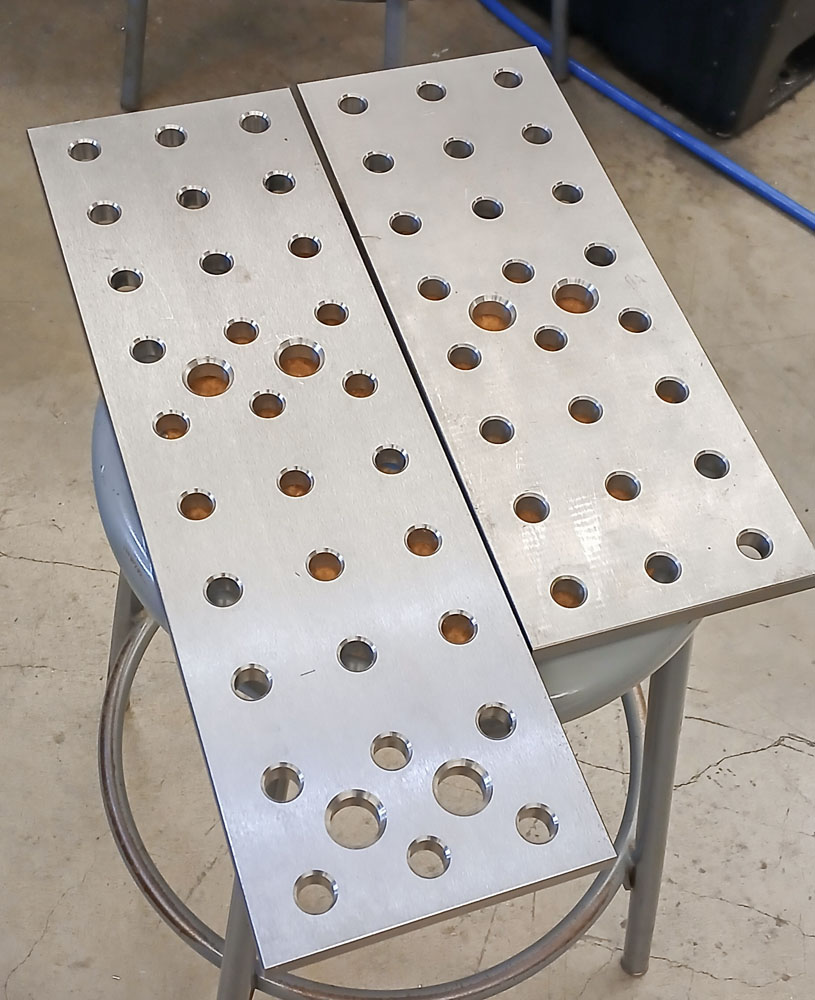
These plates are cut from BuildPro TM57846SV-01, Reversible Table Plates, For MAX (Slotted) Tables. Another big investment that can be multiplied across hundreds of different projects.
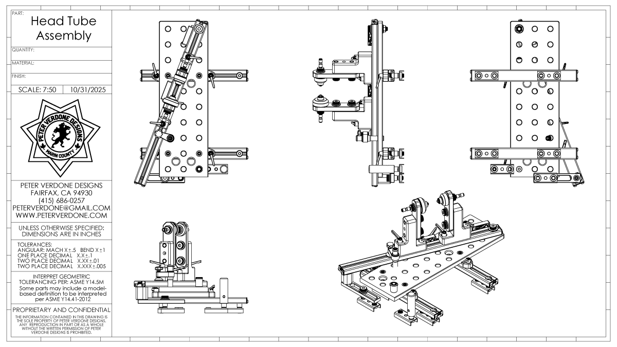
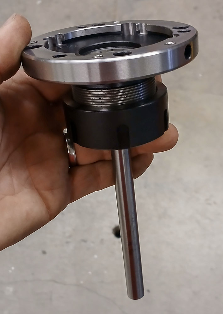
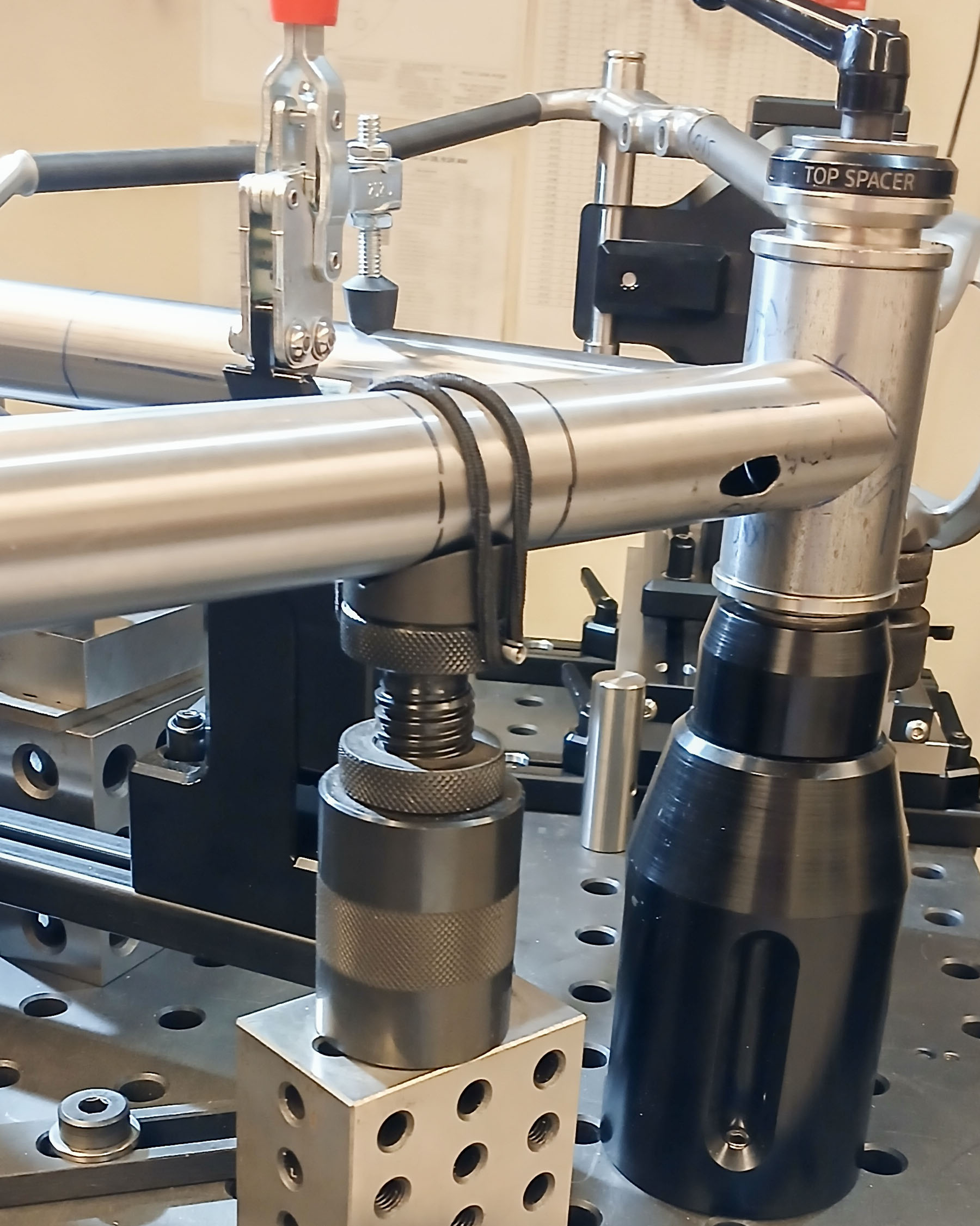
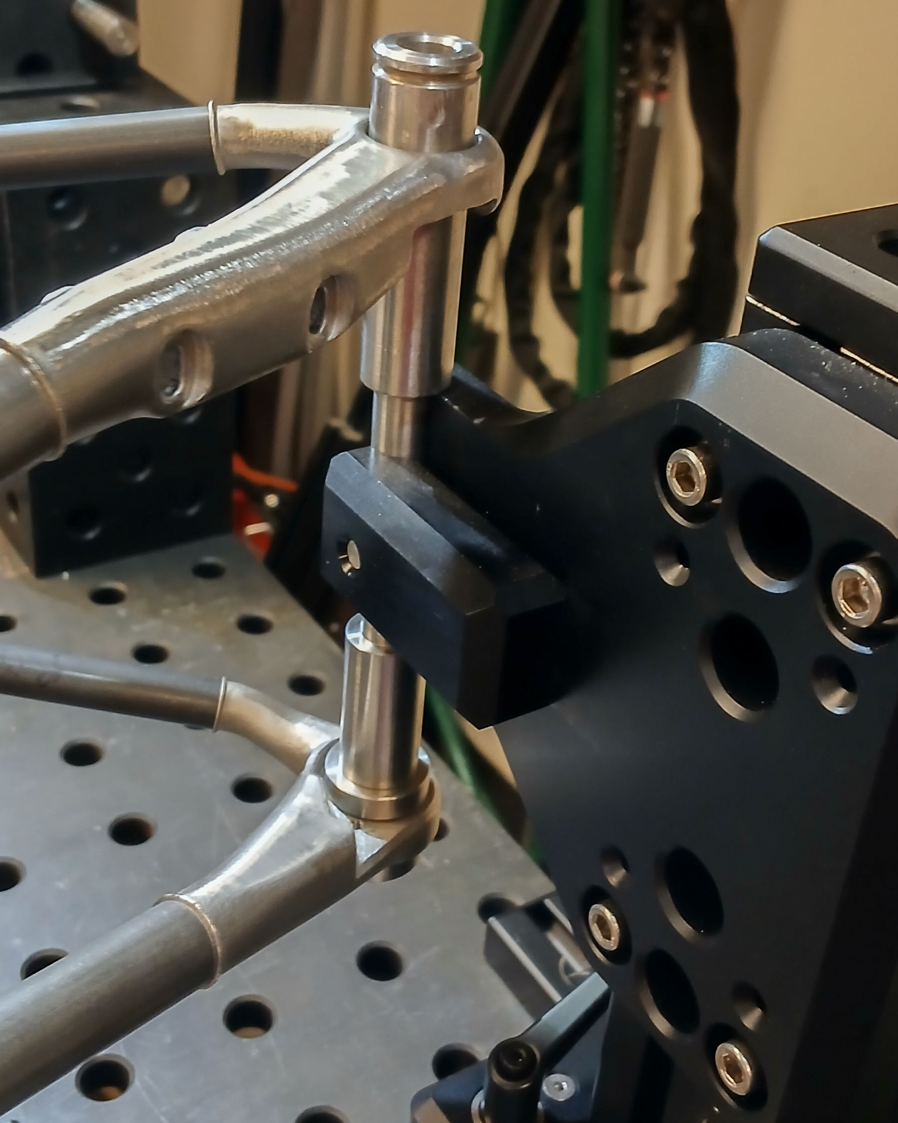
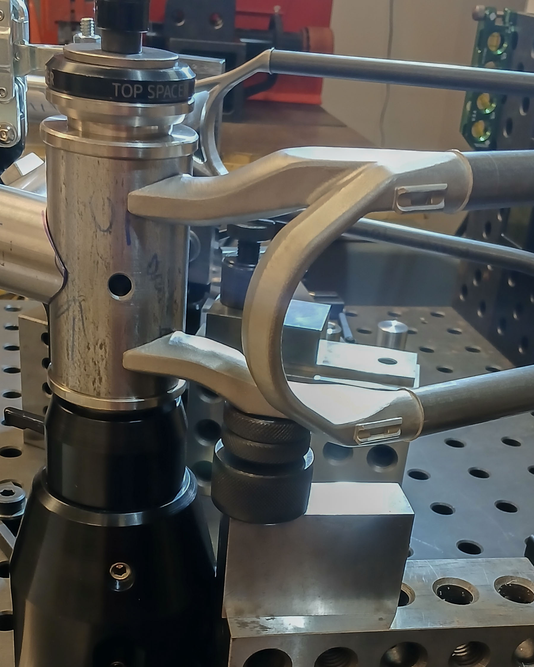
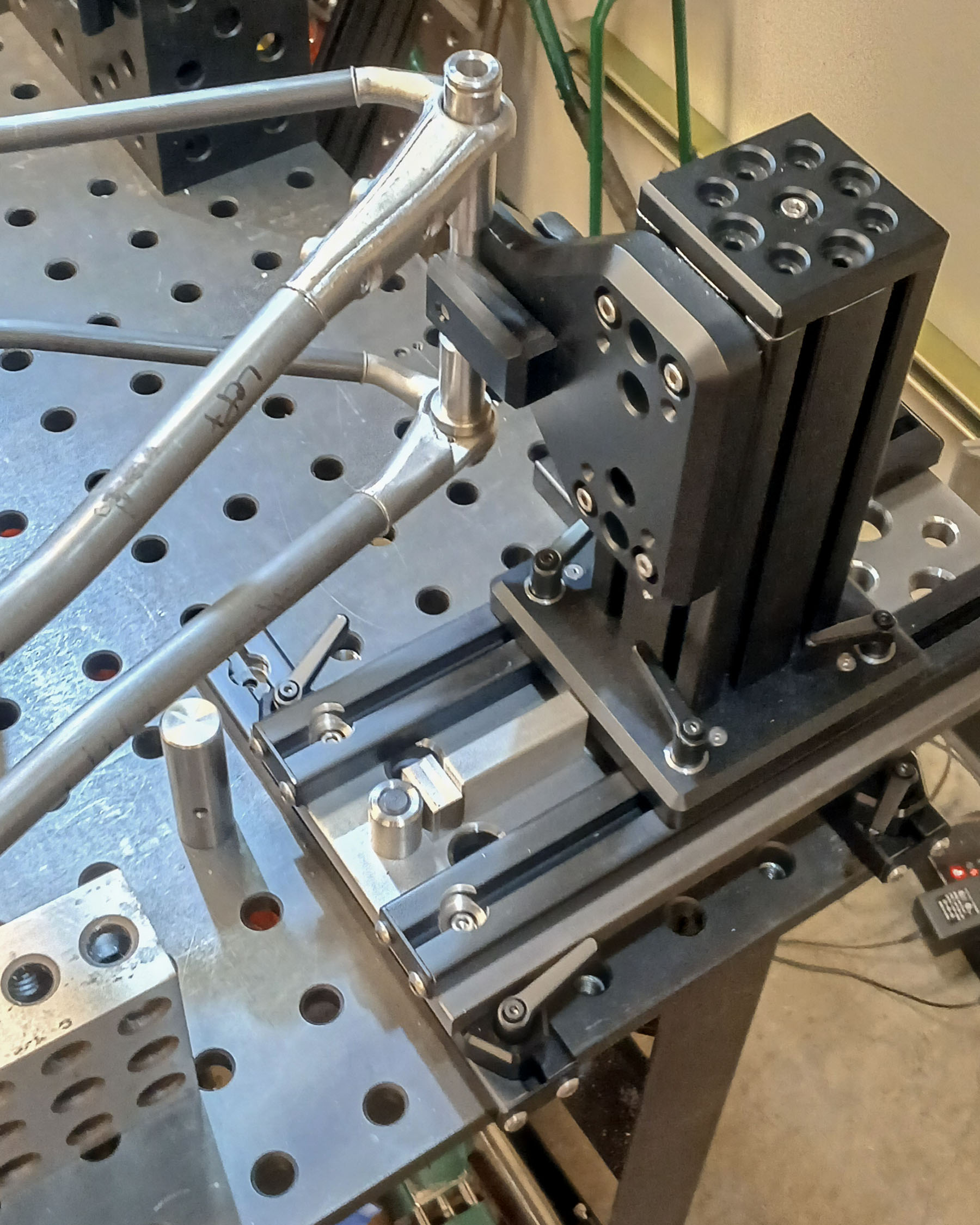
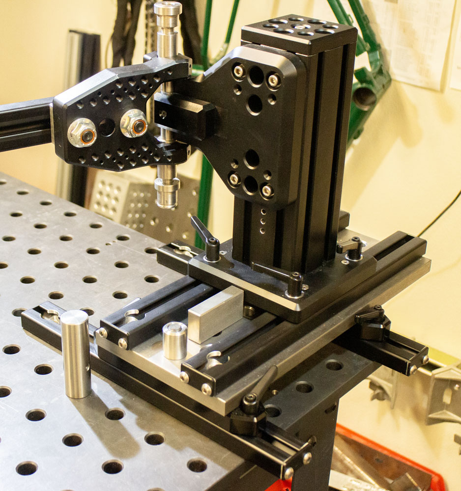
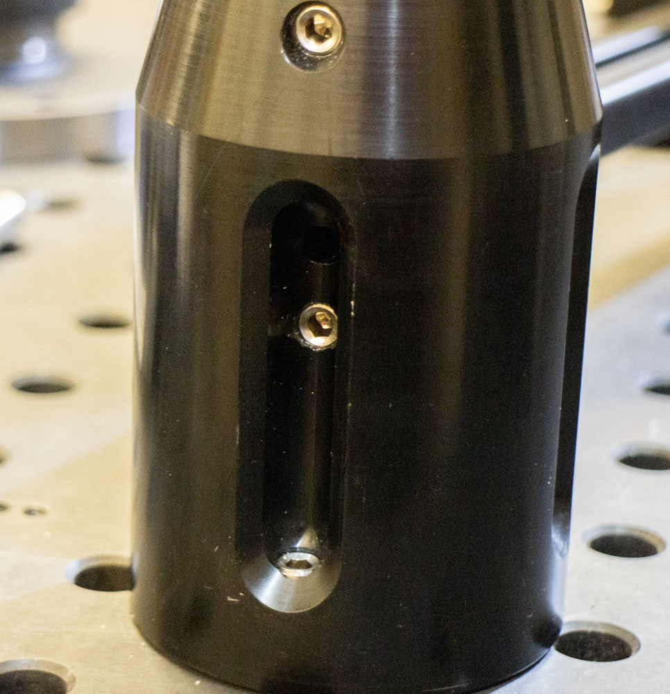
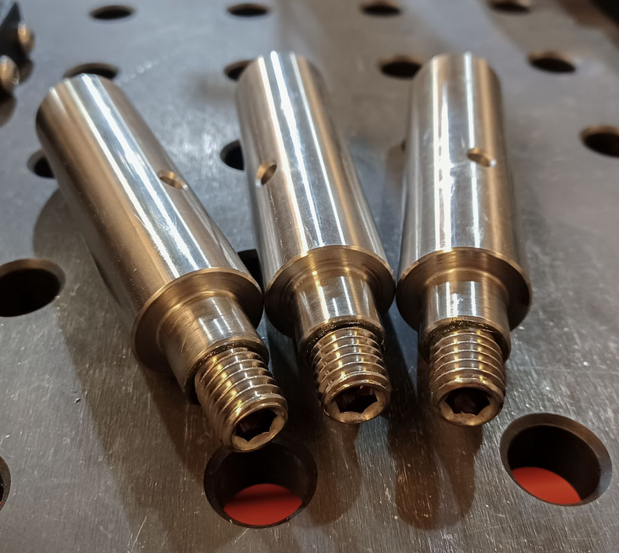
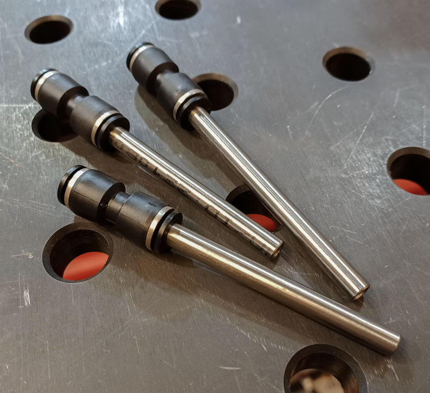
The locating cones that hold the top and bottom of the head tube and the top of the seat tube are mounted as to maximize rigidity, precision, and low cost while also providing purge plumbing. The simplicity of this cannot be overstated. They are also extendable as they can be used in any location within the system that has a raster hole.
Shown below is an IS52, head tube top, and seat tube cone setup for mounting to various sections. In the case of the head tube bottom, the critical datum where the lower head bearing mates to the head tube is used rather than the base of the head tube skirt. That should make sense to everyone. First principles.
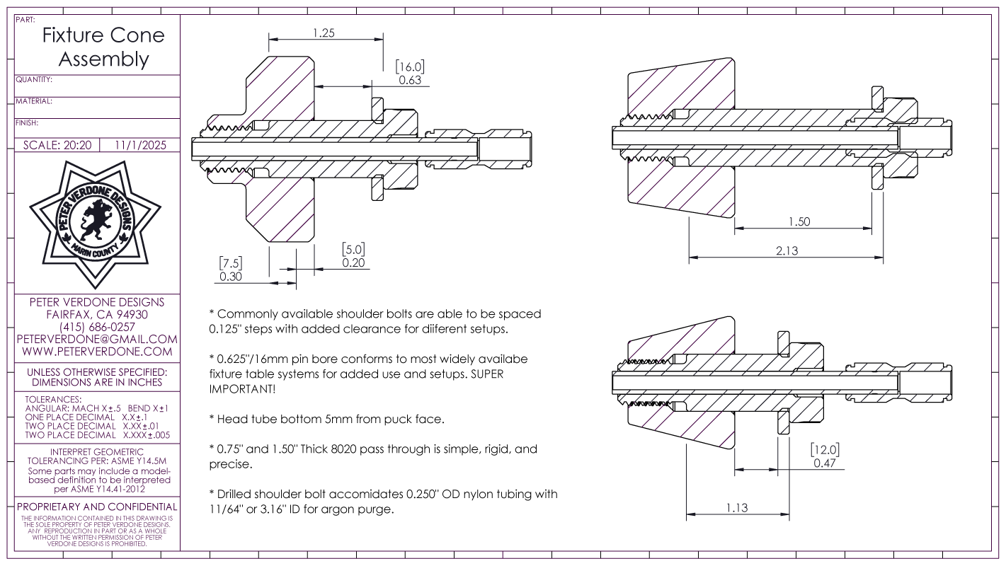
While I don’t work with titanium (currently), I’ve left that option open. Purge fittings are placed throughout the front triangle of the fixture. At the top and bottom of the head tube, the top of the seat tube, and in the crank shell. The purge plumbing for the fixture is stainless steel tube where it may encounter heat during welding. Those tubes then have a push-to-connect couple to common 1/4″ nylon tubing to tank. There is a fancy trick to making this work properly. These are really cool.
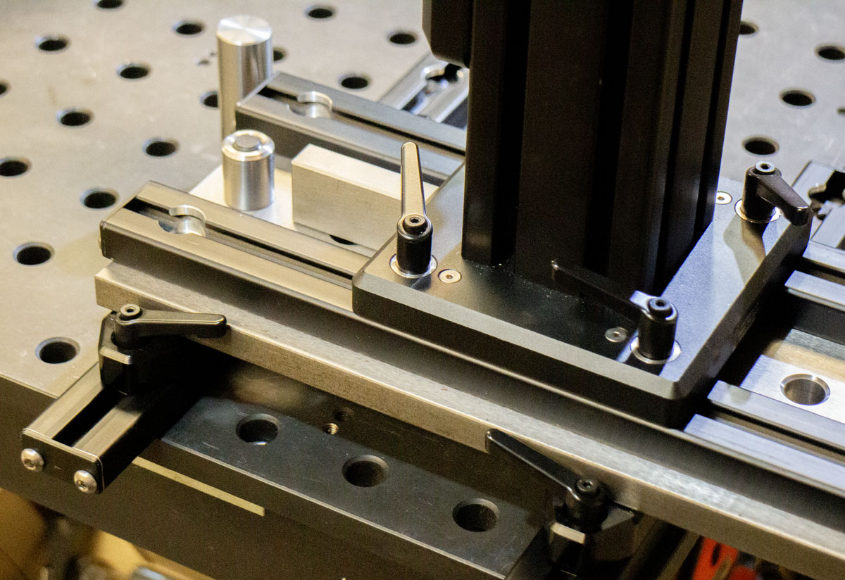
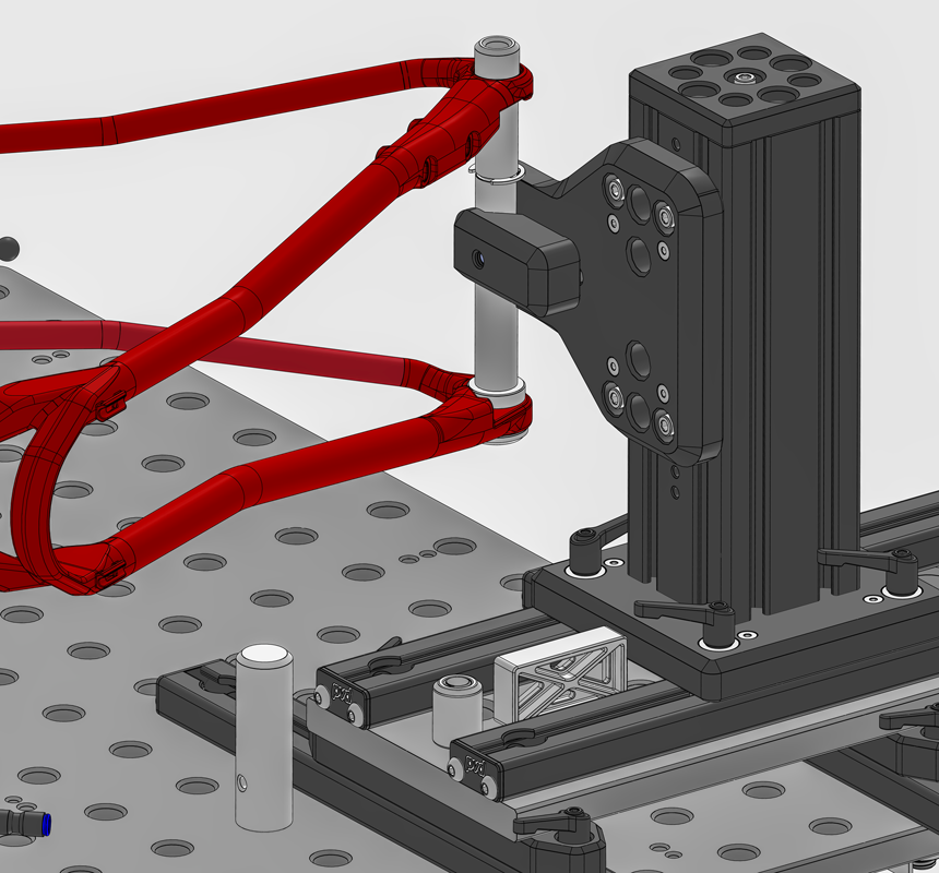
I recently produced a (another) new set of slide rails for the fixture that have a 10.00″ hole spacing. This allows the fixture sub-assemblies to be placed on the table without any disassembly. There are situations when working with large frames and the small RhinoCart where some extension past the surface limits is needed. An additional 8.00″ hole spacing is provided along with the 4.50″ extension to go over the edge. Slight disassembly would be required to do this, but the option is available. In time when I’m using a larger table, this won’t be necessary. Since the seat tube rails don’t have this issue (they have ample table space), they are 10.00″ hole spacing with just 7/8″ on either side.
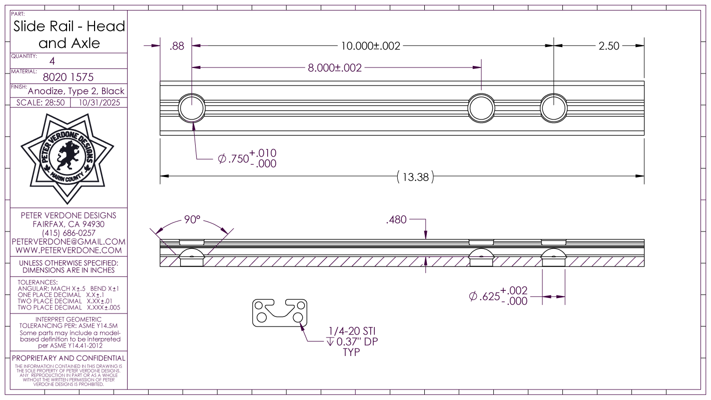
I investigated dynamic rail options for use in this system, but they fell short. To maximize both rigidity and precision along with cost as a factor, 8020 1575 rail continues to shine. It may seem low tech for such use but it turns out to be the most advantageous method. Custom t-slot rails could be produced to get even more rigidity and precision but I believe that getting that tiny bit more comes at too great a price.
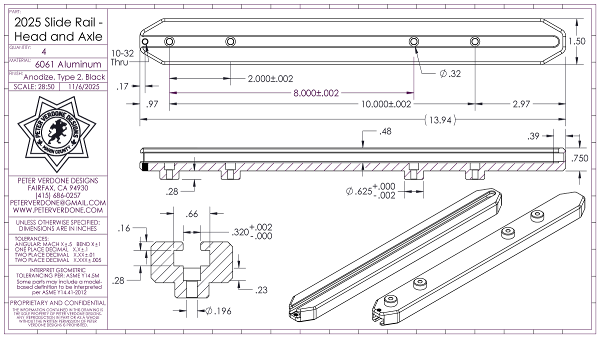
A future version of this rail has already been designed. This would require CNC machining but has some real advantages. Like the slide plate, unitizing the pins with the slot adds several layers of precision. The rail will also be more robust and elegant than the 8020 type. I’ll also be able to have a closed slot end, preventing snags. The rather short 0.280 pin extension in this design is to accommodate 12mm thick table tops similar to Siegmund.
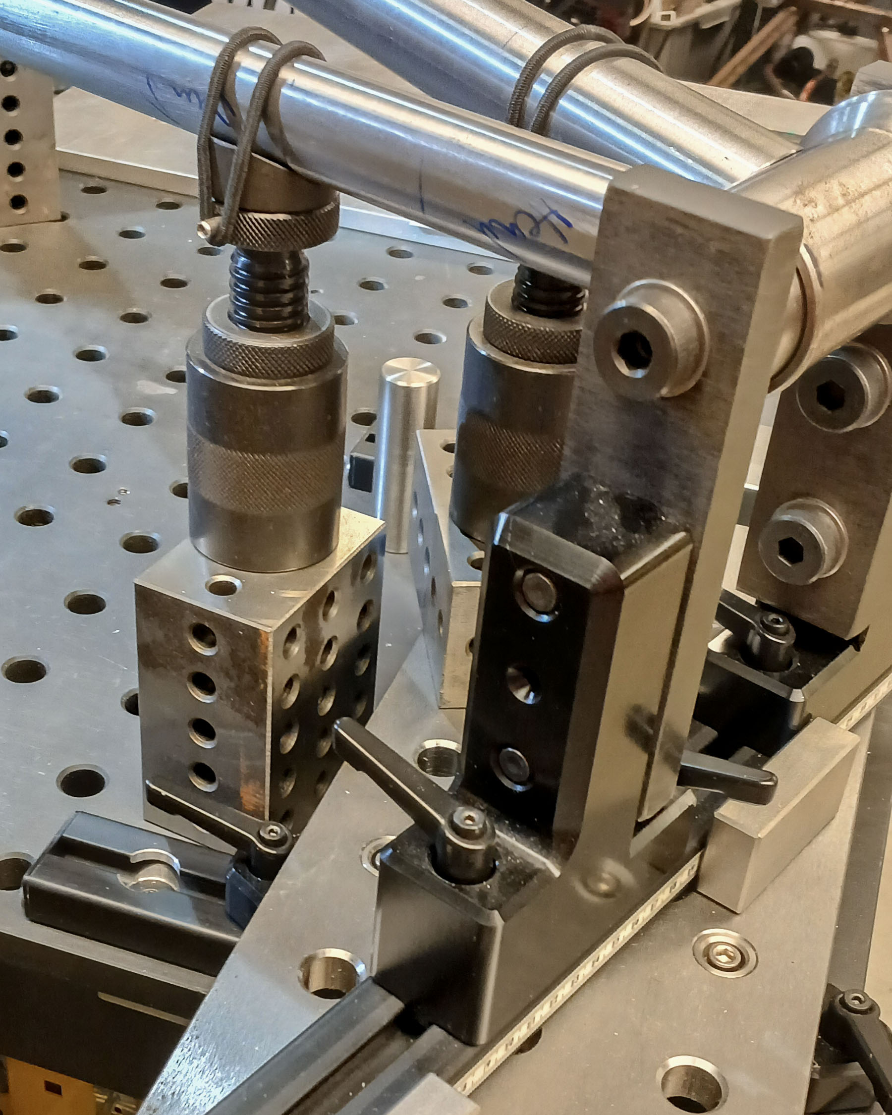
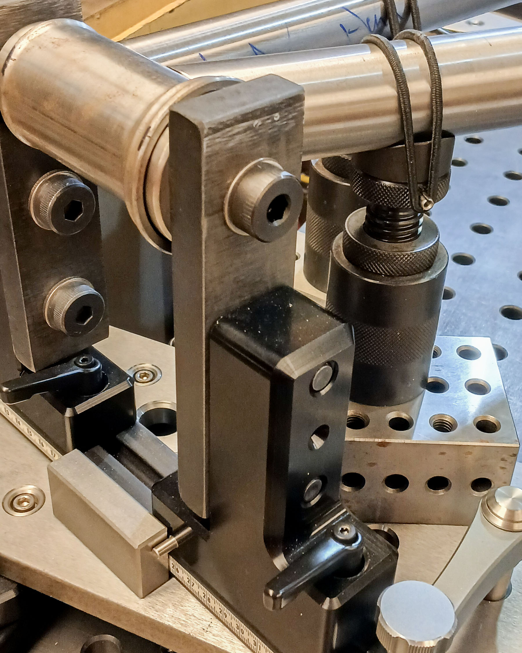
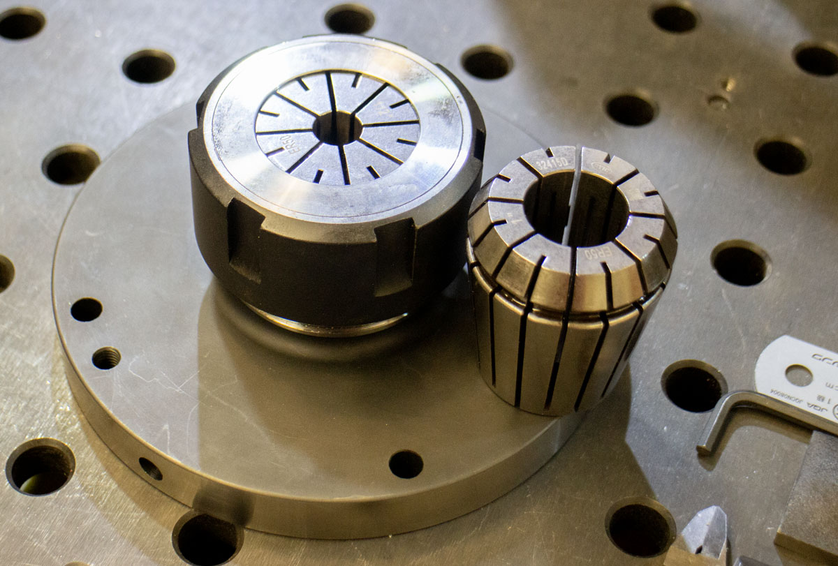
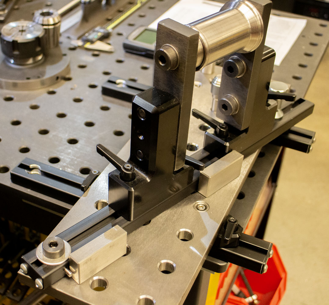
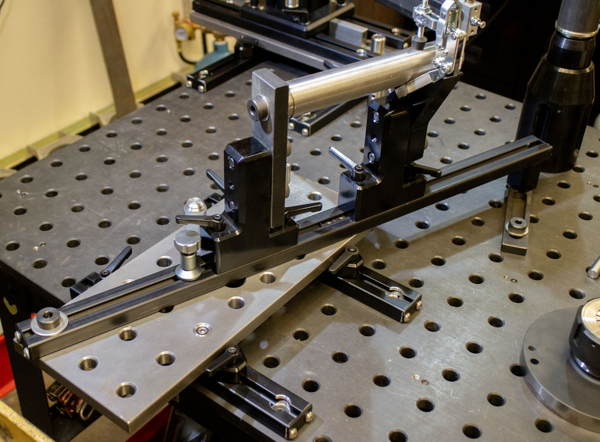
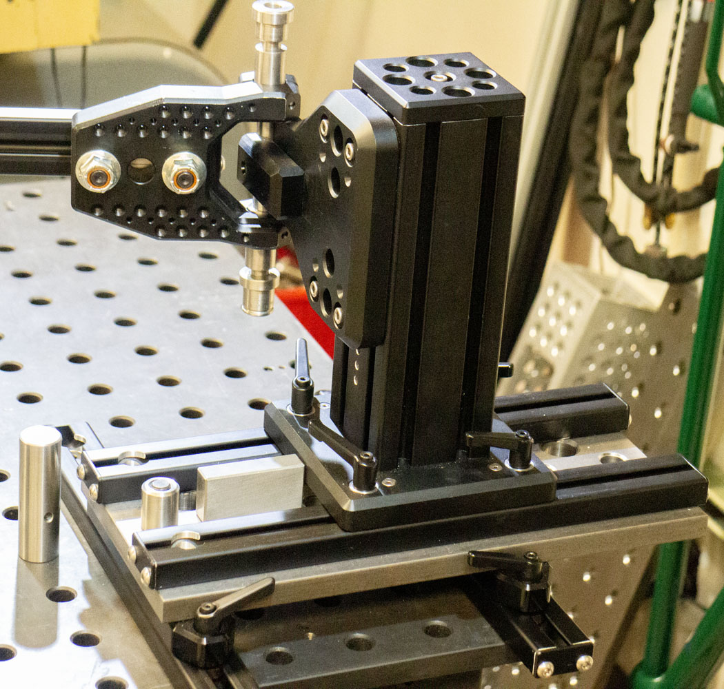
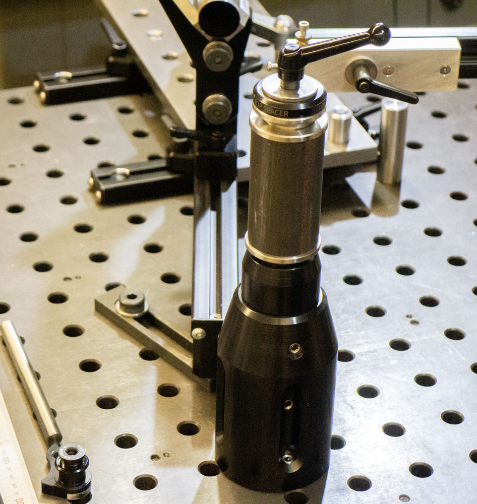
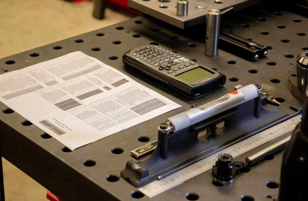
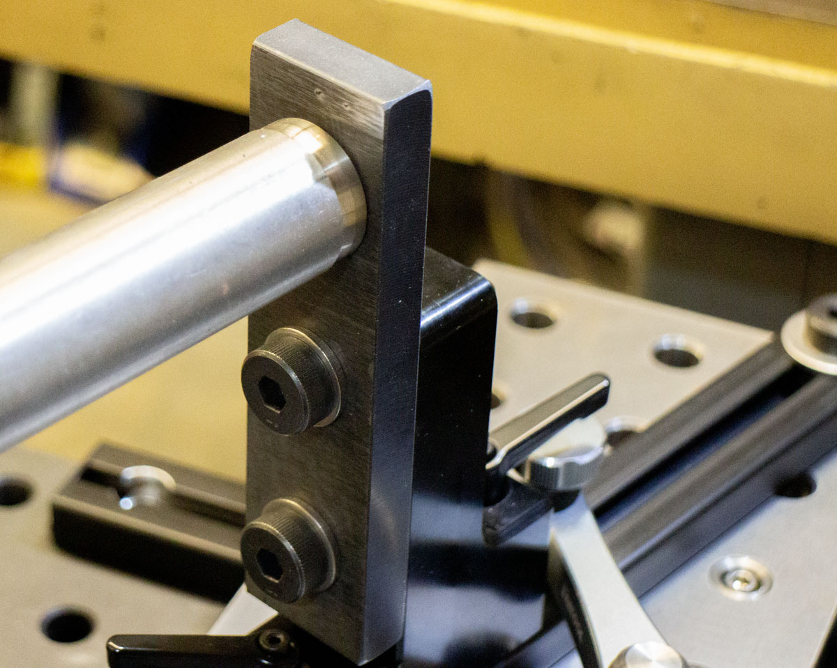
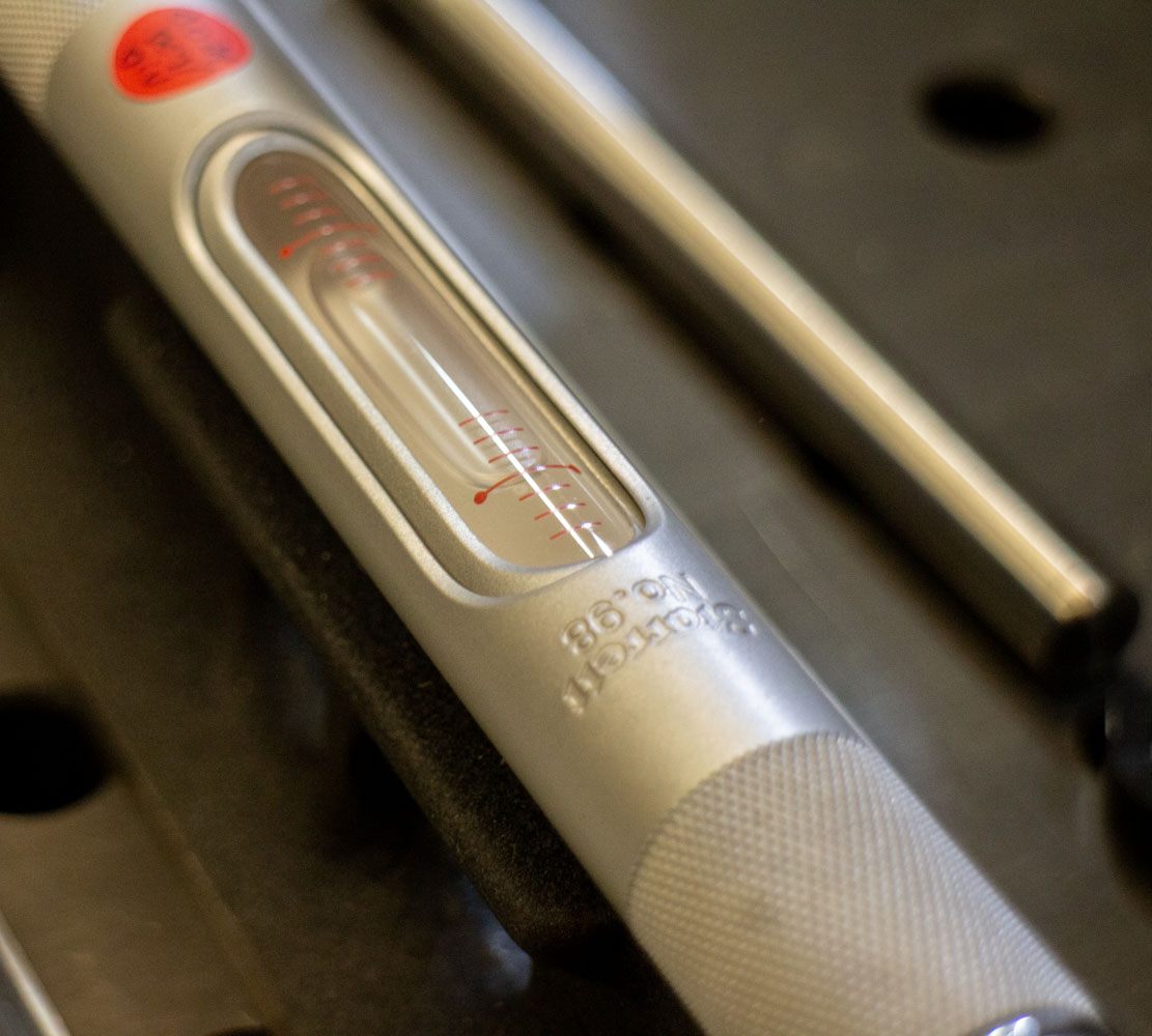
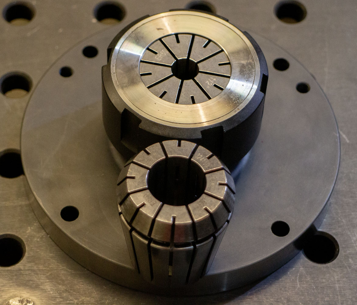
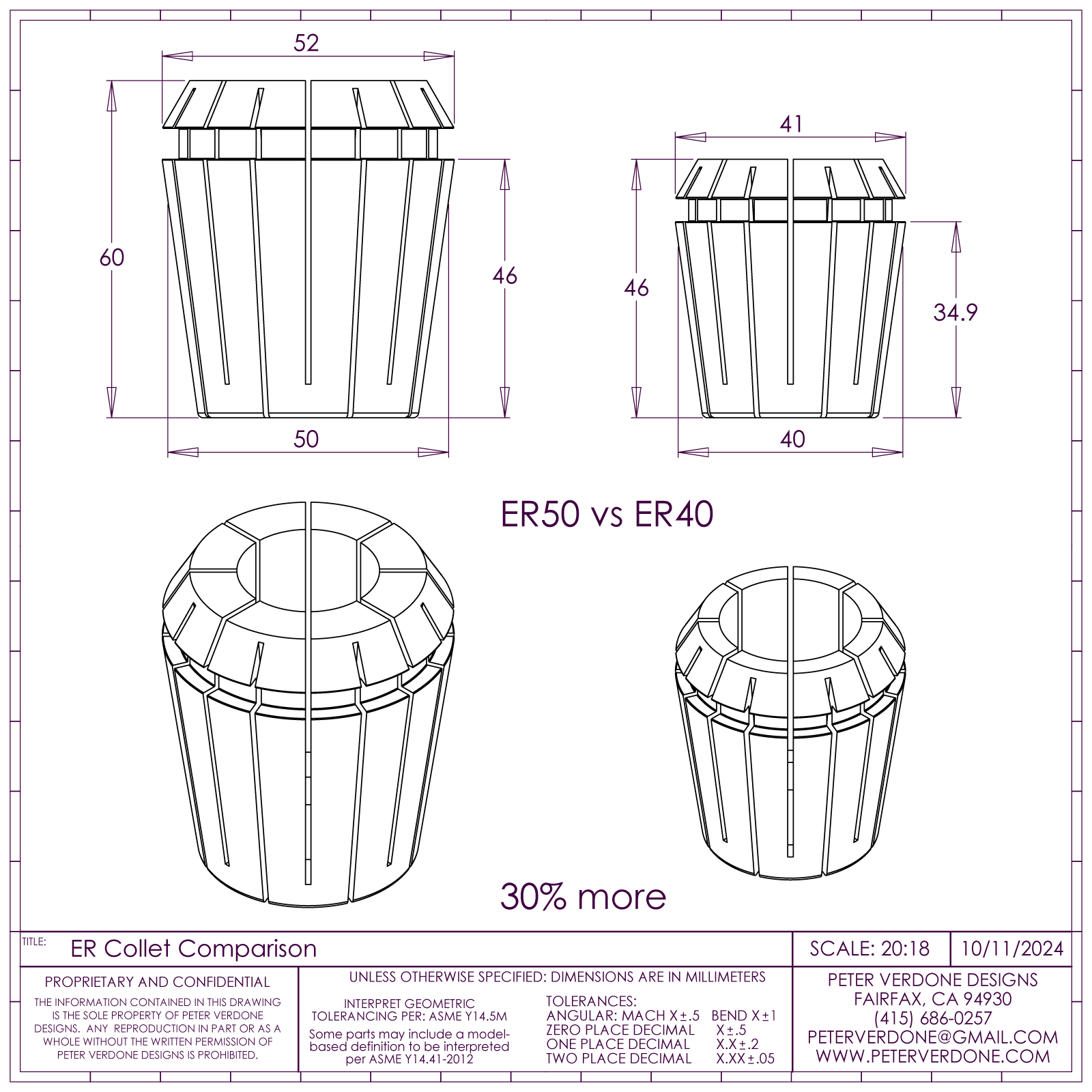
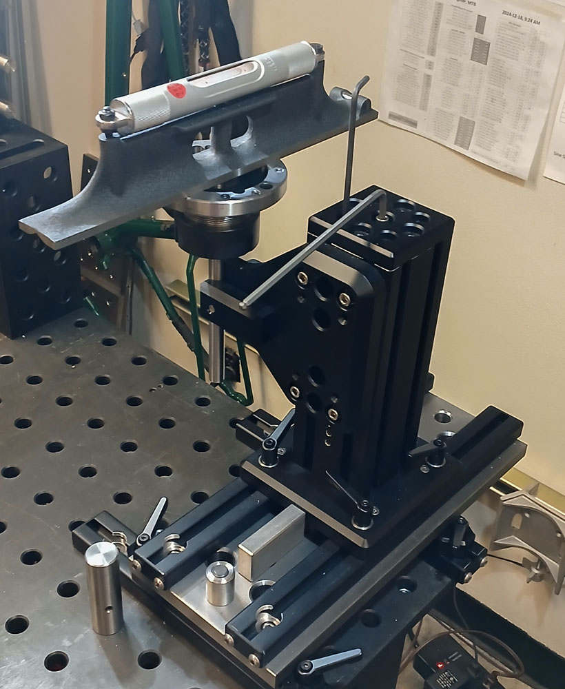
Both the crank shell pillar and rear axle pillar have calibration screws integrated with the design to calibrate the perpendicularity of the crank shell and rear axle axis. Huge 0.0002″ T.I.R. ER50 collets combined with a large diameter (160mm) ER50 collet chuck and a roller bearing collet nut make for a precise, rigid, and repeatable reference. With the chuck fastened tightly to either the 0.50″ or 1.00″ shafts, a nice 0.005″/foot /div machinist level is used to plane adjustment.
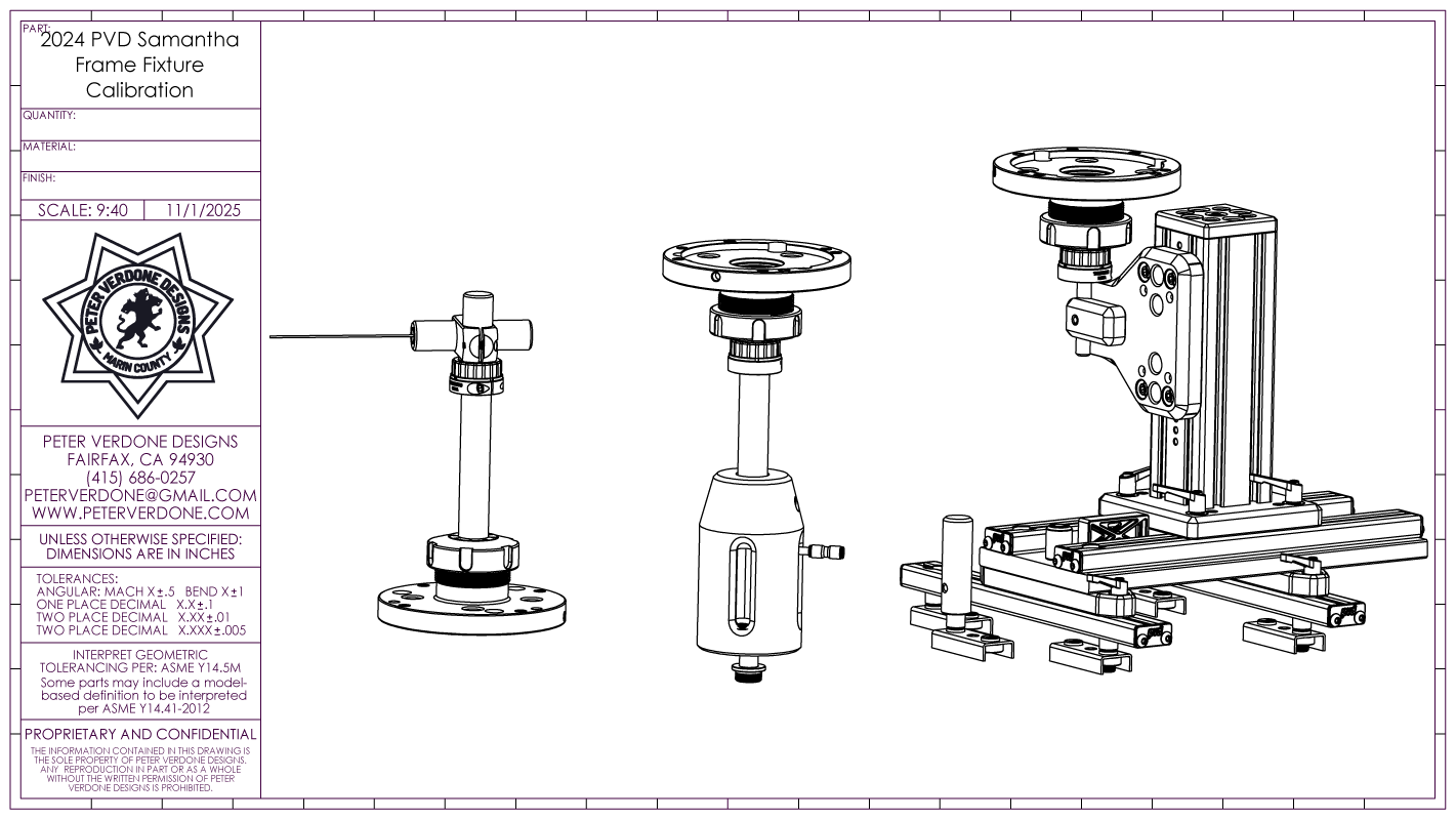
Calibration of the rear axle axis is a fussy little affair. With the collet chuck and level in place, the tension bolt holding the pillar together is loosened slightly while four adjustment screws can be moved. Then the tension is reapplied and level is confirmed across several vectors.
A laser attachment and fine adjustable shaft clamp make it possible to produce calibration points as far away as necessary.
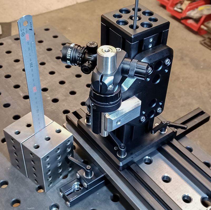
Lasers sound cool but when it comes to calibration, nothing beats optics! This reticle is clearly several orders of magnitude finer than the 1mm dot produced by the laser. Yes, I have a cathetometer.

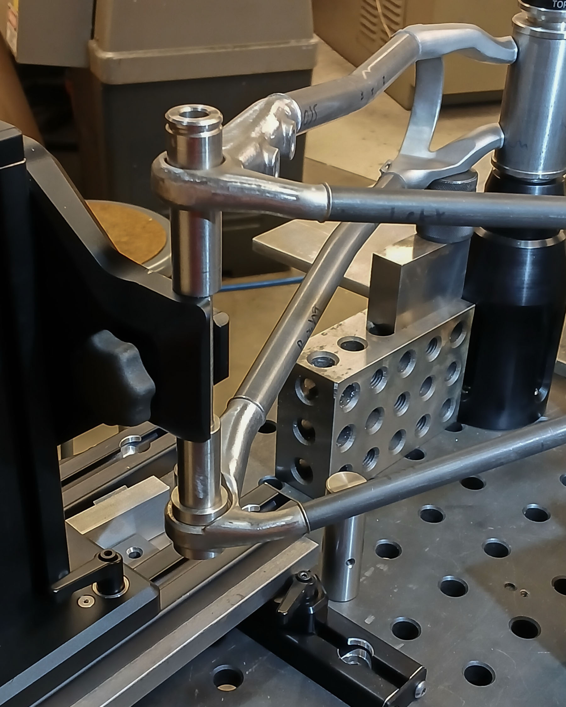
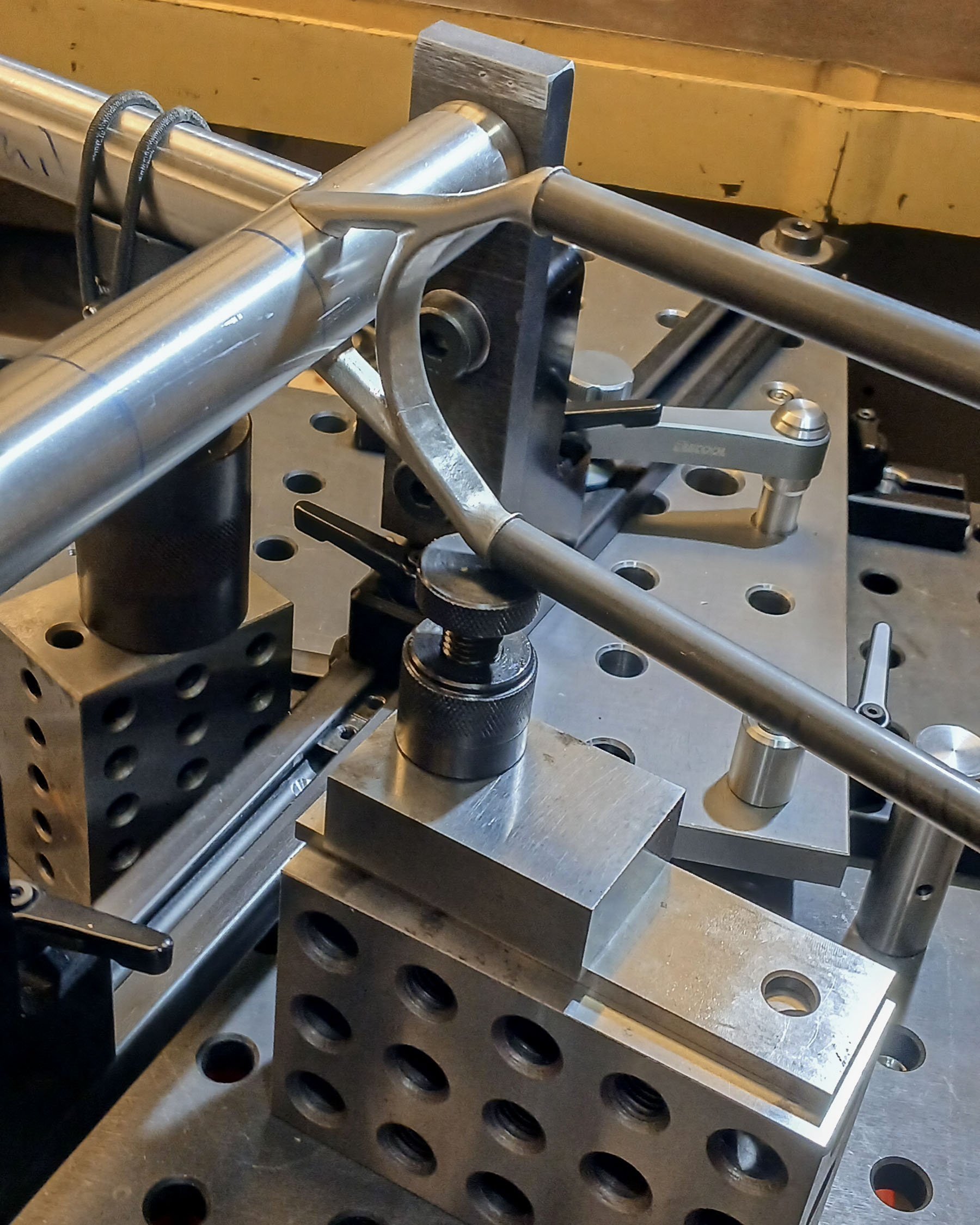
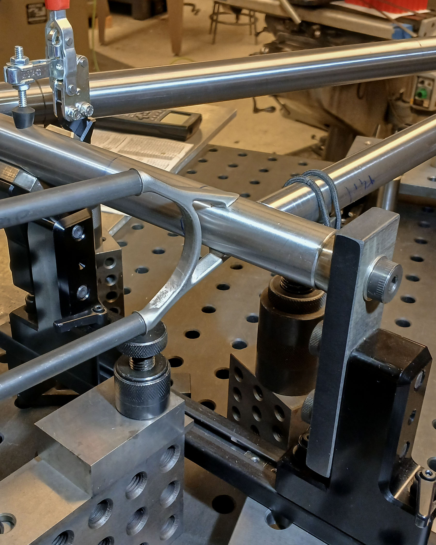
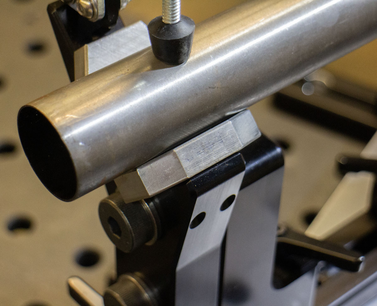
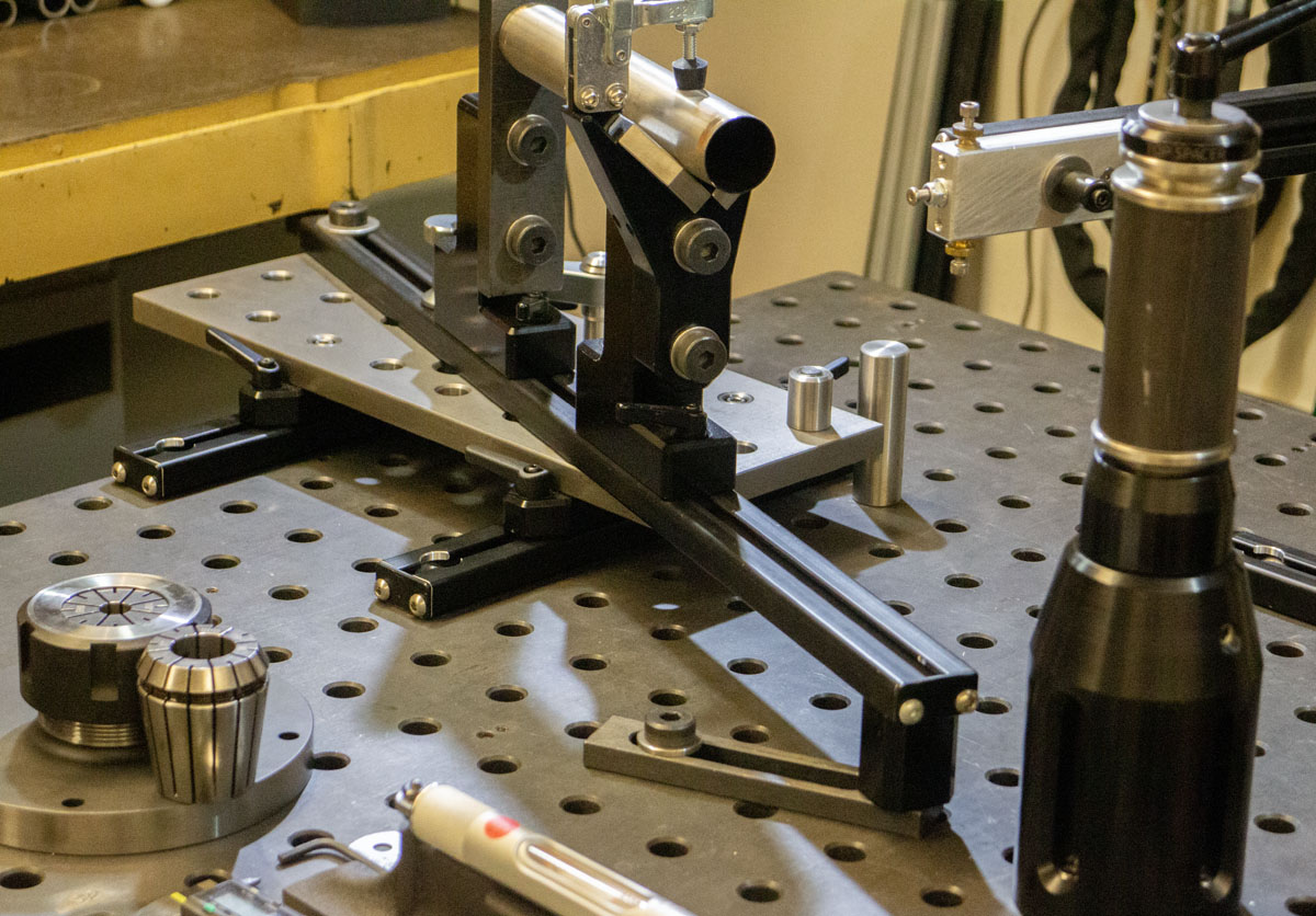
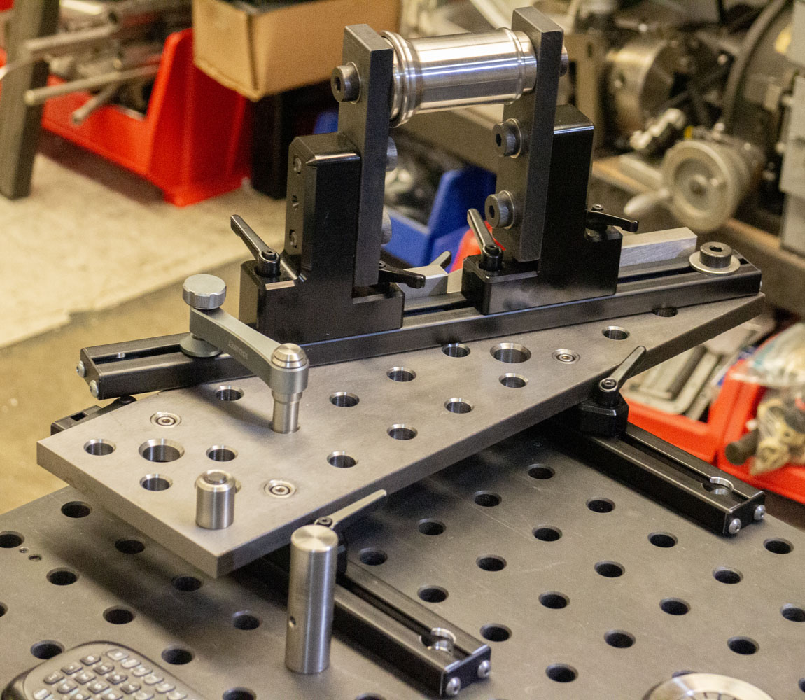
Unlike traditional frame fixtures, the seat tube placement is assisted with a sliding cradle along its axis, not just an end cone. One or more of these can be used as needed. Thus, short section and interrupted tubes can be held precisely intersecting (or floating) anywhere on the frame. The current design allows for adjustment using simple block shims for any tube diameter below 2.250″. We love range!

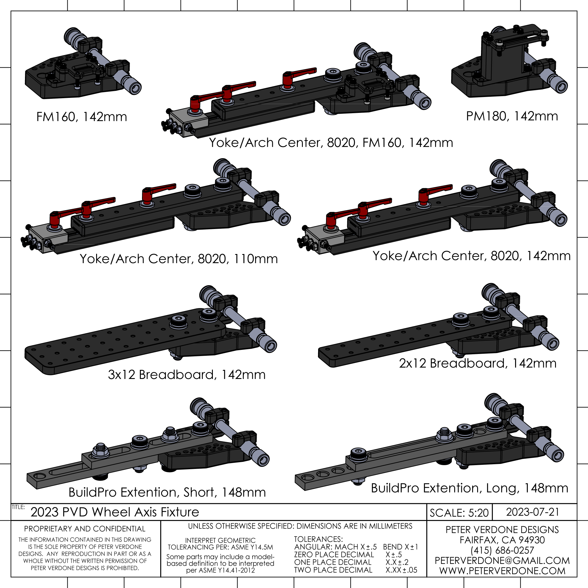
In 2023, a new dummy axle system was developed for holding dropouts designed for SRAM Full Mount and front 12/15mm thru-axle systems. These align the bores and faces to the geometry in a far more precise manner than past systems.

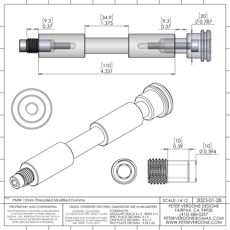
The dummy axle area of the fixture will see future development when I depart from the old Anvil style holding and move to straight shaft with a snap ring stop. I feel that this is a superior interface that is more properly kinematically constrained. It also minimizes shaft bending when the center is relieved of material.
A mock wheel tool can be placed while the frame is in the fixture. This makes it easy to confirm that the rear wheel, as referenced at the axle, is truly centered within the stays and is on plane with the center of the bicycle. The tool does so much more. It’s a brake mount tool. An auxiliary platform, it works for front and rear. Bam!
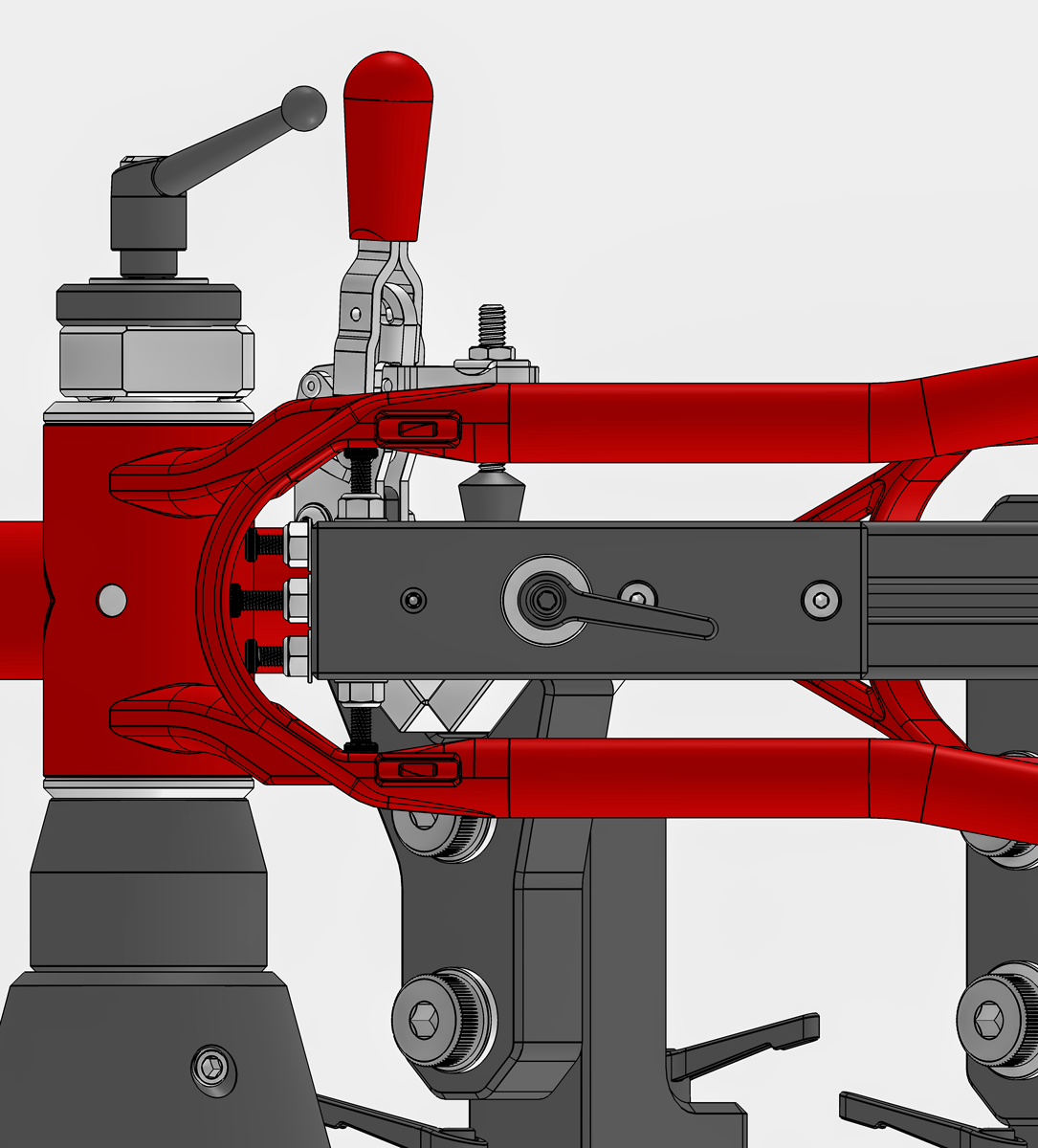
Shown here setting the yoke in position, both radially and axially.
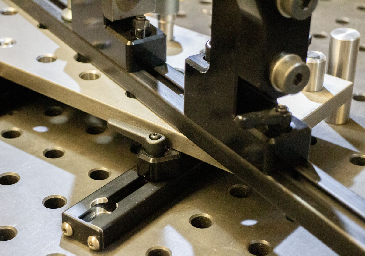
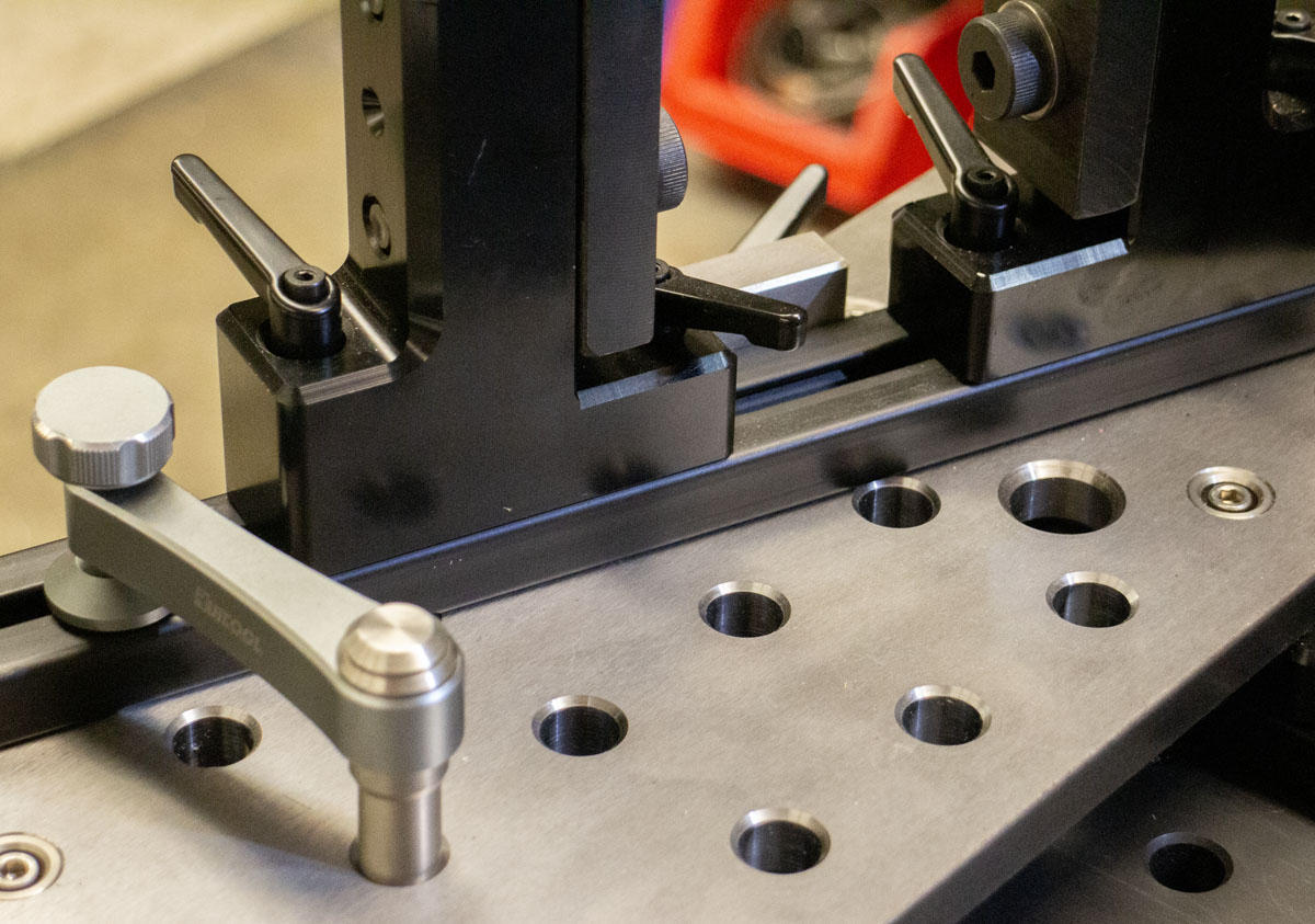
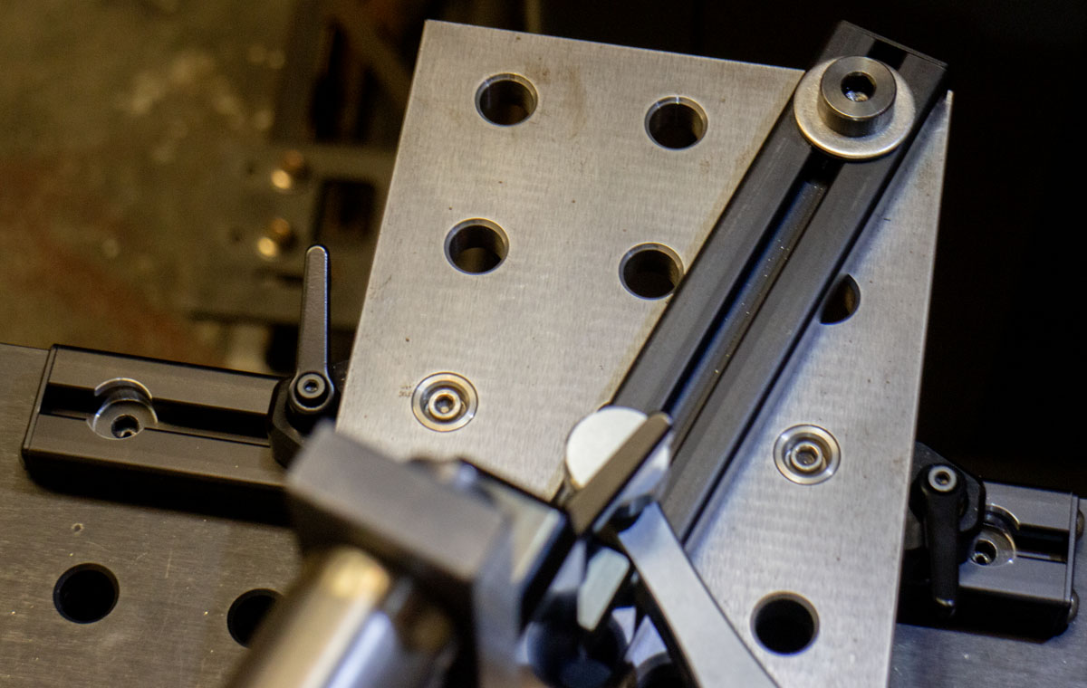
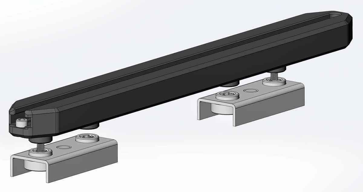
The large commodity clamps available for these fabrication tables get in the way when doing work so I developed some special low profile table clamps that make working over the table a much nicer experience. The clamp may be placed anywhere that a table hole exists with minimal space taken up over it.

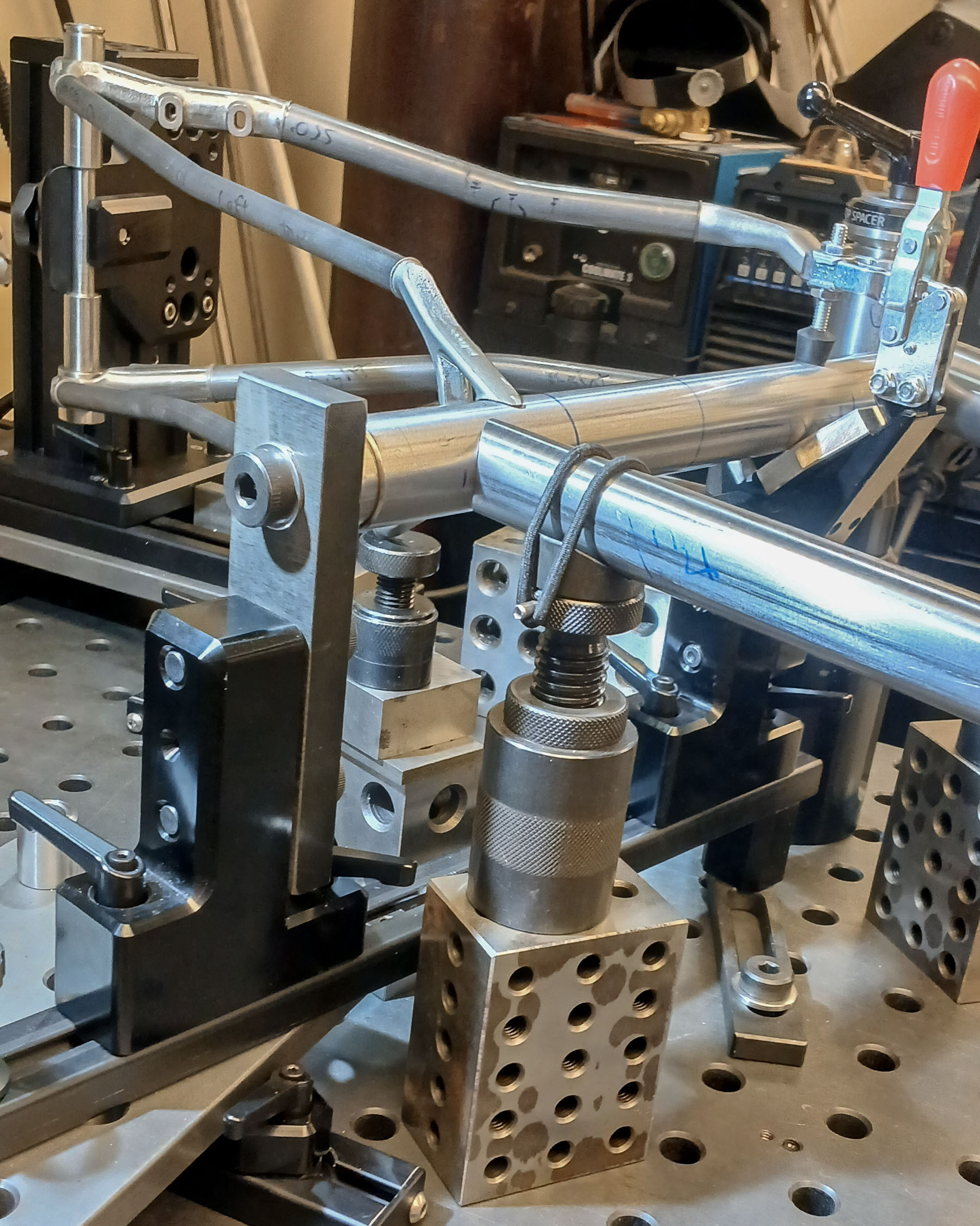
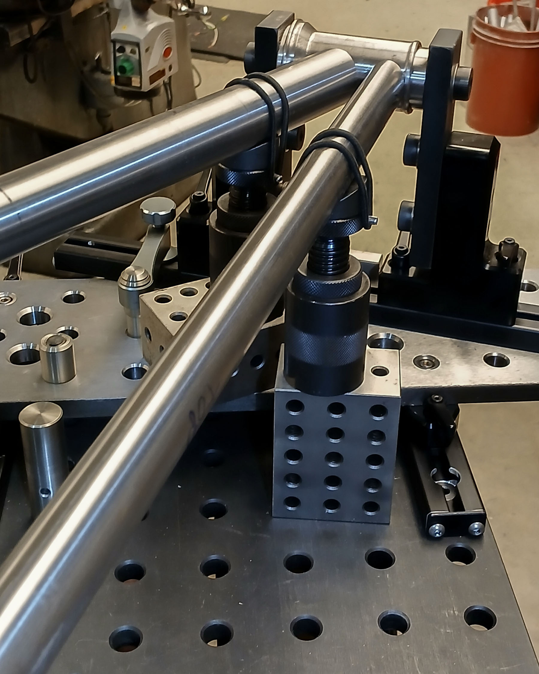
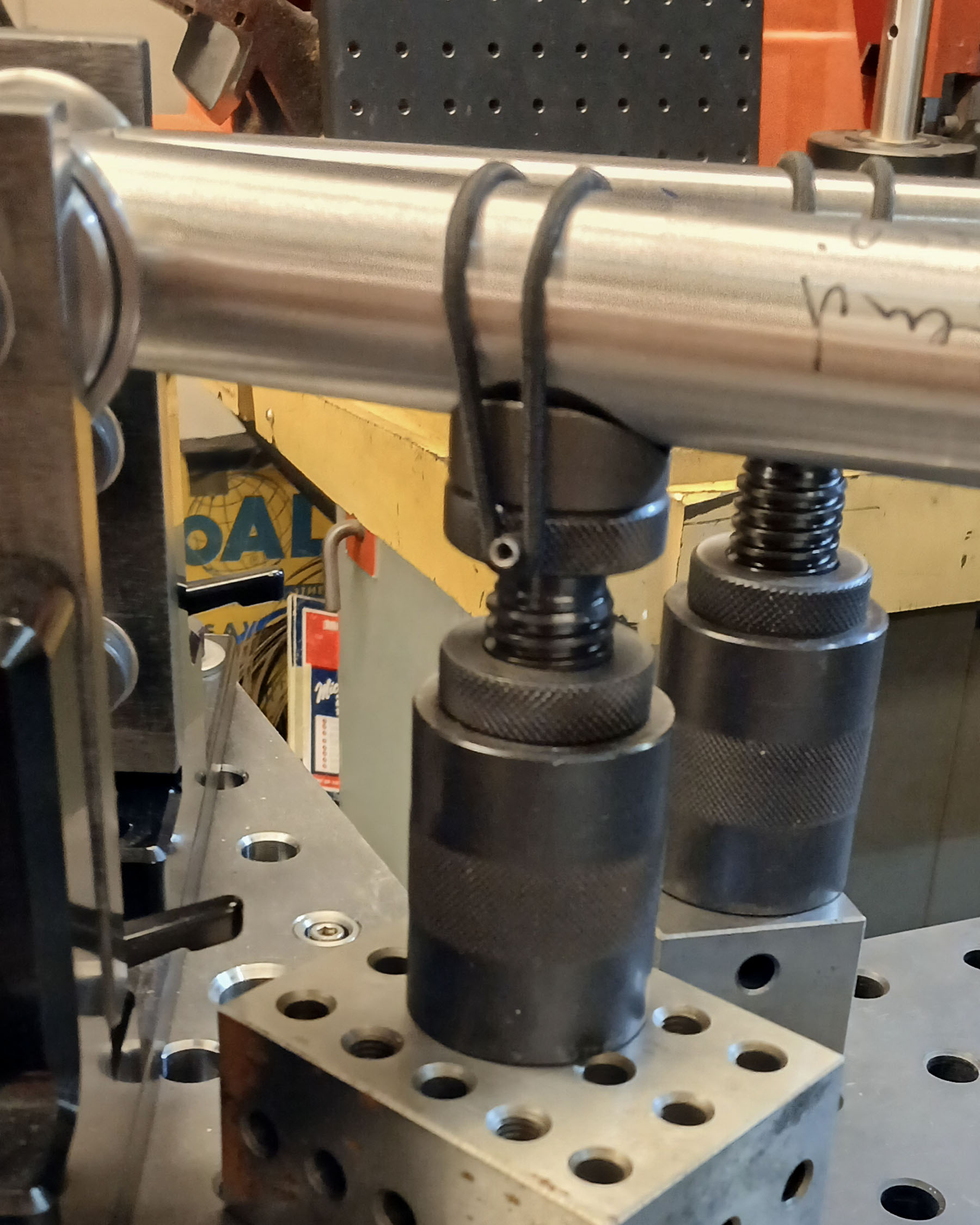
Due to the massive base that the tool is built on, many types of auxiliary tooling can be quickly or exactingly constructed. Below, vee-jacks on 2,3,4 blocks hold tubes on center with the very least amount of loading of the tube.
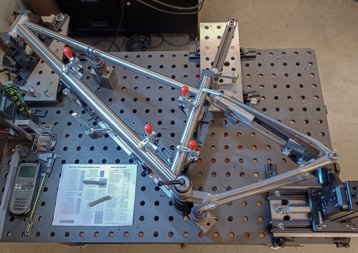
As of today, I’ve built four frames since April 2024, when this fixture was initially completed. I’ve made ongoing improvements and re-thought how I use it. It’s the fourth fixture that I’ve used personally in my shop, not to mention those we had at Fat City Cycles. It’s the fourth (fifth, actually) type that I’ve fully designed. It’s also the second fixture design that I’ve constructed in recent years. My perspective on these things is more informed than a first time YouTuber.
Samantha really is at the upper edge of design and capability. No other fixture can do so much so easily. No other fixture is as rigid or precise. Once set, I have 100% confidence that I’m getting what I plan. It feels like a real industrial factory tool but is entirely adjustable and extendable. I can’t imagine using anything else.
What shortcomings does Samantha have?
- Welding clearance – The Cyberdyne was constructed with a centerline height of 140mm. That was quite low and can be a problem. The Samantha was originally produced with a centerline of 220mm. Later that was moved to 240mm. The height is about there but I should have made it 254mm (10.0″) to agree with the raster of my table. A tiny bit more room and a better choice.
- There are times when it’s preferred to work on a frame with the center plane normal to actual earth. This may only in the final moments of tacking. If space were a huge issue in the shop, it may make more sense to hold the plate normal. In time, a nice rotisserie will be developed to allow for this but I don’t have that in place yet. Still, this is possible with planning.
- This is not a great fixture for brazed or open flame construction. I could be wrong as this isn’t my thing. This isn’t such a big deal as that hasn’t been an important method for over 40 years. Today, we arc weld or epoxy.
- It may be a challenge to develop the mathematics of the calculator for those that didn’t pass high school trigonometry or don’t have a basic understanding for how to use computer spreadsheets. Most would do well to give this a try first.
- Table level, flatness, and axis calibration are absolutely critical for the setup. Being in an environment that doesn’t ensure that would be a problem.
- The Anvil-style dummy axles need to be replaced, that is planned at a future date. A simple snap ring on a straight shaft is clearly the better way.
- You can’t buy one. Sorry, these aren’t being sold. It wouldn’t be too hard to make what is needed. Maybe one day.
Like the SKYNET and WOPR fixtures, I have a production documentation package prepared for this fixture. It does exist. I haven’t decided to make that public. I might not.