This is something interesting that came up in the shop yesterday.
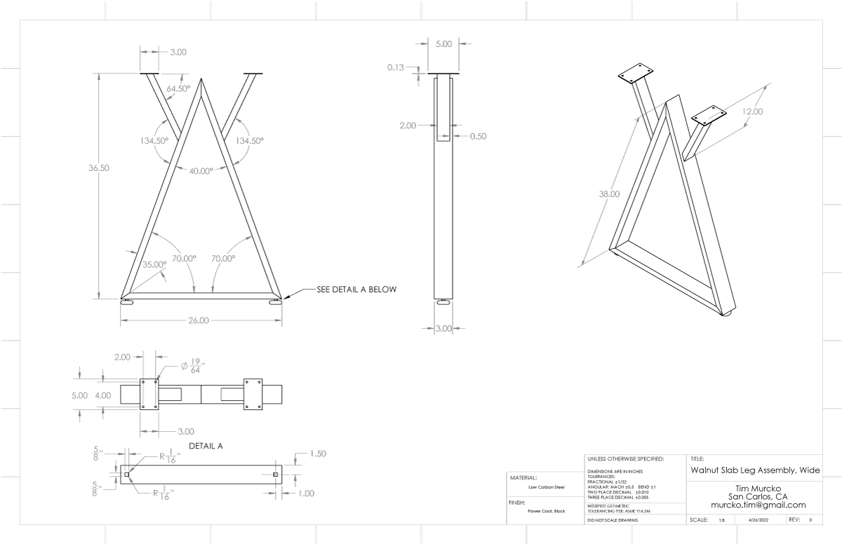
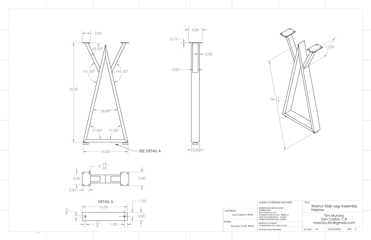
My friend, Tim Murko, has been working with wood in recent years. He’s been doing various furniture and wall art types of things. For a while, he was content with just wood and fasteners (along with some fun electronics as Tim is an electrical engineer) for his work but in a current project, he’s making a new table from a solid sawcut section of a fancy wood and that needs steel legs.
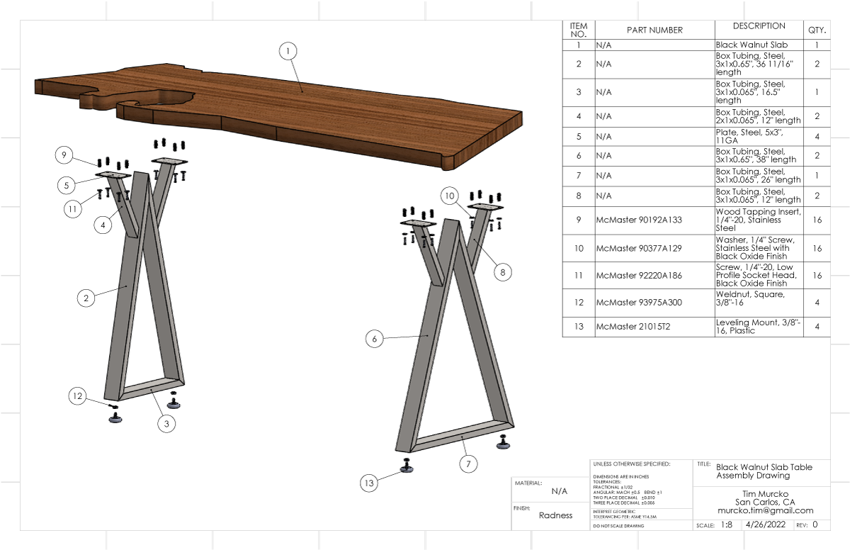
He had a design that he had worked on for a bit was interested in making. I gave him some input on evolving the design that helped refine it into something sensible economically. Then helped with details to get him into production. It’s not my kind of design but it is what he wanted. This was also a great project to get Tim initiated to using metal in design. He would also gain more experience obtaining, cutting, fixturing, and MIG welding the metal material.
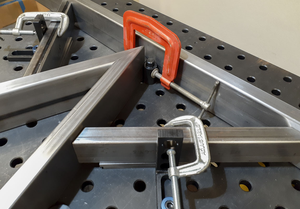
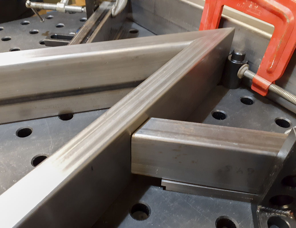
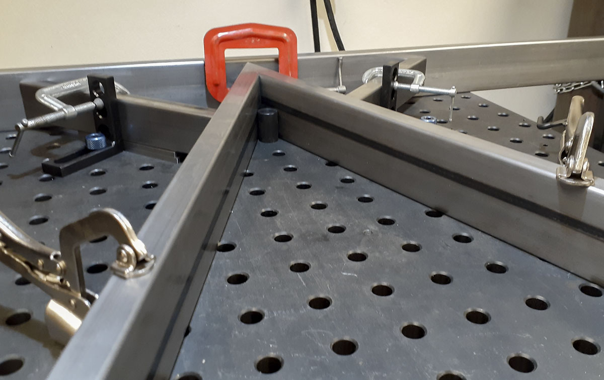
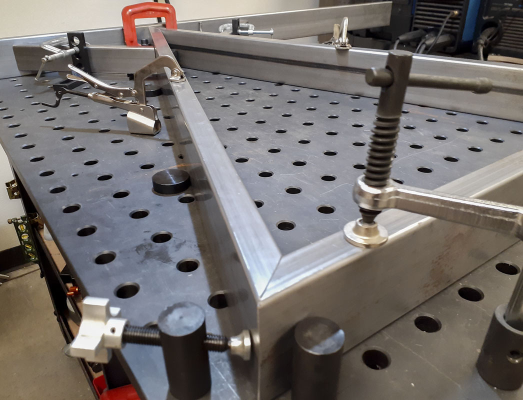
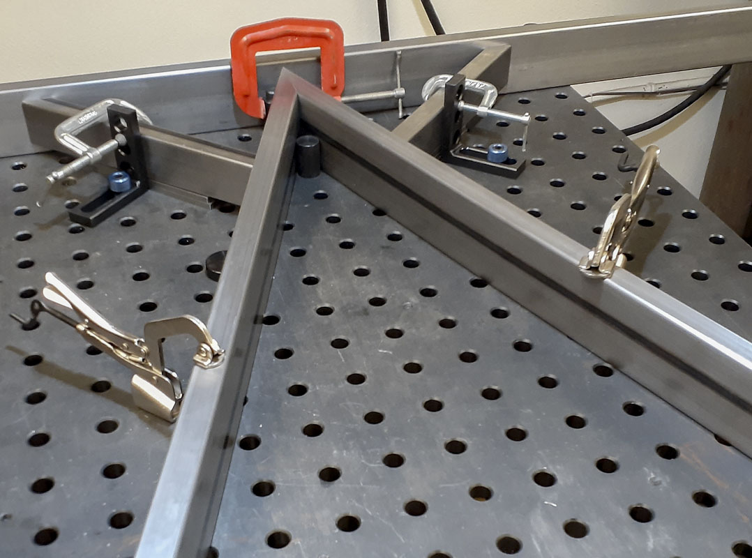
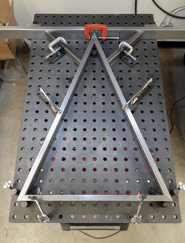
Yesterday, we were fixturing the weldment segments to the Rhino Cart raster surface. I don’t have a lot of clamps for the fixture but we found a way to get everything locked solid into place. Things look great for Tim to start welding next time we are in the shop.
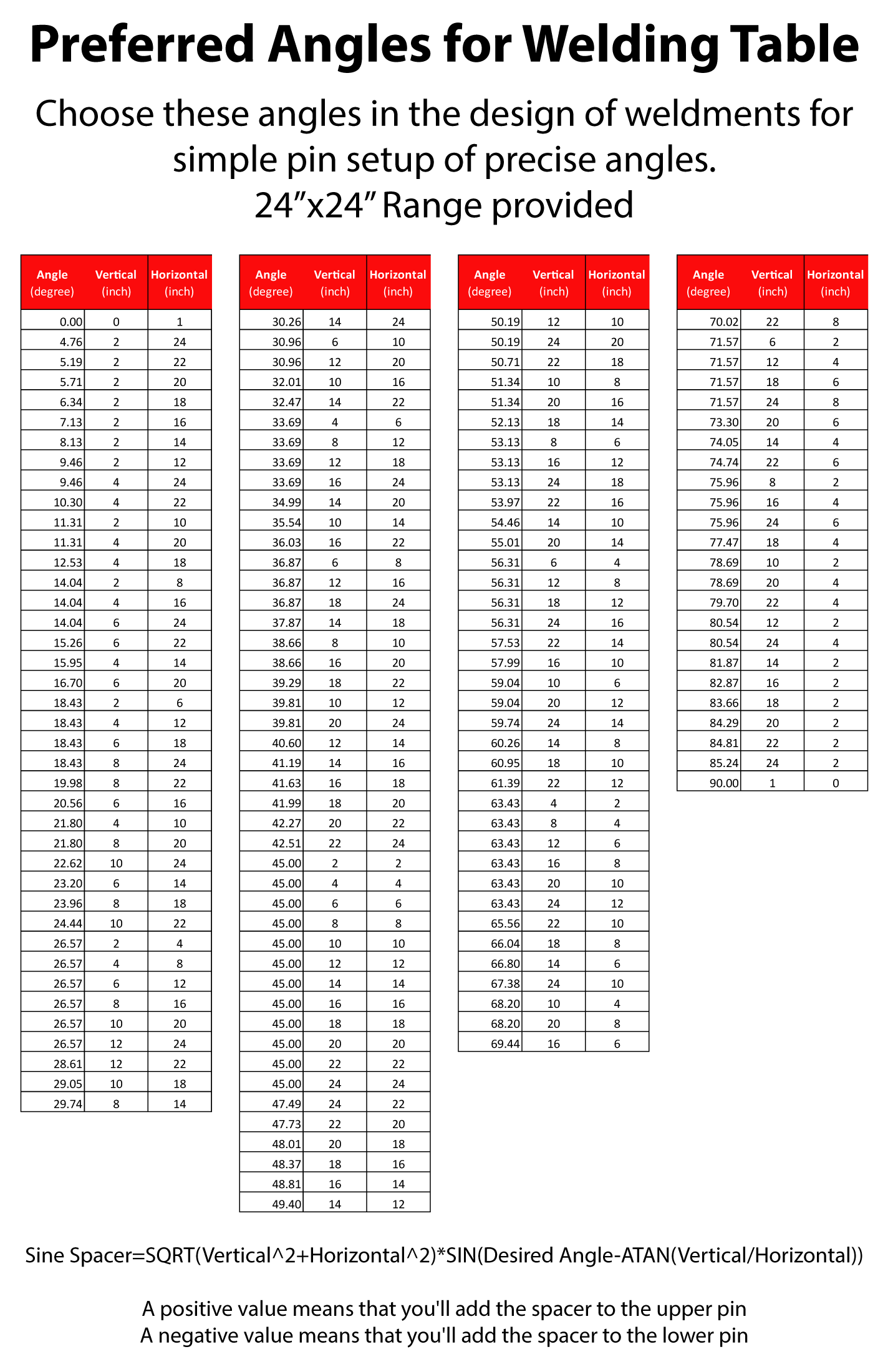
We were discussing some of the challenges and expectations for precise setup of the rectangular tubing on the table. It occurred to me that in many cases, there are particular angles that would significantly improve the precision of weldment angles that would also dramatically speed up setup. That’s a nice deal, all you’d have to do is choose certain angles if it didn’t matter otherwise.
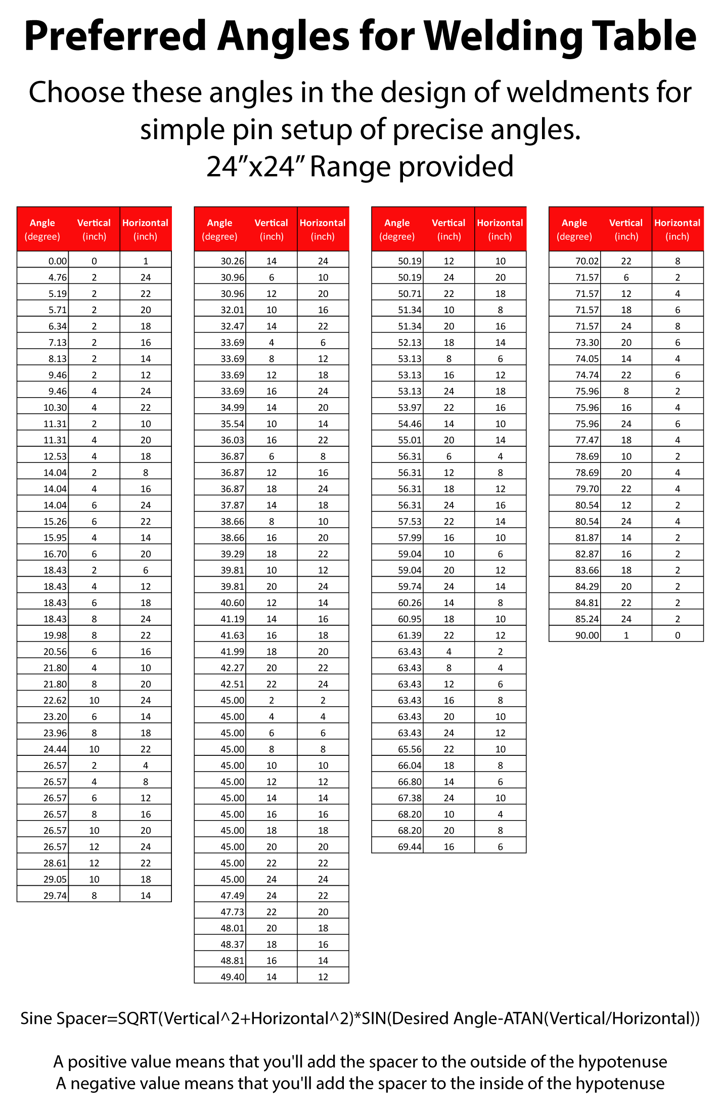
This would be done by placing equal diameter pins into specific holes as is usually done on tables like this for setup. For two holes 18″ horizontally and 24″ vertically on the raster, the centers would be at 36.87 degrees from horizonal. Since the two pins are equal in diameter, the connected tangent points on those pins would be at the same angle. Adding equal spacers to the arraignment would give very precise positioning of the beam at 35.87 degrees. It’s very simple and easy…provided you have designed for the useful angles.
I’m not suggesting that good design should be compromised when choosing an angle. I’m suggesting using these angles when an arbitrary angle could be used.
Also, if you were able to spread the pins at the greatest distance possible, I would challenge you to find a more accurate placements of the elements. Yes, weld distortion and shrinkage is a real complication in fabricated parts but that doesn’t mean that precision has no meaning. Since we are adding filler metal to the part, we can actually improve the accuracy of a part that wasn’t cut with as great a tolerance as our tables are able to achieve. An experienced fabricator is going to make good use of the concept I’m laying out here and really improve how well a part turns out in less time.
I made a quick spreadsheet of these angles. I’m going to print a poster for next to the table to remind myself and others of the concept.
It gets better…
Those values in the chart are what I’d call the ‘natural angles’. Let’s say you want a particular angle and not one of those listed. There’s a way to do that. It’s called a sine bar. This is one of the tooling principles that I use in my bicycle frame fixtures, but there I use a cosine bar. In this case, we are going to use the table to construct a sine bar on an inclined plane. That makes for an economical setup given the scale of weldments that we make.
I’m going to skip a few steps here but you’ll have to believe me, this is trigonometry. We use this all the time in the shop.
If you choose a set of pins that are somewhat close to a convenient pin location and angle for what you are doing and the close to the angle you need. You can calculate a spacer that can be added between one of the pins and the workpiece to adjust the angle to what you want.
Spacer = SQRT( Vertical^2 + Horizontal^2 ) * SIN( Desired Angle – ATAN( Vertical / Horizontal ))
- A positive value means that you’ll add the spacer to the upper pin
- A negative value means that you’ll add the spacer to the lower pin
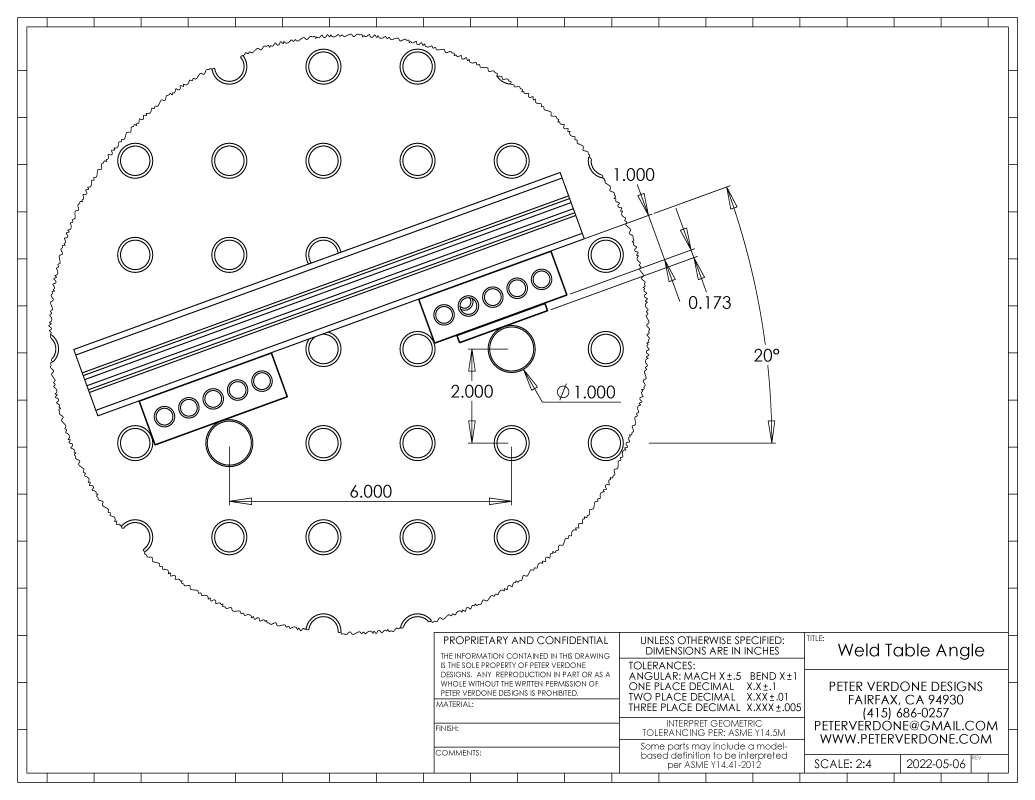
Let’s say that I want an exact 20.00 degree angle. We choose pins at 2″ (Vertical) and 6″ (Horizontal) that would otherwise give a natural angle of 18.43 degrees. This isn’t even the closest angle we have to choose from but it is reasonably close and that’s fine. What spacer would we use for one of the pins?
Spacer = SQRT( 2^2 + 6^2 ) * SIN( 20 – ( ATAN( 2 / 6 ))
Spacer = 0.173″
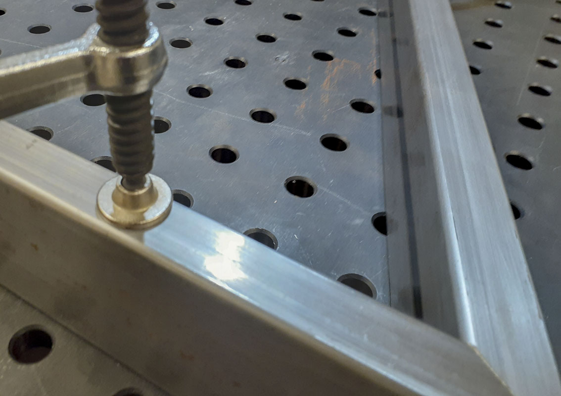
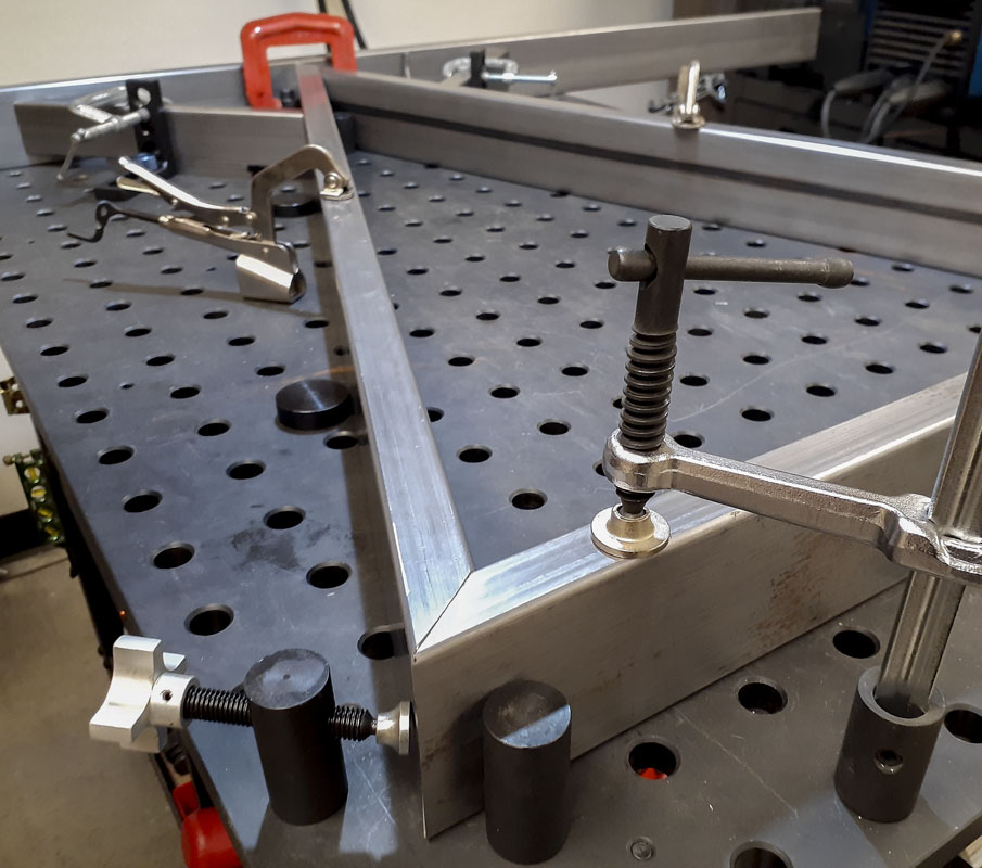
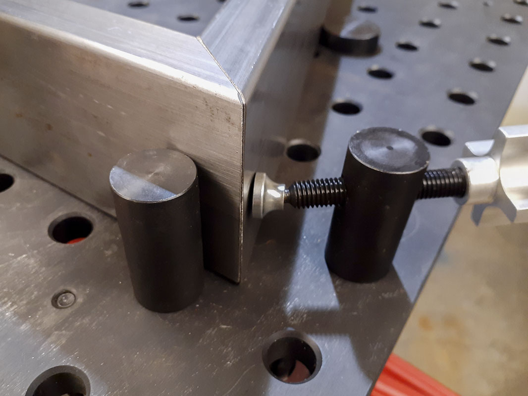
Here is a graphical demonstration of what I’m discussing. I’m showing a short section of 1575 8020 on the Rhino Cart. The pins are a pair of BuildPro T54205 – Stops. Notice that fine tuning of lateral position has been made with a pair of 1-2-3 blocks although the size could be anything as long as they are equal. The angle is made by the pin positions AND the 0.173″ spacer. This produces an ‘exact’ 20.0 degree angle.
The small shim blocks can easily constructed from a cut scrap of aluminum or built from a cheap import 36 piece Grade B gauge block set ($79.99). Because we are inclining the plane that the sine bar is built on, only very small shims are needed to get to the goal. More, several constructions can be made for any given desired angle letting you chose from pin placement, offset blocks, or shim size. It’s very flexible as anyone that has worked with these setups knows is important.
If the exact endpoints of the tube section is most important, as it usually is, some planning in a CAD environment could be done so as to know the thickness of the angle shims and the lateral spacers that would land section ends exactly where they need to land. Even if the section has a small amount of bow in it, the ends could still be very precisely placed if the reference pins are close by. Thus, an improved method for quick placement and high precision within complex constructions.
So now, any angle can be set up in a very quick and repeatable way. This leverages a huge amount of power to any work that is being performed.