I’ve been discussing disc brake fitment for at least a decade. Past blog posts are evidence of this. I’ve also been designing parts for myself and other companies that interface with disc brake systems since designing the Independent Fabrications IS dropout back in 1998(?). I’ve even been wildcatting the specifications since my beginning.
Over that time, we’ve had very chaotic and scattered information available to us. New systems are carelessly implemented with issues built into them. SRAM and Shimano publish diverging definitions. It’s been a struggle to nail anything down and then it all changes. Also, I’ve grown and developed my own understanding of these systems and engineering as a whole.
While Shimano thinks it’s a good idea to keep specifications a secret, here are some public specifications to compare from SRAM:
https://www.sram.com/globalassets/document-hierarchy/frame-fit-specifications/mtb/2024-mtb-frame-fit-specifications.pdf
https://www.sram.com/globalassets/document-hierarchy/frame-fit-specifications/road/2024-road-frame-fit-specifications.pdf
For this reason, I feel that it’s time to do another update on how we understand the common systems used today. Parameters that I used to use have changed. Since my systemization of these is far more sensible that what is published, that’s what I’ll discuss.

My math for caliper placement has been developed by reviewing all the available information, as well as measuring existing parts and manufacturer provided solid models. I have used all of these calculations in practice. I’ve made frame and fork mounts and adapters for many types of systems and bikes. My systems make sense. They work. They are extendable and parametrizable. This is a case when the wildcat wins.
Do the products of these calculations match a chosen published specification precisely, no. My premise is that my values are better. Anyone that has compared Shimano’s post mount specifications with SRAM’s will understand this. It’s chaos.
Why do I make such a claim?! Simply, I’m providing you with the formula. I’m showing you the system. They are not.
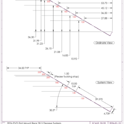
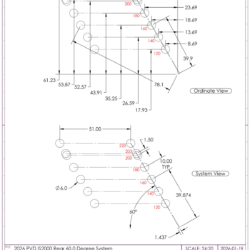
“Flat Mount R Top” = sin ( 30.5 ) * ( 39.570+ ( “Rotor Size” – 140 )/2) – cos ( 30.5 ) * 4.739
“Flat Mount R Bolt #1” = cos ( 30.5 ) * ( 39.570 + ( “Rotor Size” – 140 )/2)+ sin ( 30.5 ) * 4.739
“Flat Mount R Bolt #2” = “Flat Mount R Bolt #1” + 34mm
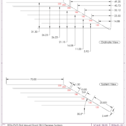
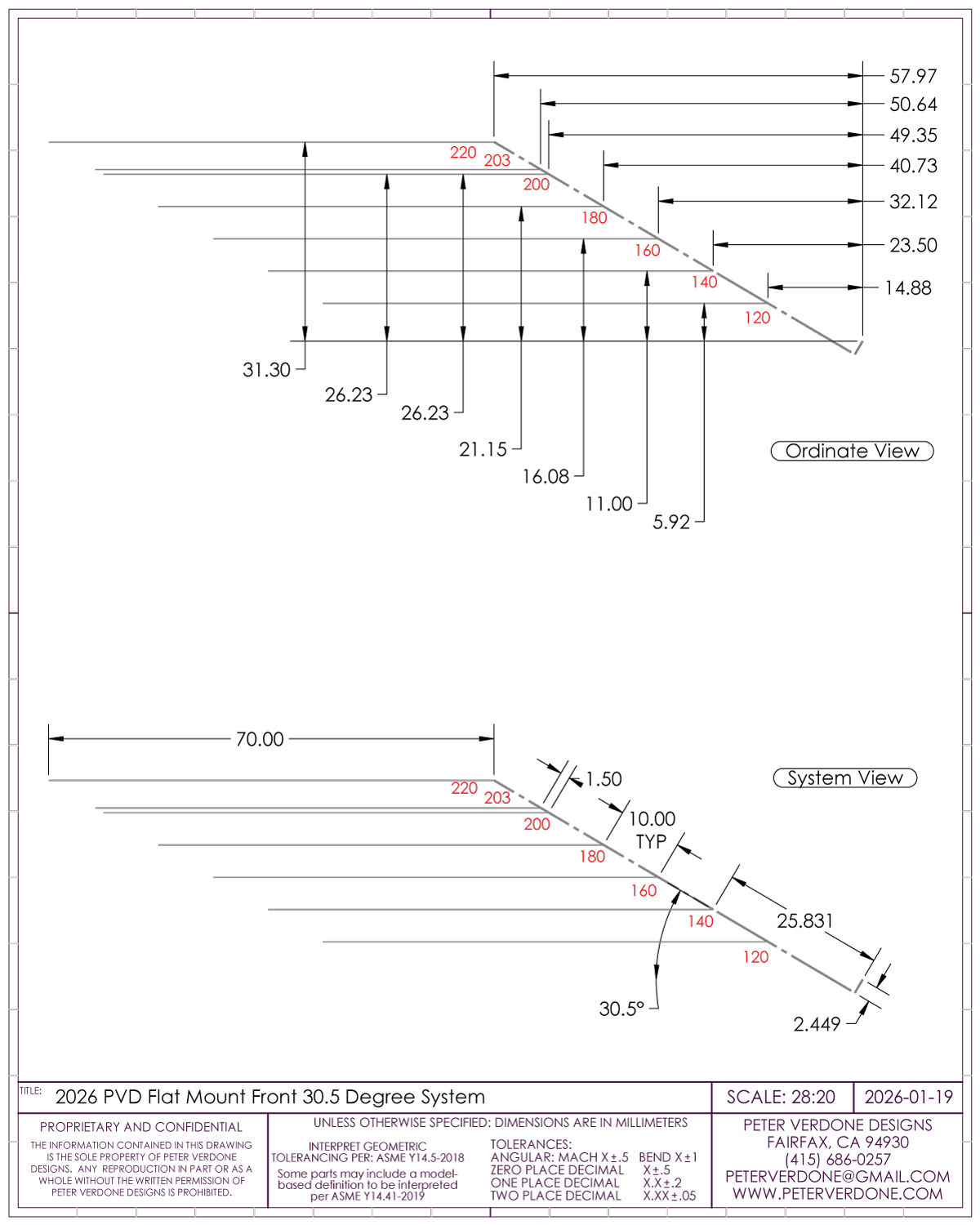
“Flat Mount F Top” = sin ( 30.5 ) * ( 25.831+ ( “Rotor Size” – 140 ) / 2 ) – cos ( 30.5 ) * 2.449
“Flat Mount F Bolt #1” = cos ( 30.5 ) * ( 25.831+ ( “Rotor Size” – 140 ) / 2 ) + sin ( 30.5 ) * 2.449
“Flat Mount F Bolt #2” = “Flat Mount F Bolt #1” + 70mm
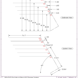
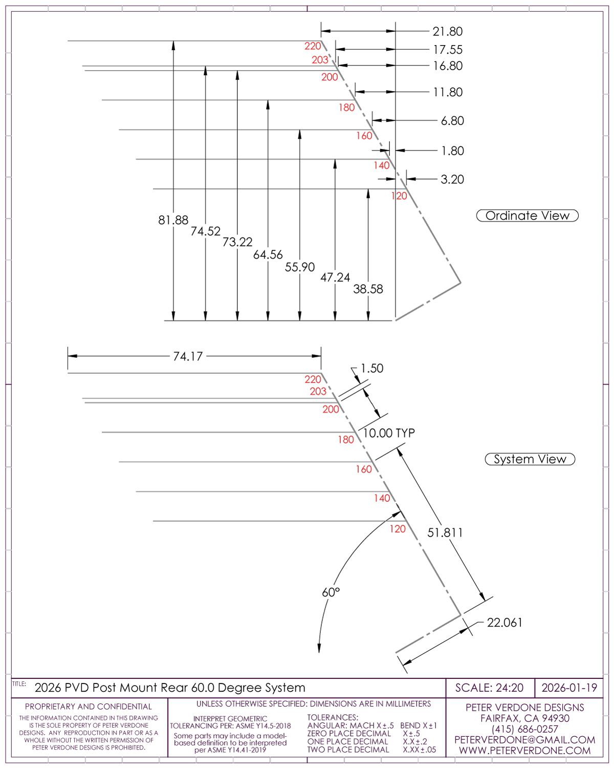
“Post Mount 60 Top” = sin ( 60.0 ) * ( 51.811 + ( “Rotor Size” – 160 ) / 2 ) + cos ( 60.0 ) * 22.061
“Post Mount 60 Bolt#1” = cos ( 60.0 ) * ( 51.811+ ( “Rotor Size” – 160 ) / 2 ) – sin ( 60.0 ) * 22.061
“Post Mount 60 Bolt#2” = “Post Mount Bolt#1” + 74.17mm
“IS2000 Height Plane” = sin ( 60.0 ) * ( 39.874 + ( “Rotor Size” – 160 ) / 2 ) + cos ( 60.0 ) * 1.437
“IS2000 Bolt#1” = cos ( 60.0 ) * ( 39.874 + ( “Rotor Size” – 160 ) / 2 ) – sin ( 60.0 ) * 1.437
“IS2000 60 Bolt#2” = “IS2000 Bolt#1” + 51.0mm
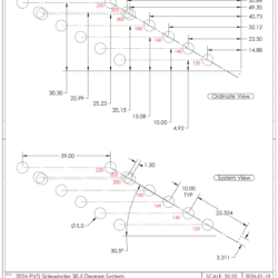
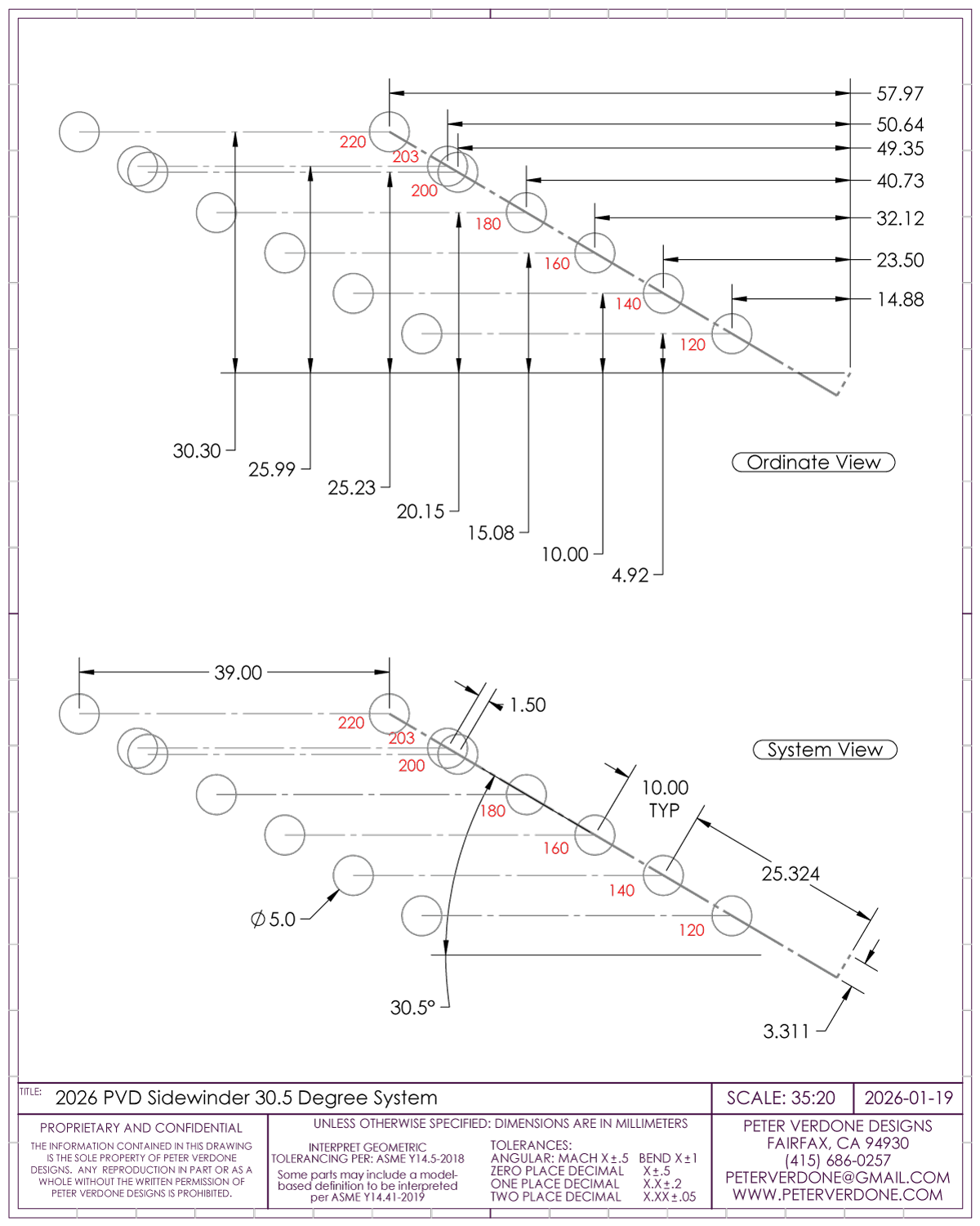
“Sidewinder Height Plane” = sin ( 30.5 ) * ( 25.324 + ( “Frame Mount Size” – 140 ) / 2 ) – cos ( 30.5 ) * 3.311
“Sidewinder Bolt #1” = cos ( 30.5 ) * ( 25.324 + ( “Frame Mount Size” – 140 ) / 2 ) + sin( 30.5 ) * 3.311
“Sidewinder Bolt #2″= “Sidewinder Bolt #1” + 39.0mm
2026-01-19 PVD Caliper Mounting Systems.pdf


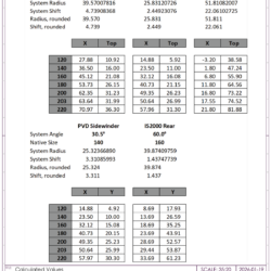
The math is done with a spreadsheet. The systemized variables may be used to eight decimal places provides the most precision. I also chose to do the math with them rounded to three decimals. This improves readability and I’ve proven that it costs almost no divergence in the second decimal of the products. You can decide.
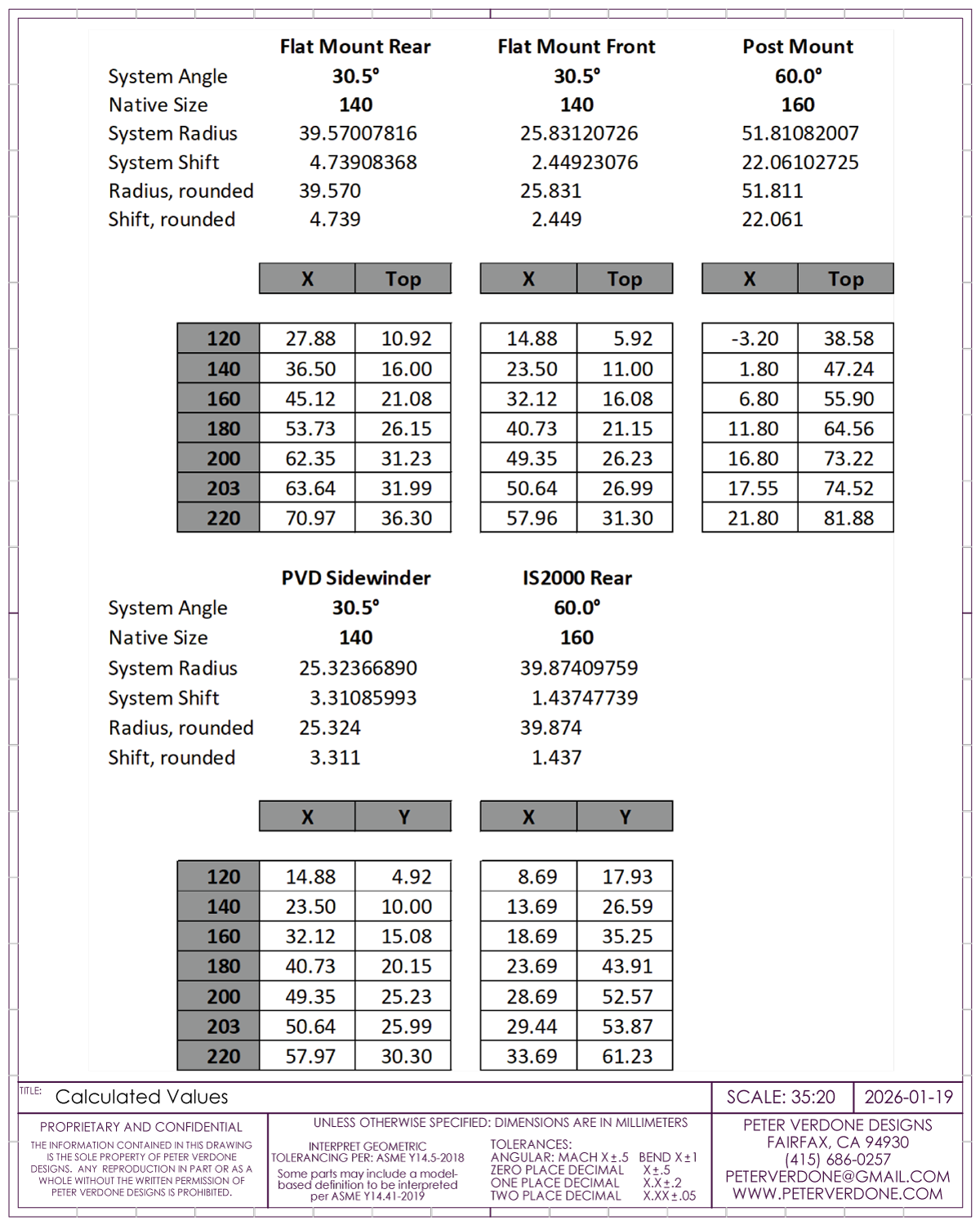
I recommend not designing around a 203mm rotor. A 200mm design can be adapted to 203mm with some 1.5mm shim washers. Not perfect but perfectly usable. This opens possibilities rather than closes them. You can’t use a 200mm rotor in a 203mm system.
Lateral positioning is very confusing in the definition. I, again, had to develop my own. The difficulty here, obviously, is that while the brake components, caliper and rotor, stay the same relative to each other, the way that the wheels clear them is different. Front and rear wheels are spaced differently (7.25mm) regarding the rotor location from the center of the wheel. This as there is more room to work with at the front wheel.
To systematize this and have it make sense, we build from the rotor. The caliper has a consistent relationship to the rotor.
“Hub Spacing”= 148mm, 142mm, 110mm, or 100mm
“Rotor Face from Center”= 55.25mm (148), 53.25 (142), 44.50 (110), 39.50 (100)
“Post Mount Screws from Inner Rotor Face”= 9.55mm
“Flat Mount Screws from Inner Rotor Face”= 12.20mm
“Sidewinder Face from Inner Rotor Face” = 20.20mm
“IS2000 Face from Inner Rotor Face” = 15.25mm Rear, 10.50mm Front
Here’s another fancy frustration saver for the equations field:
= IIF ( “Hub Spacing” = 148 , 55.25 , IIF ( “Hub Spacing” = 142 , 52.25 , IIF ( “Hub Spacing” = 110 , 44.5 , 39.5 ) ) )
This will allow for the return of the rotor location given the 4 most popular hub spacings. I can add more as time goes by or my directions change.
The lateral values that I use are based on the Shimano Centerlock specification (10.5mm (F) & 18.75mm (R)) for the inner face of the rotor to the hub end. I believe that the Centerlock is the preferred universal in the current era. The Shimano specification for 6-bolt is 10.25mm (F) & 18.25mm (R) from to the hub end. This shouldn’t be the case but is, like many issues in bike design. Thus, calculations specifically for 6-bolt would be 0.25mm (F) and 0.50mm (R) outboard from what I’ve provided.
Different rotor thickness can inform the builder as well, Shimano is based on 1.75mm. Most current setups are using 2.0mm thick rotors. Ebikes go even thicker. For this reason, I hope that we see some clarification on lateral positioning.
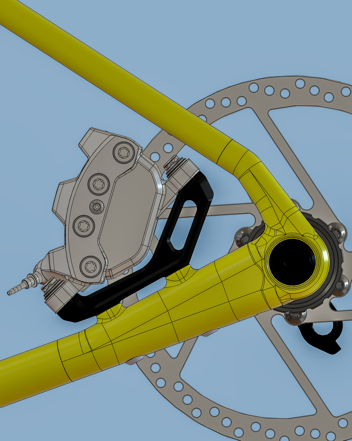
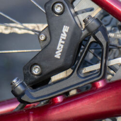
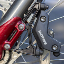
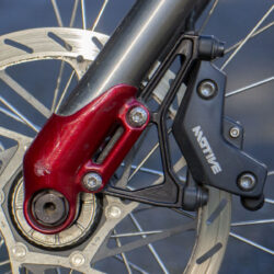
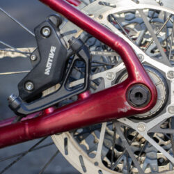
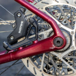
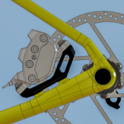
Shown for reference is my old PVD Stepdown mount. While this is antiquated in the age of flat mount on the chain stay, it was a great tool for producing very elegant dropout areas on custom frames. I could review the method for this in the current era but that isn’t worth the investment.