I’ve been working to develop new tools in my shop that expand my capacity in novel ways. As I look at my goals and future projects, hydraulic power is an area of the shop that hasn’t been exploited well but should be. I believe that most would say the same. If you don’t work in certain industries or processes, hydraulics can be strange and a mystery. It’s also got a heftier price tag to start than some other systems.
Keeping myself open to what we have these tools for is important. What problems are they best at solving? What do they do better than anything else? If I have an open mind, I will see more than I did the day before.
Hydraulics are awesome. They are some of the strongest of tools we have. Most common are hydraulic jacks and presses. You can lift or crush almost anything with them. Less common are tooling that requires significant leverage or rotational force where hydraulic rams and motors are integrated.
I’m particularly attracted to using a hydraulic motor for a new bender project. Also, some forming tools. I’d really like to start working with sheet metal more than I currently do. Some firearms projects will require this.
Having a system that provides several hydraulic circuits to be configured in different ways would provide value. I could have a ram on one circuit, a motor on another, and a press on another. Each can have separate controls, speeds, and pressures. This is a wise goal.
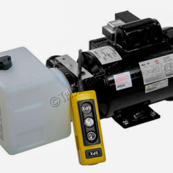
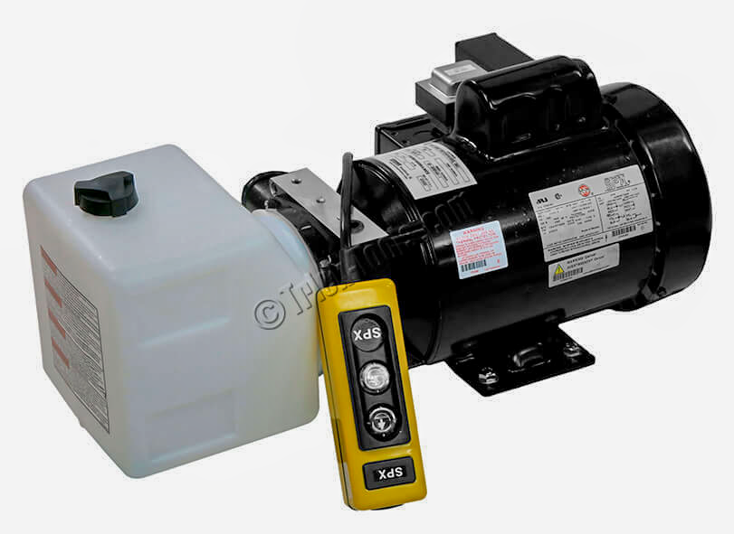
At the heart of any hydraulic system is the hydraulic power unit (HPU). The motor spins and the pump draws from the tank and creates flow. These units can be very expensive and have varying capacities.
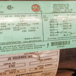
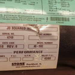
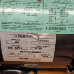
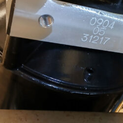
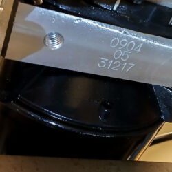
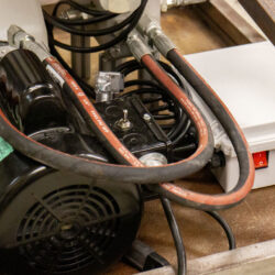
Lucky for me, I had a HPU in the shop. It’s part of my JD2/32 tube and pipe bender. The bender has a nice HPU. An SPX Power Team, 4,300 psi, Electric/Hydraulic Pump with pendant remote. The motor is 20 amp and displaces 1.5 GPM to 2.1 GPM. ISO 46 hydraulic fluid.

While the HPU is nice, the plumbing that it came with eliminates options. It is configured specifically to operate one single-acting ram. I will need to change that.
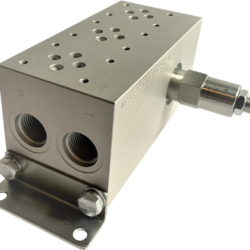
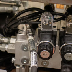
The unit had come with a Stone KB11 manifold to the D03 directional control valve. This would have been an easy connection to change but the manifold seemed to have been modified by SPX to have a bypass in one of the circuits. This made the manifold useless for anything but the initial system configuration.
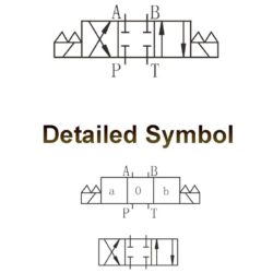
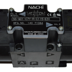
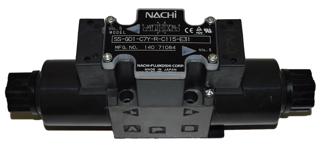
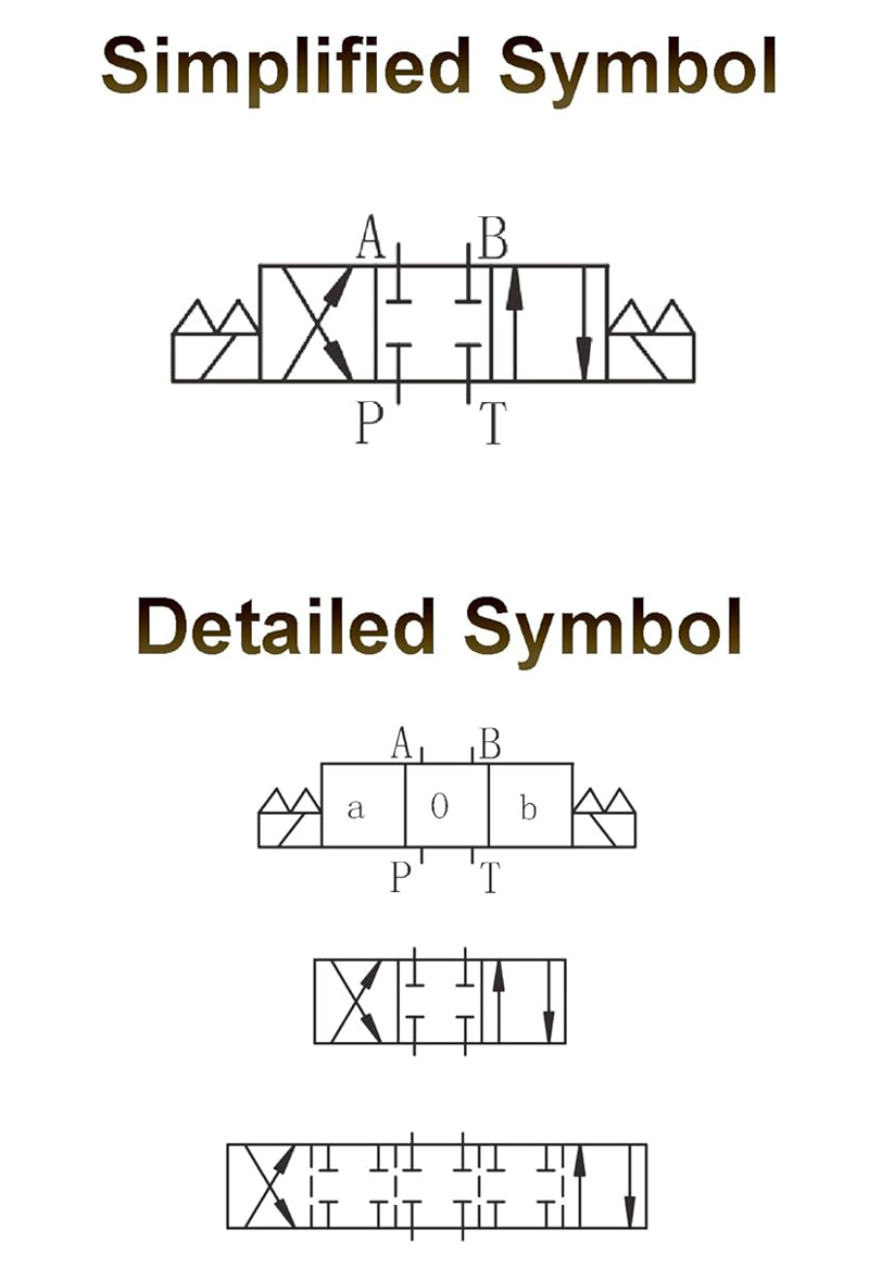
A fairly nice Japanese directional control valve was in place. A Nachi Hydraulics SS-G01-C7Y-R-C115-E31. The problem was the spool. Note that when the valve is inactive, pump diverts directly to tank. That makes this valve useless in a system where other circuits are used from the same source as there would be no pressure in the common lines.
So, both the manifold and the control valve were unusable with anything but the initial configuration. This is frustrating.
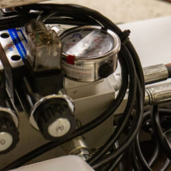
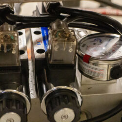
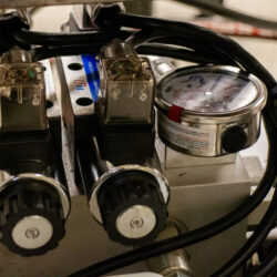
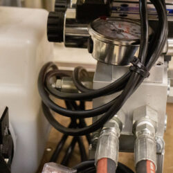
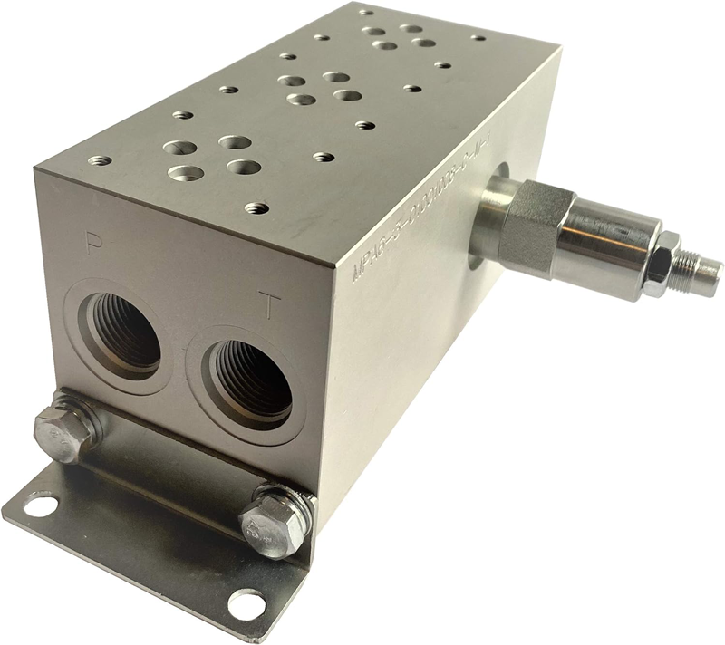
To remedy this, I chose to skip a manifold on top of the pump and run a pair of lines directly to a remote manifold with 3 stations. It’s aluminum, D03 NG6 Cetop 3 subplate pattern, with Pressure Relief valve, FluidHaus MPA6-3-O10O10O8-C-M-1. The manifold’s 300-3,000 psi pressure relief valve (C-10-2) give some safe control outside of the relief in the 4,300 psi (highest) valve in the HPU.
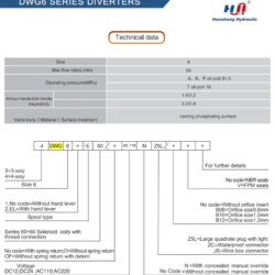
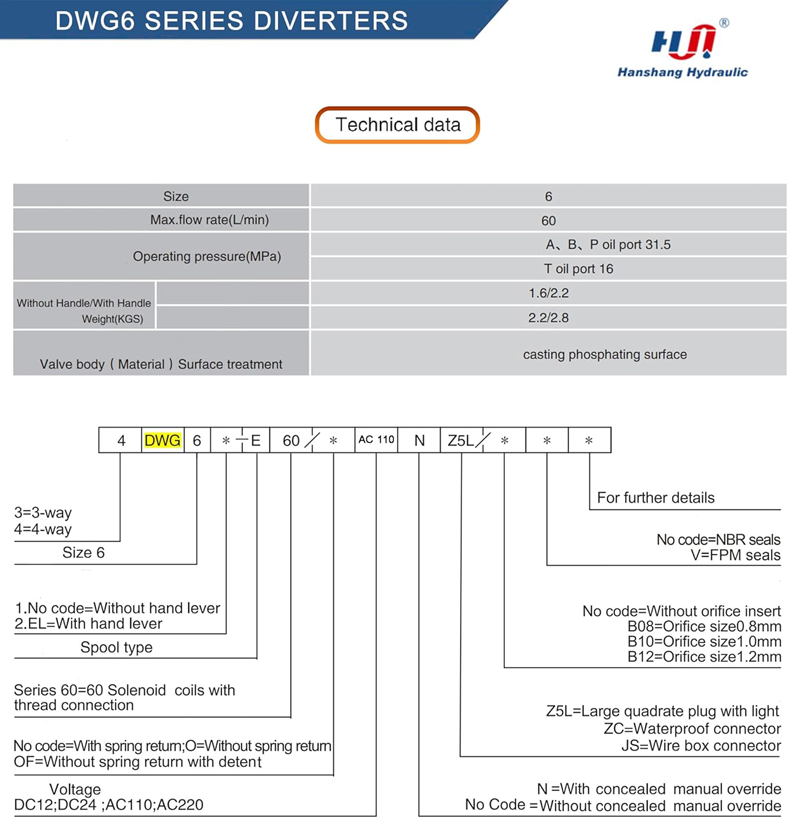
I purchased a couple of cheap Chinese 120v AC directional control valves that allowed independent flow control. Amazon had some Hanshang Hydraulic DWG6 valves for $135 each. I liked the electrical connections of the original valve but chose to use a valve with DIN 43650 Type-A, 3 prong plug connections. This seems to be the most universal type so will offer common repair parts.
Hydraulic Valve Directional Control Electric Solenoid, 3-Position, 4-Ports, 2-Pin, 4-Way (D03, NG6, Size 6, AC 110V), Hanshang Hydraulic
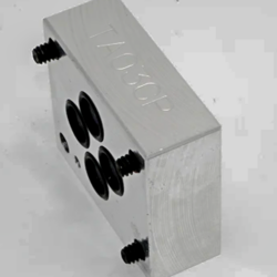
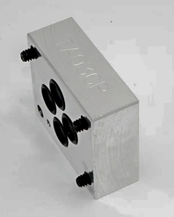
Since I’m being cheap (for now), I’m only using 2 of the 3 stations of the manifold. I needed a blanking plate for the third. It is a TA03CP, D03 aluminum cover plate from Triton Services and a copy of Daman AD03CPP but a lot cheaper.
Various fittings and hose were purchased from Titan Hydraulics. They are a nice supplier for these parts at decent prices. I also have high pressure couplers that I discussed in 2018. Although I’m thinking about moving to 3/8″ flat face ISO 16028 couplers
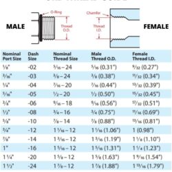
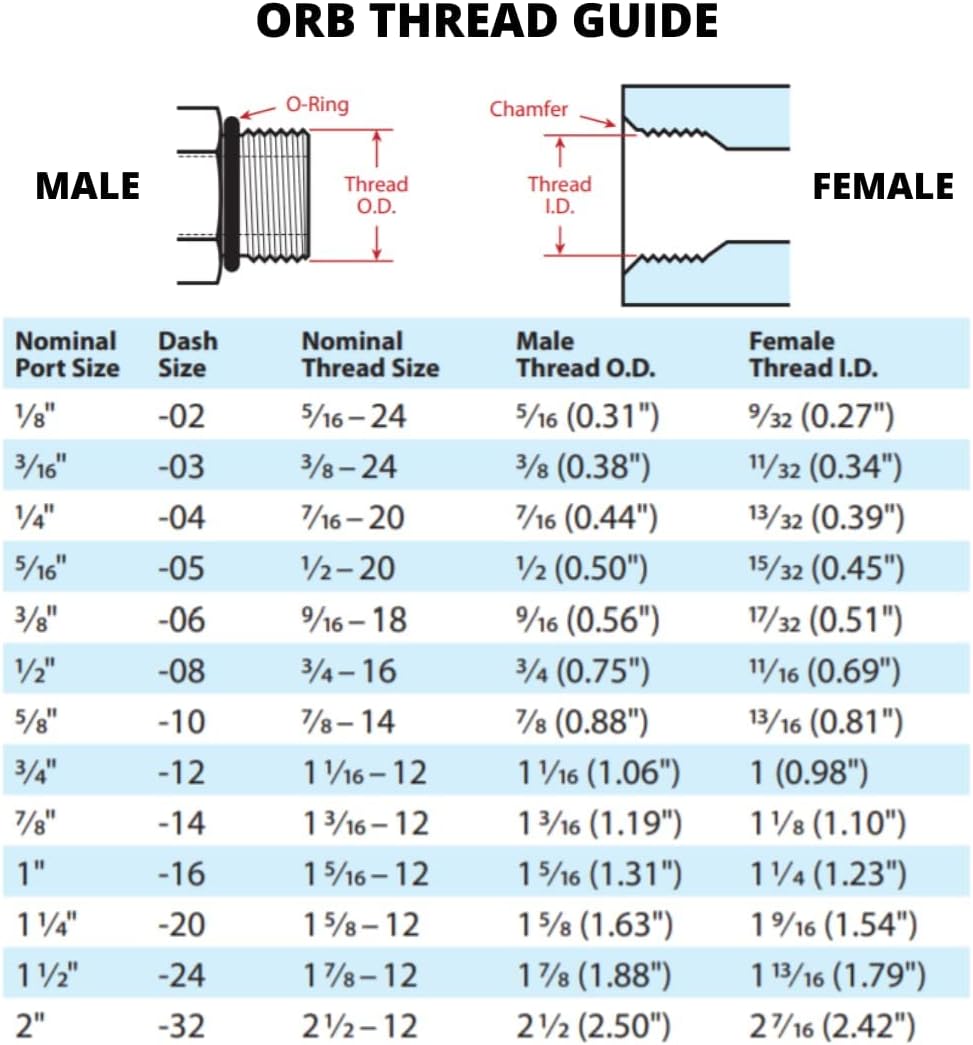
ORB threads are used a lot in these systems. Also NPTF (National Pipe Taper Fuel, ASME B1. 20.3). Make sure you understand these before ordering parts.
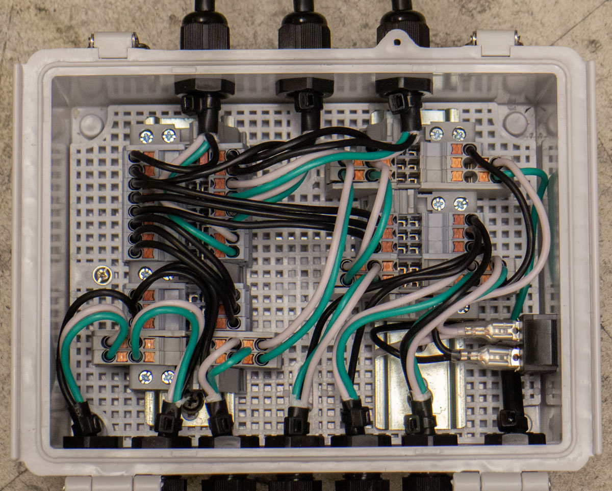
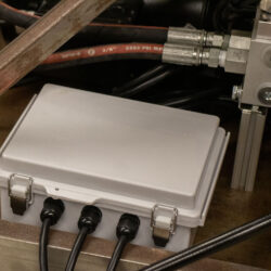
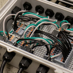
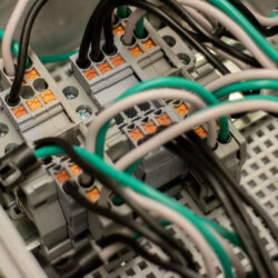
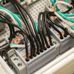
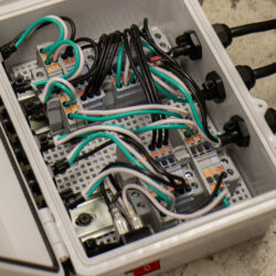
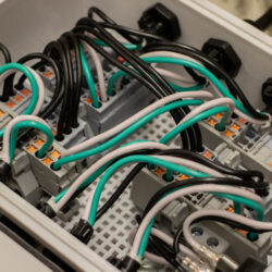
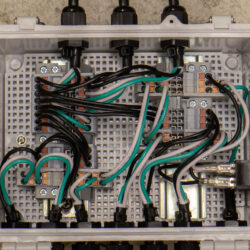
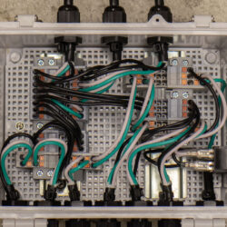
With the hydraulics taken care of, the electricals needed to be configured. This would be an industrial control panel style box as a junction for the systems wires. Laying it out this way makes trouble shooting and reconfiguring very easy and clear. DIN rails are simply the best!
I have to admit to being a noob regarding designing and assembling industrial control panels. I learned a lot when I made my CNC controller box project but I’m certainly not great at it. I am starting to figure out better and cheaper ways of getting good results. Working without a mentor slows this down. Strange to work adjacent to an electrical engineering school program and still have nobody to get guidance from.
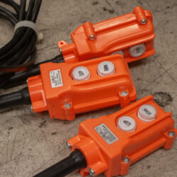
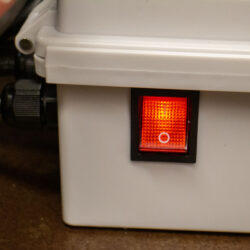
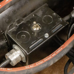
I rewired the Stone/SPX HPU junction box to have a 120v AC NEMA 5-15 receptacle output instead of a control pendant. This gives me a power plug for the electric control. It can be connected through the power unit electrics or an independent source of electricity. I regret not giving the ICP box a C13 male connection for power. Maybe next time.
DIN 43650 Type-A 3 Prong Plug for Solenoid Valve Coils (AC 110V 220V)
COB-61 Crane Pendant Control
IP67 Waterproof Junction Box, ABS Plastic, 210x160x100
Sipun ST2 Feed Through Push In Terminal Block, ST2-2.5
Sipun ST2 Double level Terminal Block, ST2-2.5/2-2
Sipun ST2 2-IN-2-OUT Terminal Block, ST2-2.5/2X2
35mm DIN rail, Steel
Illuminated 4 Pin ON-OFF DPST 250VAC/30A Rocker Switch KCD2-201N-B-R12V (Red)
PG9 Cable Gland
8mm/12mm silicon tubing
16/3 SJTW cord
Using steel DIN rail is a lesson that I had earlier. Never use aluminum rail unless you have a very good reason. That material is too lightweight to have the durability necessary in these systems. This is real.
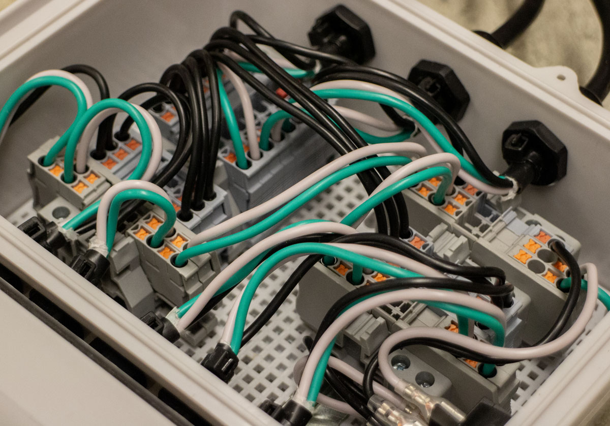
I had initially attempted to wire the system using 14/4 SJOOW cord and similarly sized ferrules. This to theoretically match the strain relief diameter of the coil plug, optional pendant wiring, and have a nice heavy wire gauge for excessive amperage in the line. The specification for the 2.5mm terminal blocks said 14AWG wire was usable. The crimping had been done with a hex crimp. This proved to be highly problematic. While the crimped end fit into the terminal blocks fine, the wire locking system failed to function, so the wire would pull out easily. I tried a trapezoidal crimp to help the wire locking but that didn’t help. More, the OD of the wire sheath was slightly oversized making strain relief routing and wiring the DIN plugs challenging. Eventually, I switched to a 16/3 SJTW cord and a trapezoidal crimp which fixed all the retention issues. The 8.3mm OD worked much nicer with the strain reliefs. While the terminal blocks are supposedly rated for 14AWG, I’m going to consider 16AWG the maximum wire to use for the screwless terminal block systems.
Now I can start designing tools that have an established power source.
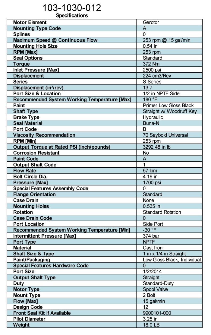
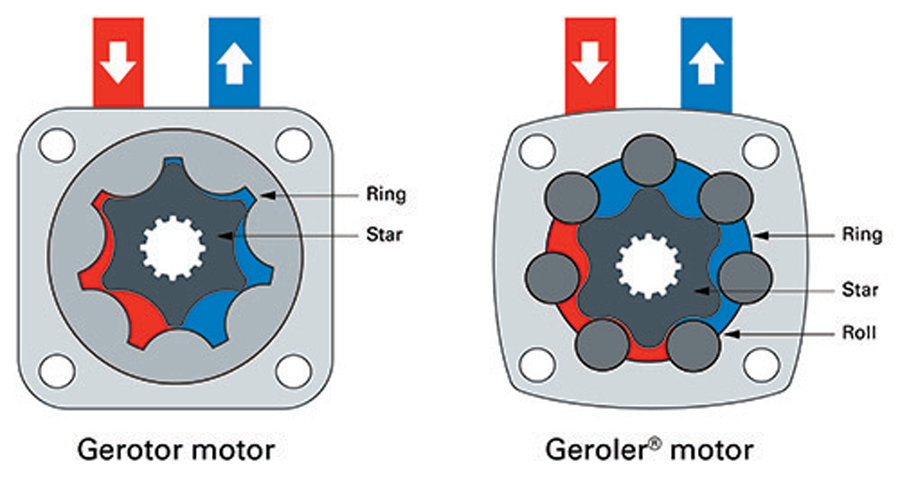
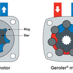
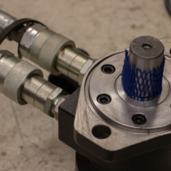
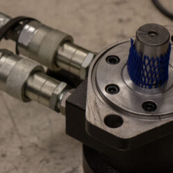
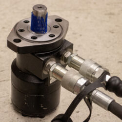
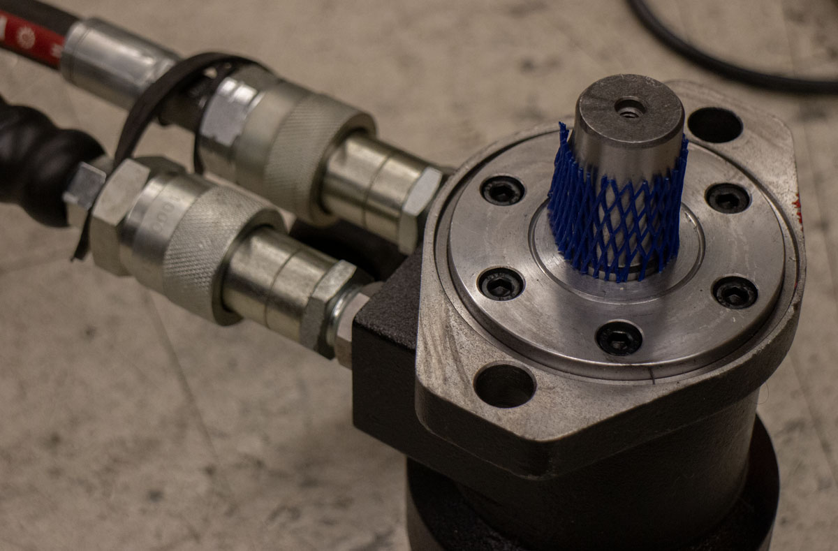
I had purchased one of the cheapest hydraulic motors that I could find on Amazon about a year ago. It’s a knock off of an Eaton Char-Lynn (Danfoss) S Series 103-1030-012 motor. This is a motor used in a wide array of industrial and agricultural equipment. The size is 225, which refers to the fluid displacement of 224 cm^3. It’s a Cast Iron Low Speed, High Torque (LSHT) Spool Gerotor motor with serious output. 372 Nm!! 275 ft-lb!! That’s crazy for such a small package.