Now that I’ve got my laser marking system up and running, it’s time to fit up a rotary attachment for doing radial marking. This is exciting as so many parts that I produce and encounter have some sort of cylindrical profile. This is an easy expenditure to make this far into the investment.
Some marking machines on the market are sold at a premium with a rotary device all sorted but the way that they go about it isn’t worth the cost added, in my opinion. There are a few off the shelf aftermarket rotary kits available but I wasn’t impressed by what I saw. They all seemed very small (50 & 80mm) and limited in alignment. It’s probably the machinist in me but I want to be ready for all kinds of situations in the future.
The first step in the process was to figure out the structure of the axis and motor. The foundation for all of this is the spindle and what it can hold. Then, how it moves, then how it’s controlled.
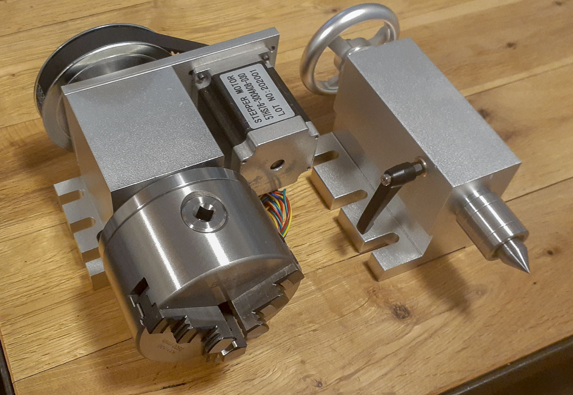
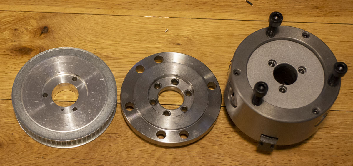
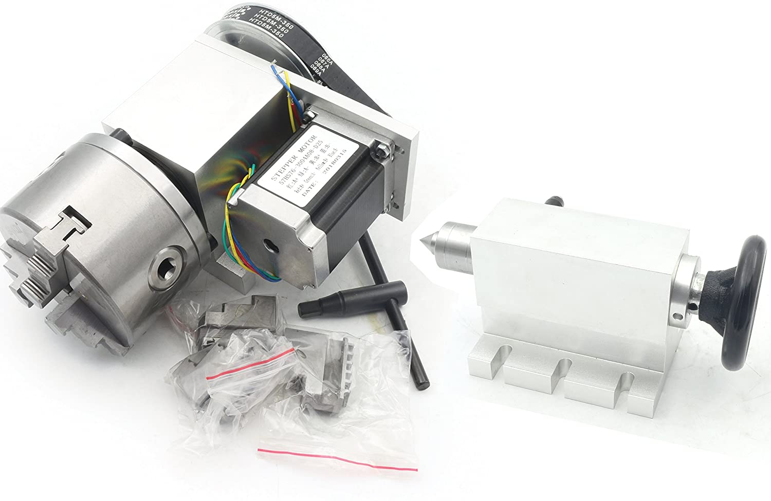
Scanning the market, I ended up looking mostly at the cheap router setups. The Rattm K11-100mm with offset motor and 1/6th gear reduction (1/3rd in listing) looked to have a decent size chuck in a compact package. It runs at a 65mm center height. The live center in the kit is nice to have on hand but I expect to keep that to the side most of the time. It’s generally used on a router or small CNC systems built around Mach3 so I can use this in another tool if I choose at some point. It’s definitely overkill for laser engraving but overkill is usually a good thing in a precision environment. It’s a $325 unit which is within the range of these types of devices for laser but significantly more capable.
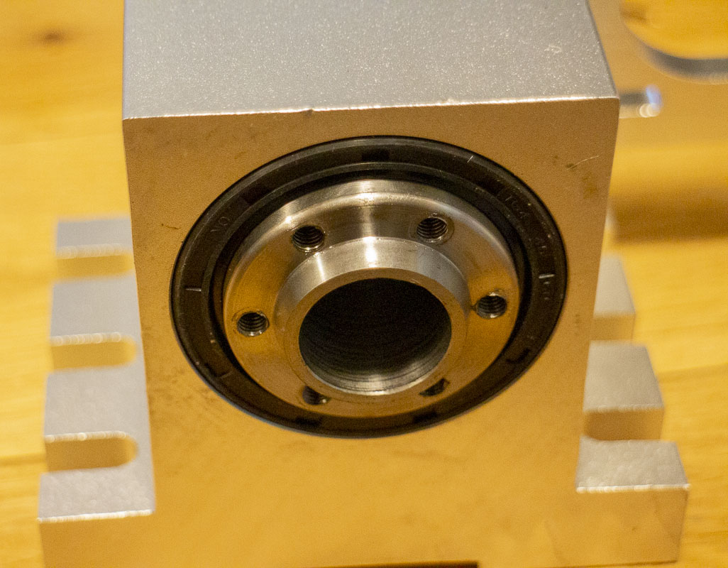
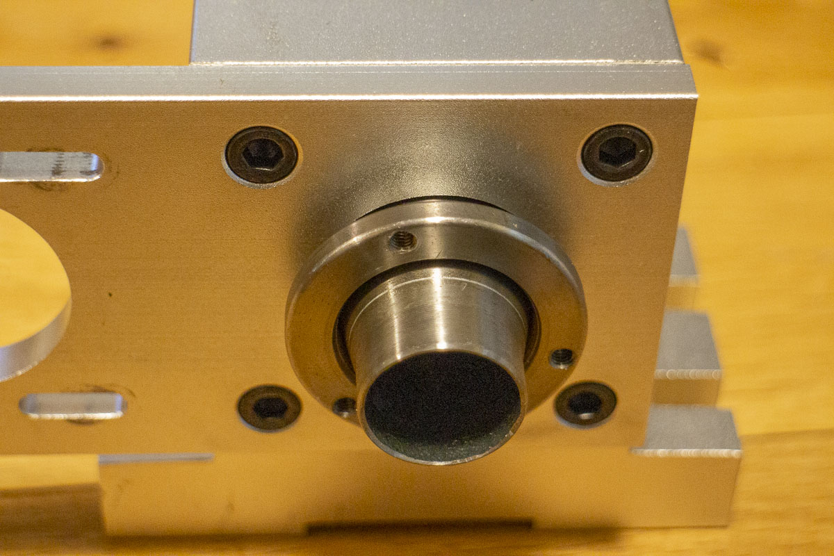
Unlike some other axii for laser, this does not have a tilt function in the base. I figure for what little work I expect to do that needed that, I’d just set up a sine bar or wedge when the time comes. This is not a challenge and I get a better tool. Most of my work will have the axis parallel to the projection plane and square to the artwork. Bolting this axis down properly aligned has proven quick and easy with my fixturing system.
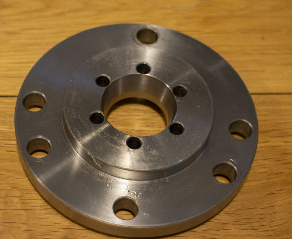
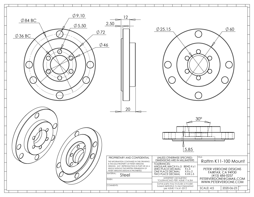
For my future reference, I made a model and drawing of the attachment plate that is on the Rattm axis. This tells me a lot for modifications that I may end up making. The plate is held on with 6x M5 screws and 3x M8 screws. The through hole of the spindle is 21.75mm. I’d like to have a collet attachment, like the HHIP ER-40 Collet Chuck (3901-5036). I have a set of ER-40 collets in stash already. Like many chucks of this size, it shares the 72mm registration diameter so it should be a simple swap out.
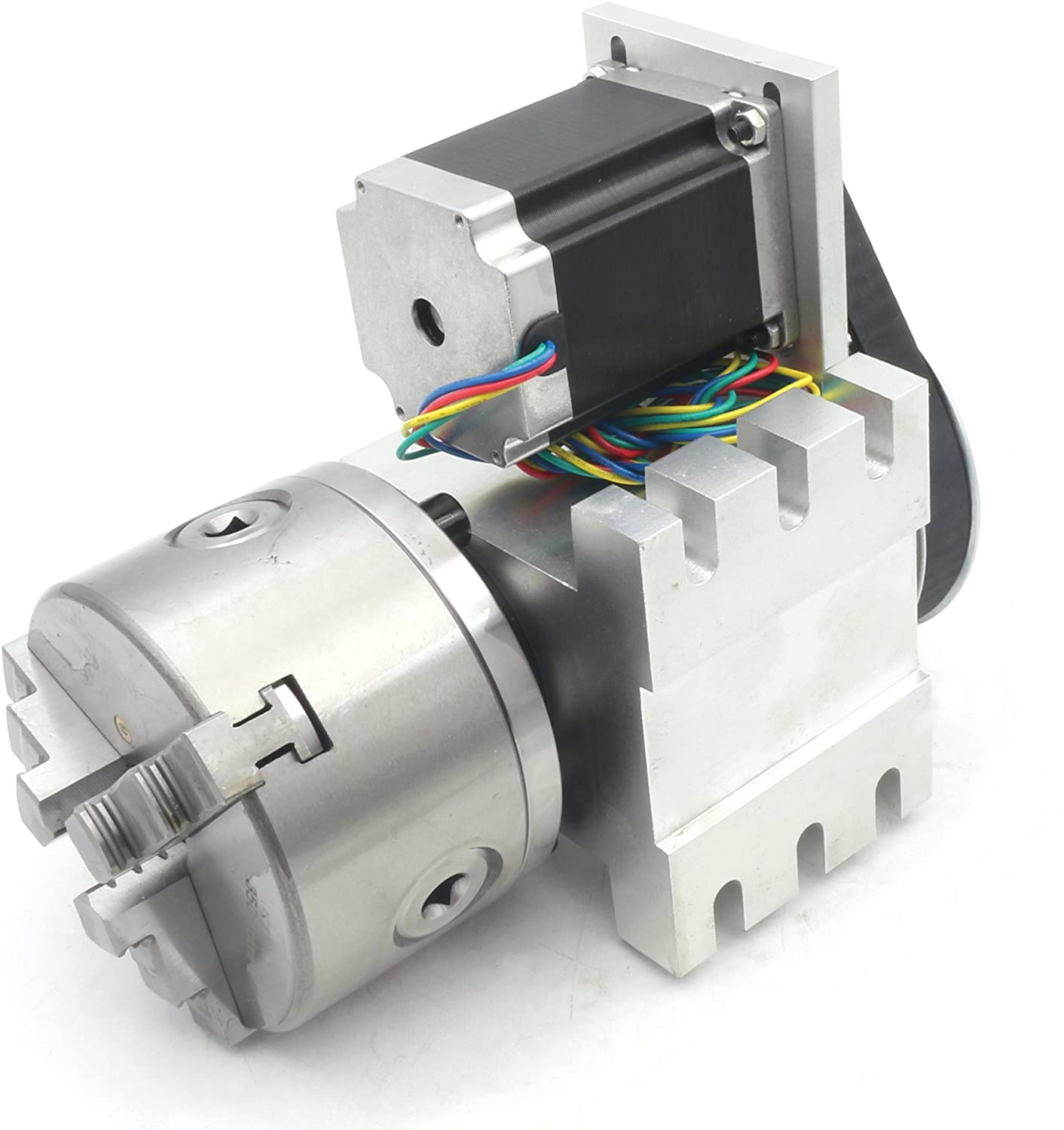
The Sanou K11-100 chuck that is mounted to the spindle looks very nice. One of the best I’ve seen in this form factor going just by appearance. It needs some work to be done on it to smooth out the function. It comes with two sets of pads and a key.
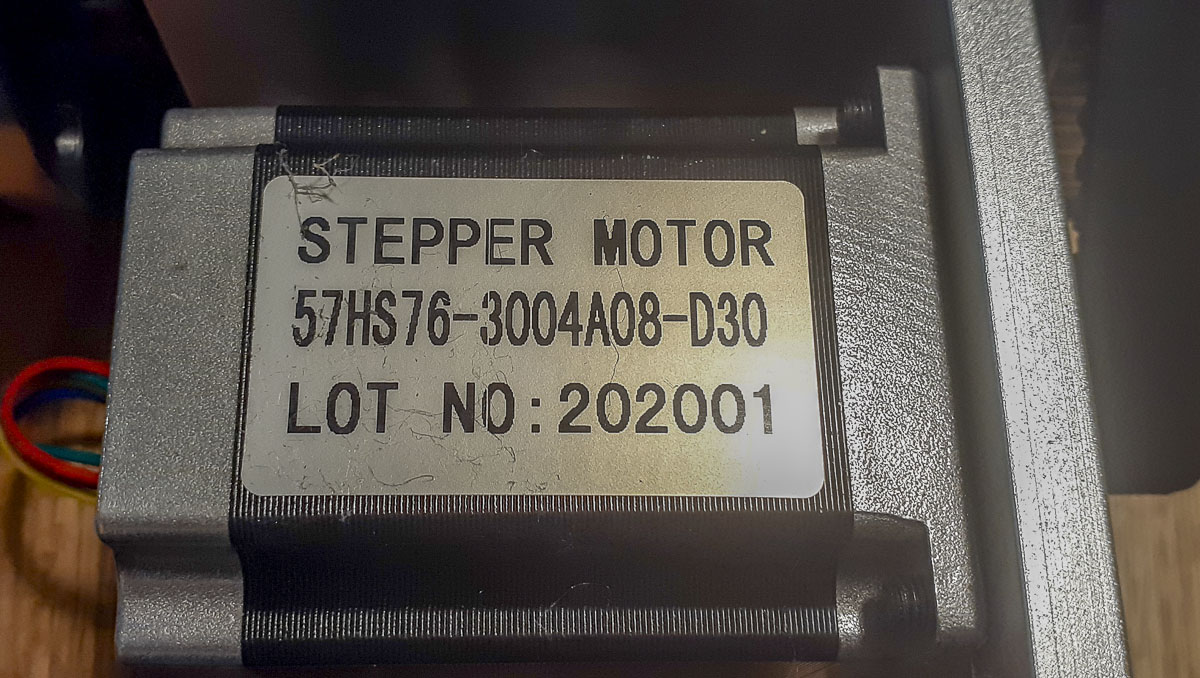
 The stepper motor for the spindle is a NEMA 23 x 76 Hybrid, 3.0A, 4.2V, 200 pulse/rotation. The ad for this tool lists the motor as a NEMA 34 86mm 4.5A but that isn’t the case, too bad.
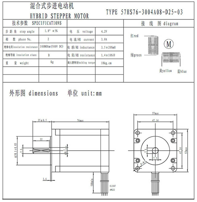
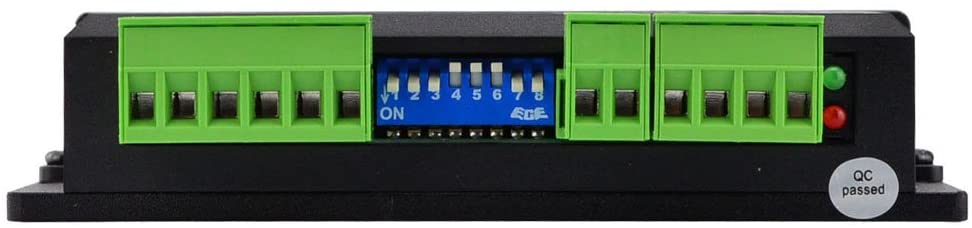
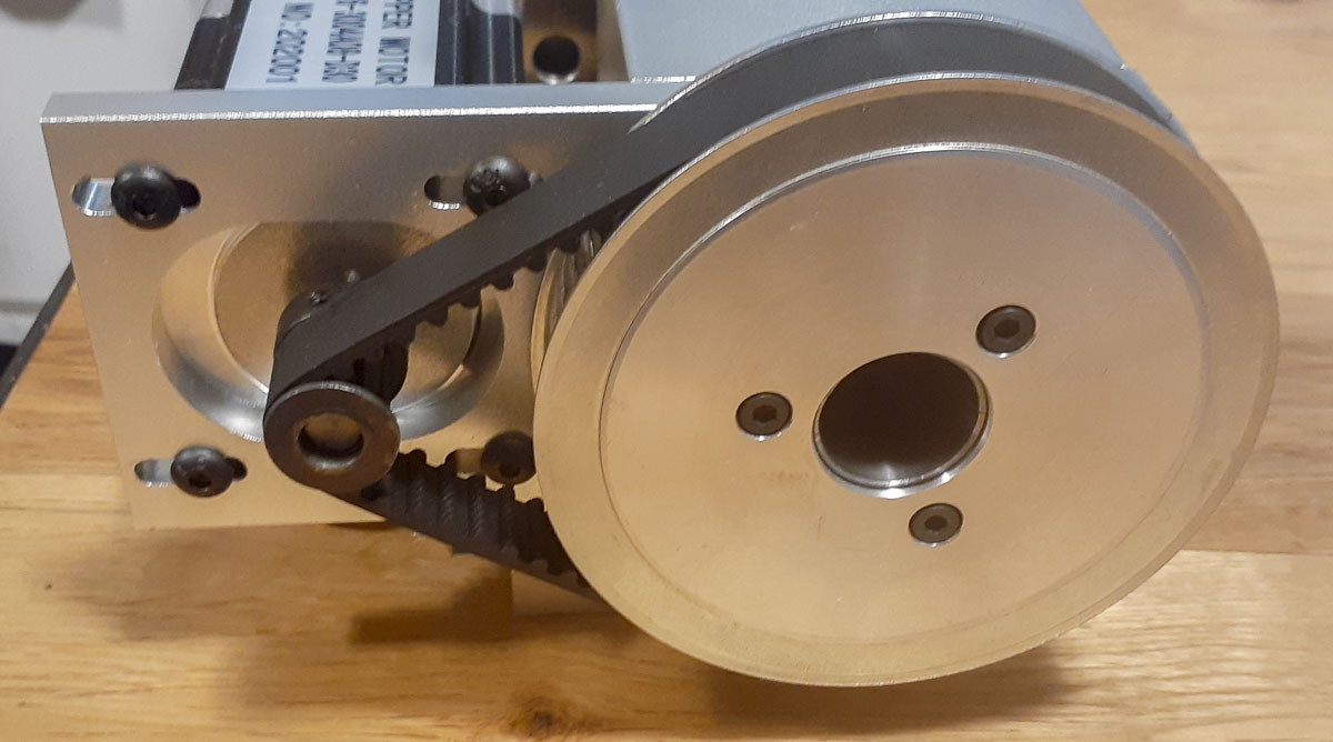
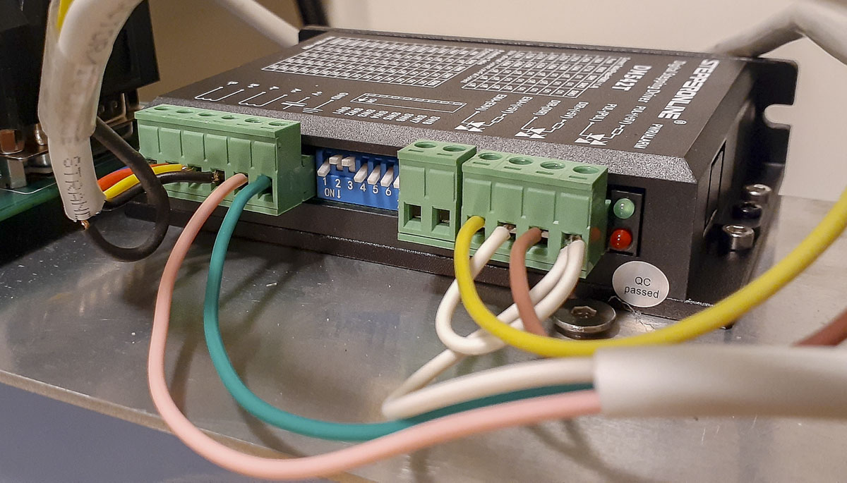
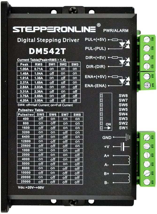
The motor has a 7.75mm shaft diameter with 90 degree 7.5mm over flat. This motor is a little odd in it’s spec but it is very similar to the StepperOnline 23HS30-2804S. The torque curve for that is described as shown: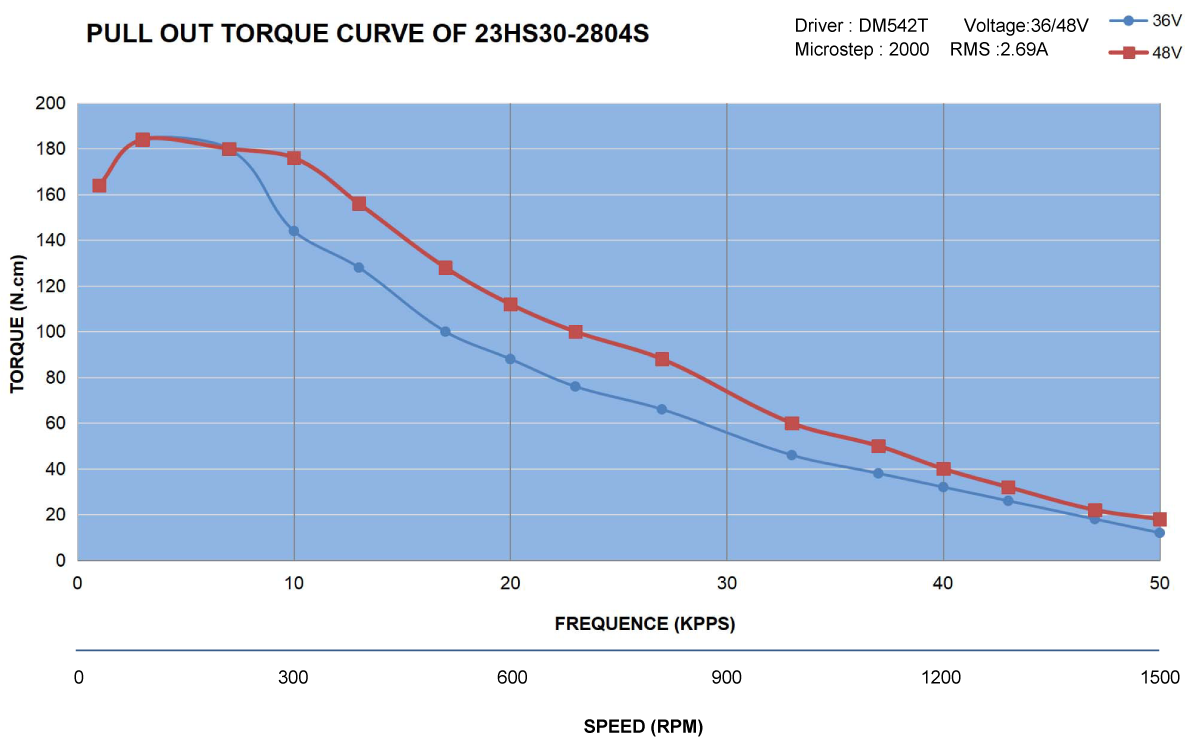 Selecting the driver was a bit more of a shot in the dark as I don’t do a lot of this type of design. There are plenty of low cost stepper drivers available that sell for $10-15. These can work if every single dollar is crucial on the front side. They can be noisy and limited in what size motors they can drive. I tend to take a longer range view. That pushed me toward the StepperOnline DM542T. It costs under $40 (delivered) and many folks seem to like them for their soft start and quiet, smooth performance. It will also run a peak current of 1.0-4.2 amps and 20-50V, giving me a wide range of motors to drive.
Obviously, the driver at 4.2 amps and a motor at 3.0 amps would be a problem if keeping a significant safety factor when running at full power for long periods. The more amps available from the driver, the more torque that can be applied by the motor while microstepping. Since there will be virtually no load on the motor when used in the laser, I expect the amperage to be well below 3,0 amps. The system is also going to have a very low duty cycle in this application. The compact size of the driver chassis becomes an important factor for fitting into the laser cabinet along with all of the other components. I wouldn’t want anything much larger in physical size than this.

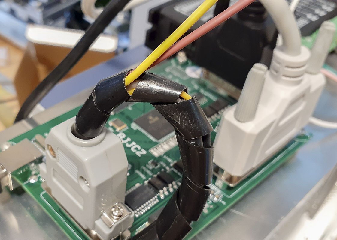
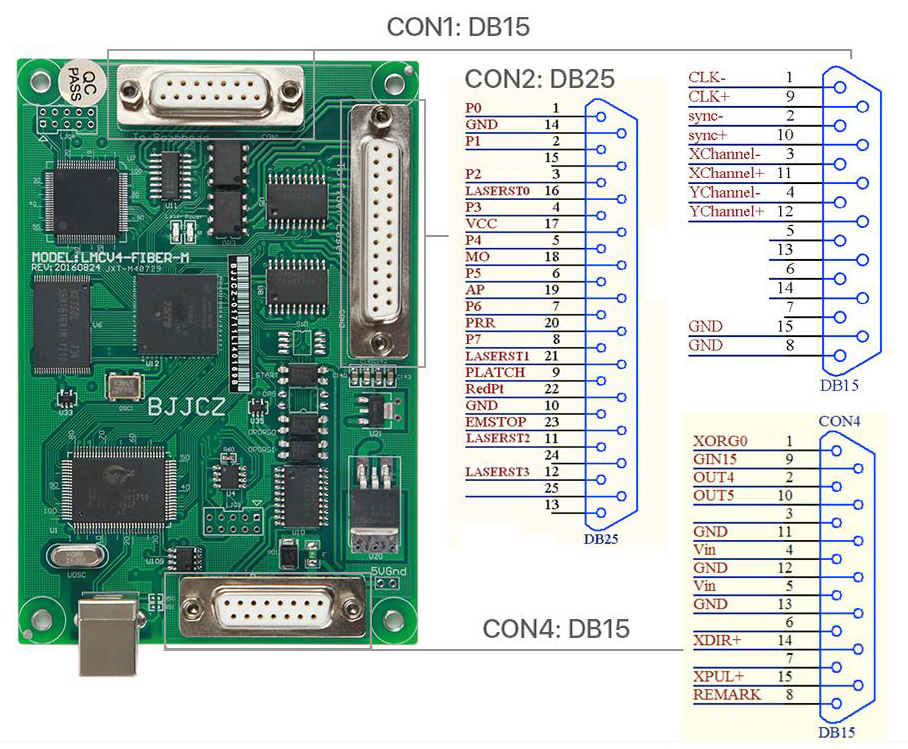
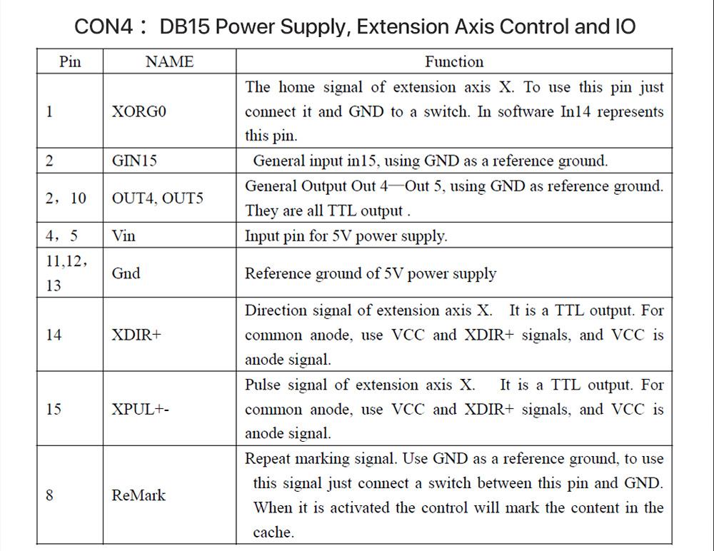
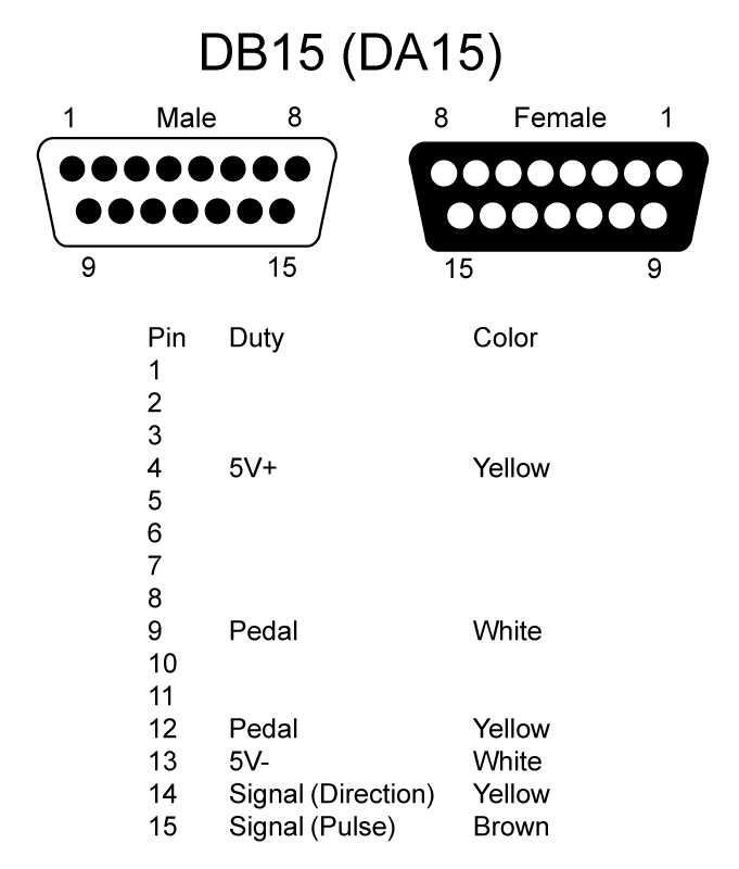
Now it’s time to look at the control and service to the driver and motor from the control board and power supplies. My laser came with a JCZ LMCV4-FIBER-M control for the galvo and laser. From this, I can also connect a trigger (foot pedal) and an axis for the rotation. That is done along with board power via CON4 (DB15) on the board. Pin 14 and 15 signal the direction and pulse for the axis (respectively). Pin 9 and 12 are for the trigger. 24v power is supplied directly from the same power supply for the laser.

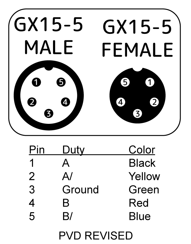
The laser unit from Vevor came pre-wired for a rotary attachment. The GX15-5 connector at the back of the box was wired as follows.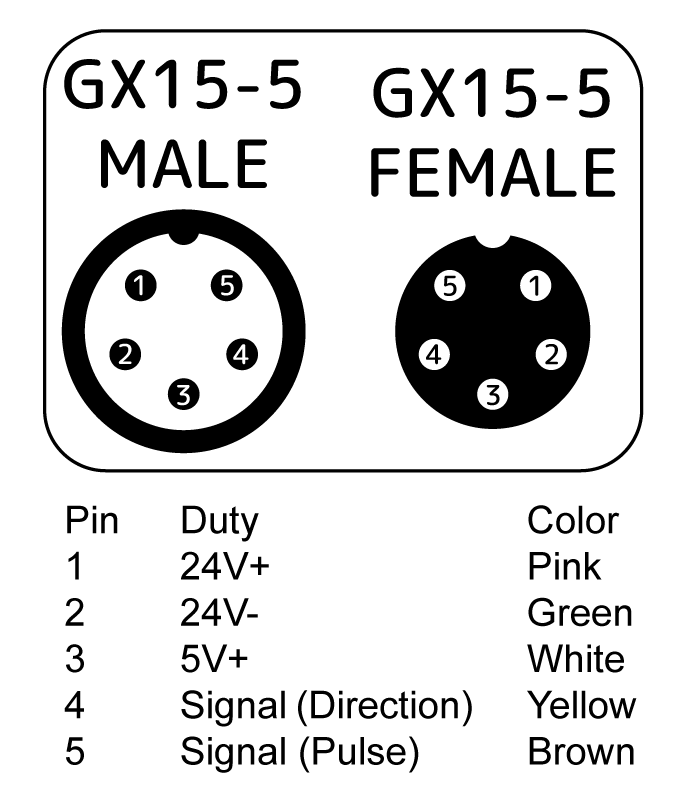
Looking at this, it is clear that this pinout is for having the stepper motor driver outside the box and a 5v line for running the driver outside of the enclosure. I don’t want this as it’s going to result in a mess in the work area and complexity in appearance. I want the motor driver inside the enclosure and convert the GX16-5 to be dedicated to running only the stepper motor. I’m going to re-wire this.
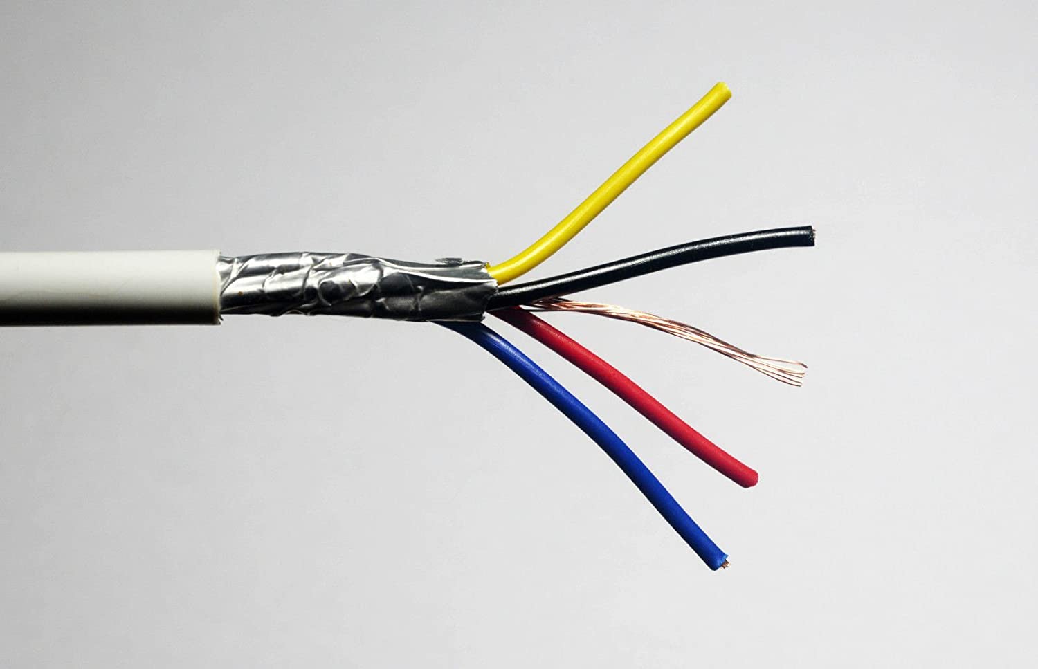
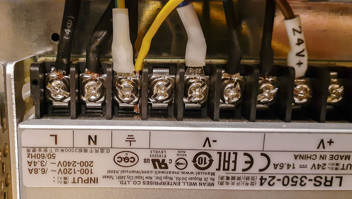
The wire I’ll be using from the driver to the GX16-5 junction and from there to the motor will be 18/4 AWG – shielded stranded wire with a ground line. I am doing this right to protect the laser and galvo control from noise created by the high frequency 24v pulses going to the motor. The colors for the cable are yellow, blue, red, black plus a bare ground wire. I’ll run that as yellow (to match system ground) outside of the bundle to the 24V supply.
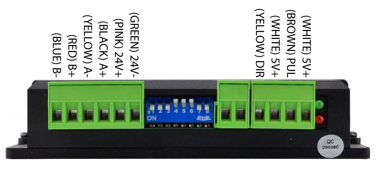
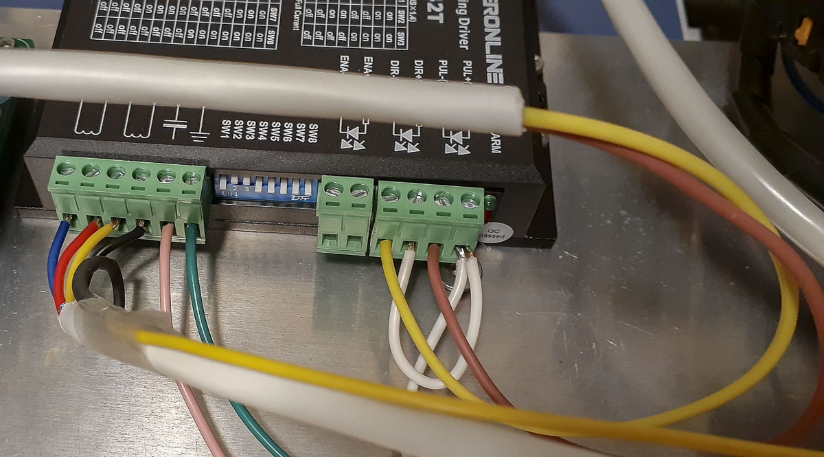
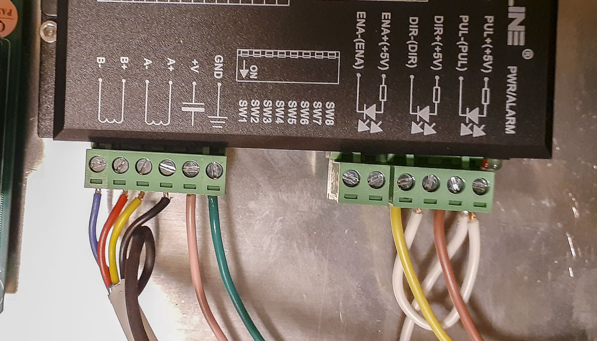
So the connector from the driver will look as follows:
Connecting the cable to the motor of the rotary attachment was straightforward:
A : Black (driver) to Yellow (Motor)
A/: Yellow (driver) to Blue (Motor)
B : Red (driver) to Red (Motor)
B/: Blue (driver) to Green (Motor)
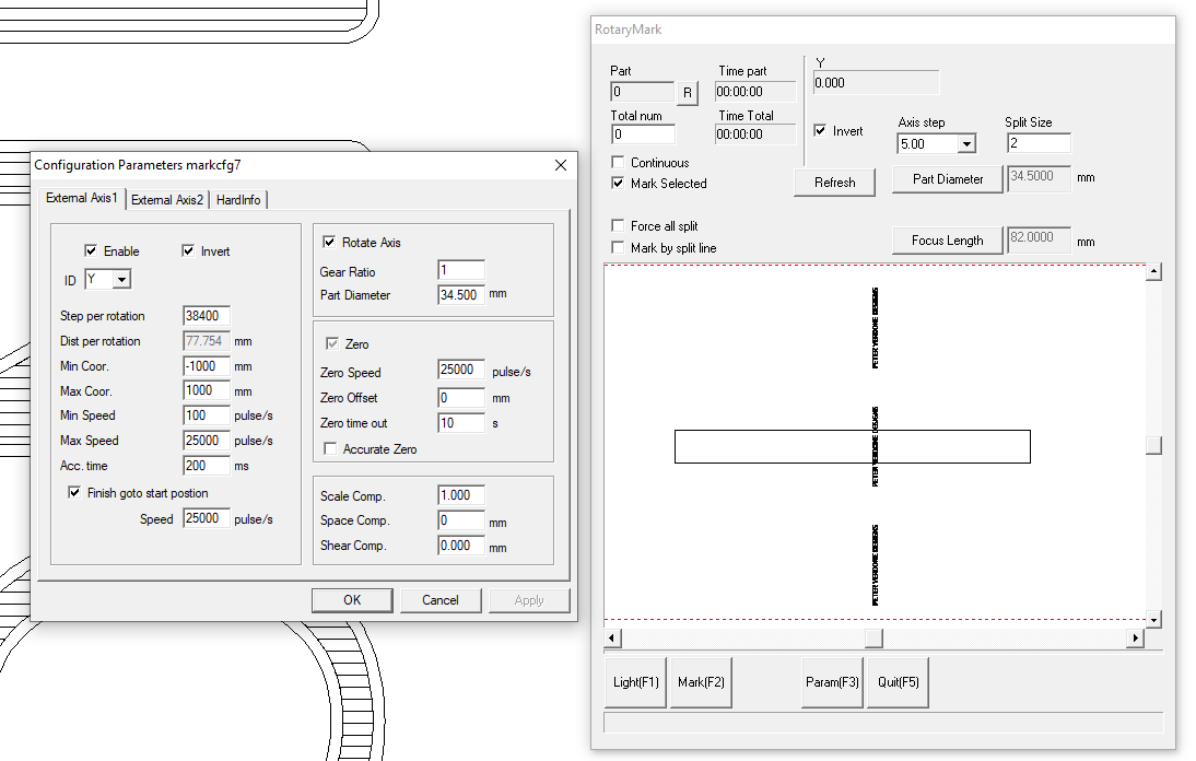
I did some coarse testing of the driver and motor through the board and decided to set the driver up to push 6400 steps per revolution. Combined with the mechanical reduction at the gearing of 1:6, that’s 38,400 steps per revolution in the software and coming out of the board. That doesn’t seem to bog the system that I noticed and doesn’t shake the table when it’s run. I need to do some more experimentation to find the real maximum speed of this motor and software. Baud, baby.
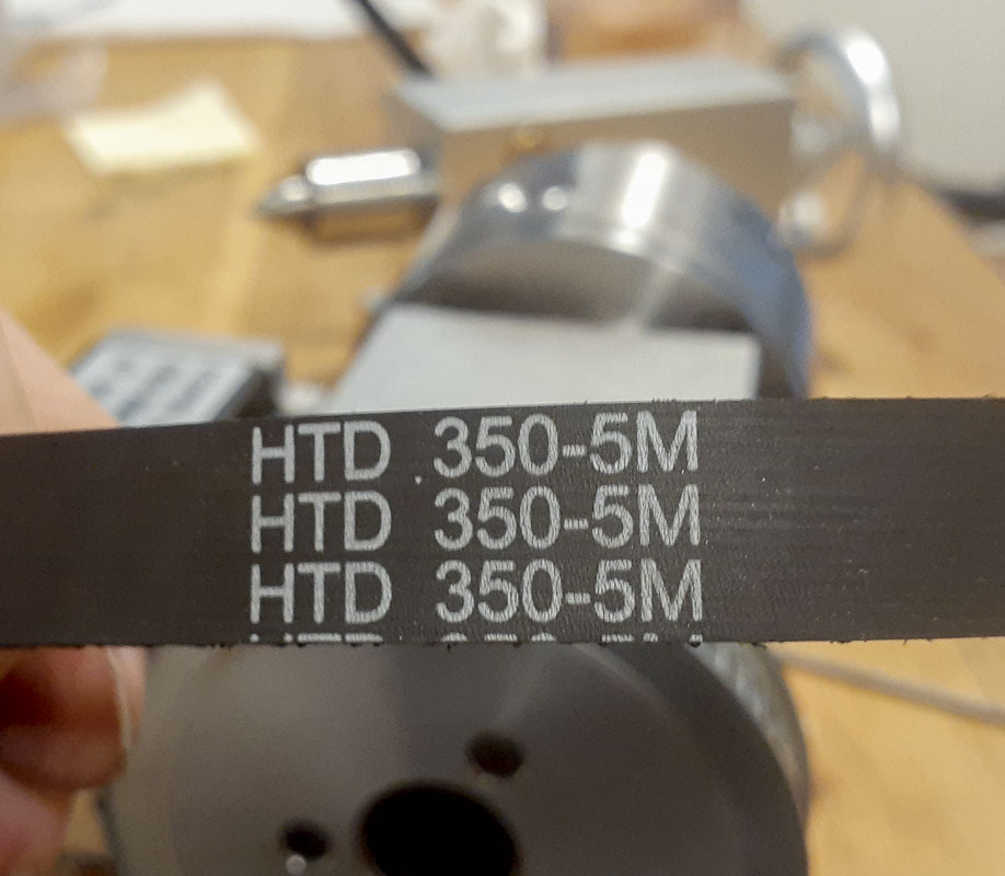
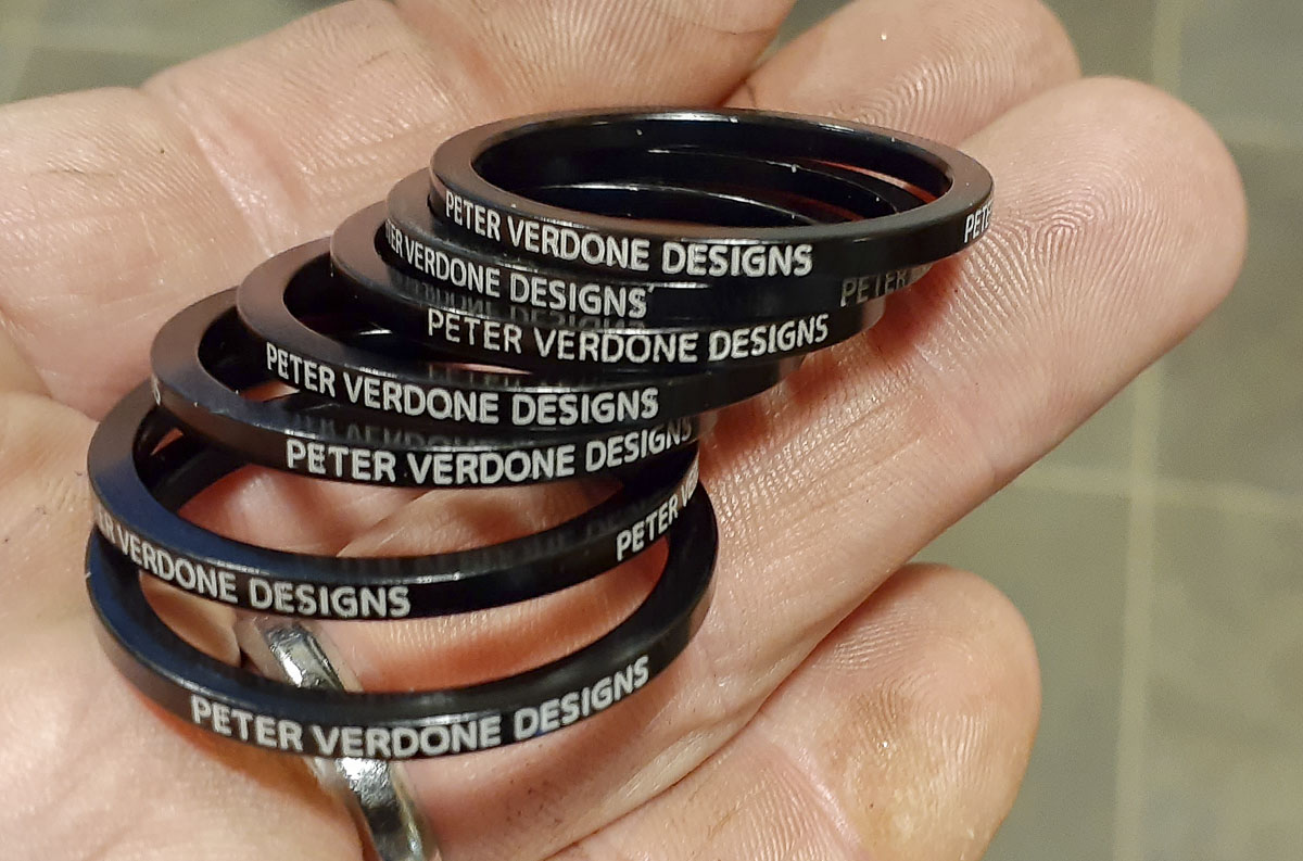
The settings that I used in the video of the 2.5mm headset spacers are as follows. I’m sure there is room for improvement but this is a start. Getting to this point is far from obvious given the poor documentation and is really the fault of JCZ and their terrible software, support, and documentation. It’s a struggle for a lot of people and for no good reason.
JefferyJ on YouTube liked what I wrote here enough to get set up with a rotary and he made a video on this process.
Here’s a great way of solving a particular marking problem. Obviously, a proper linear stage with mounted motor would be preferred but the idea is great.
I contacted JCZ on how to program EzCad to produce files to perform the output below but they were totally unwilling to give any sort of assistance with their product. WTF? This leads to significant market confusion and slows their development.
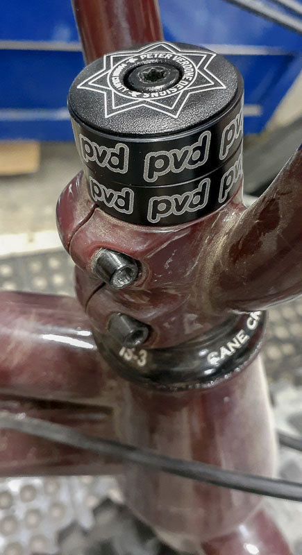
Here I am, making my mark.