More on the new frame fixture details…
I started on this path when the employer of a friend took delivery of a fiber laser for marking parts. I would have been able to get some limited access to this but, sadly, COVID-19 ate the company up and that opportunity disappeared along with my friends job. Brutal stuff.
Prior to this, there have been a couple CO2 lasers available to me. A cartesian CO2 laser (10,600 nm) and a scanning fiber laser (1064 nm) are very different and do very different work. I had figured out a way to leverage the CO2 for my data plates in the past and while the results were just ok, in the end, they would have been a lot nicer if done with a fiber laser. A fiber laser will allow me to truly mark/engrave/cut metal. A very high power fiber laser is what is used for industrial cutting. The 20w that I purchased is really not up for cutting anything but foil but it will do marking and light engraving.
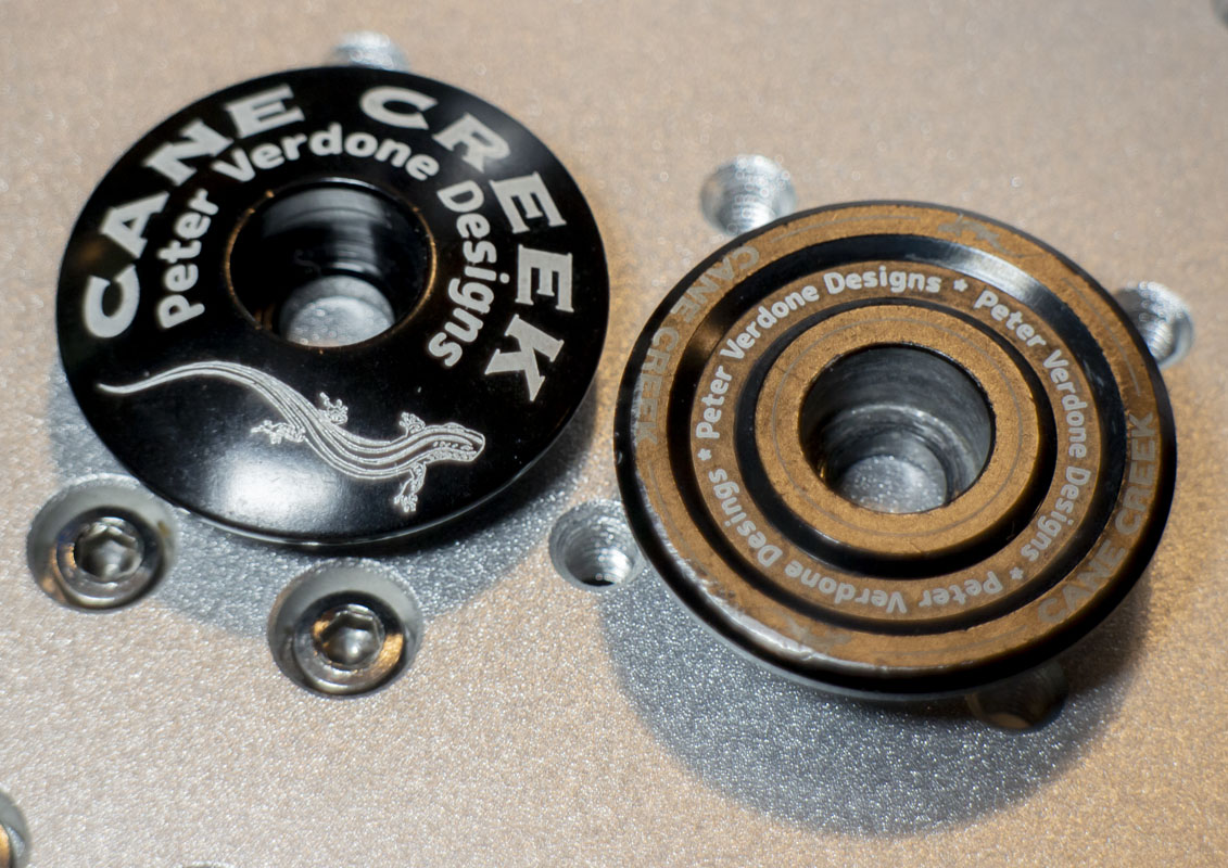
Laser marking the degree registrations for a few of the parts of my fixture that are in production seems to make a lot of sense. I could have done the engraving with a cutter post anodizing, but I didn’t think that I was going to be able to get the results that I was looking for without driving the machinist mad and also get the fine gradations that I wanted.
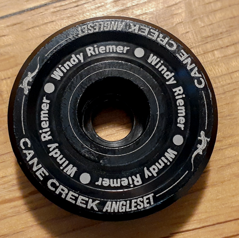
I have many uses for a laser marking system in my world. I have data plates, brake mount adapters, headset cups, and a ton of special items that I construct over time that could see graphical enhancement. I could also use it for some of the scientific devices that I make for my work at the university. Doing precice layout for hand cut parts is cool use when you aren’t paying a service for marking.
Another interesting fact, while I know a lot of folks with machine shops that produce a ton of parts that are laser etched, almost nobody that I know or even friends of friends has a fiber laser in their shop. I exist in an ecosystem that is largely built on favors and benefits that we get by knowing one another and relying on one another for help. I’ve leveraged this to get the things that I do done. Having a fiber laser in my hands could create some value for folks that I know and love.
I decided to buy one.
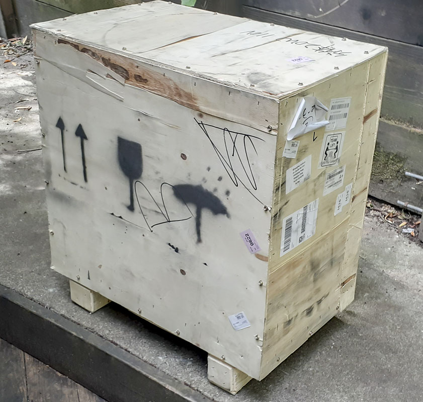
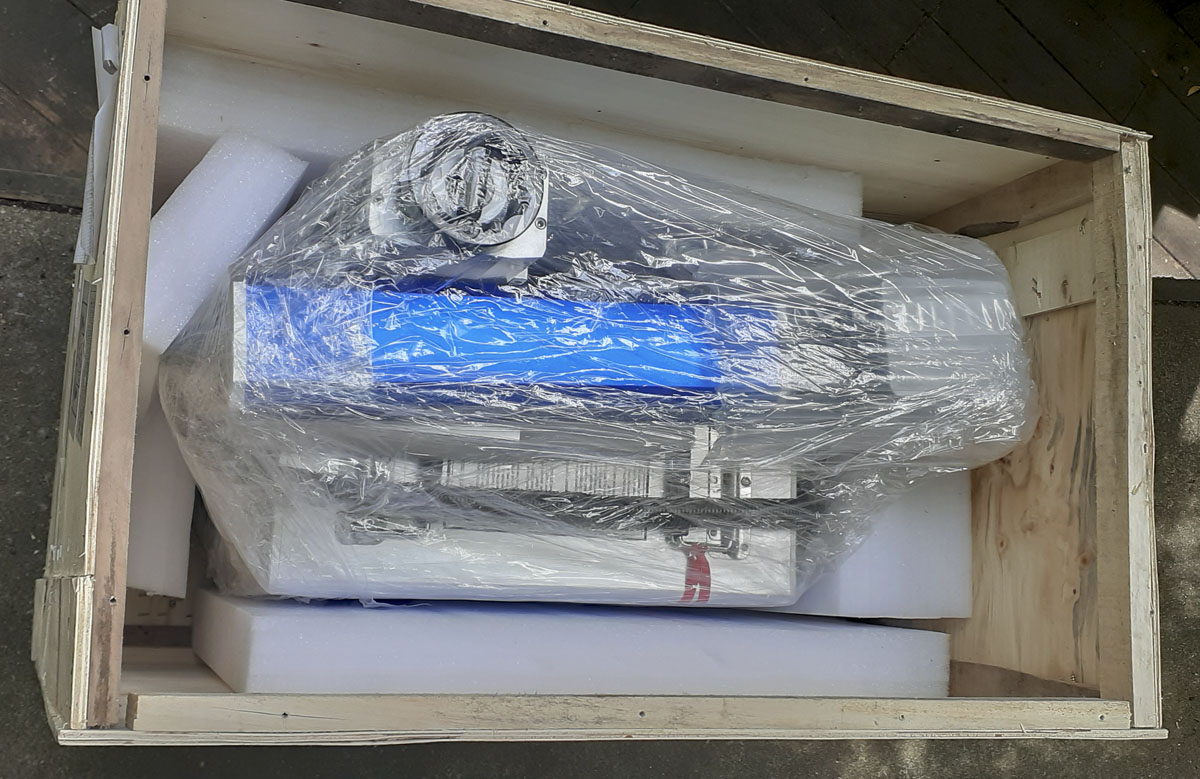
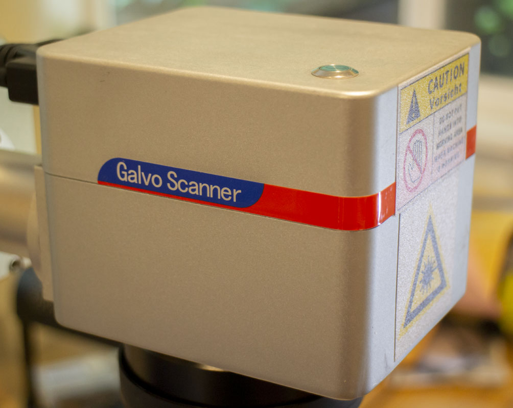
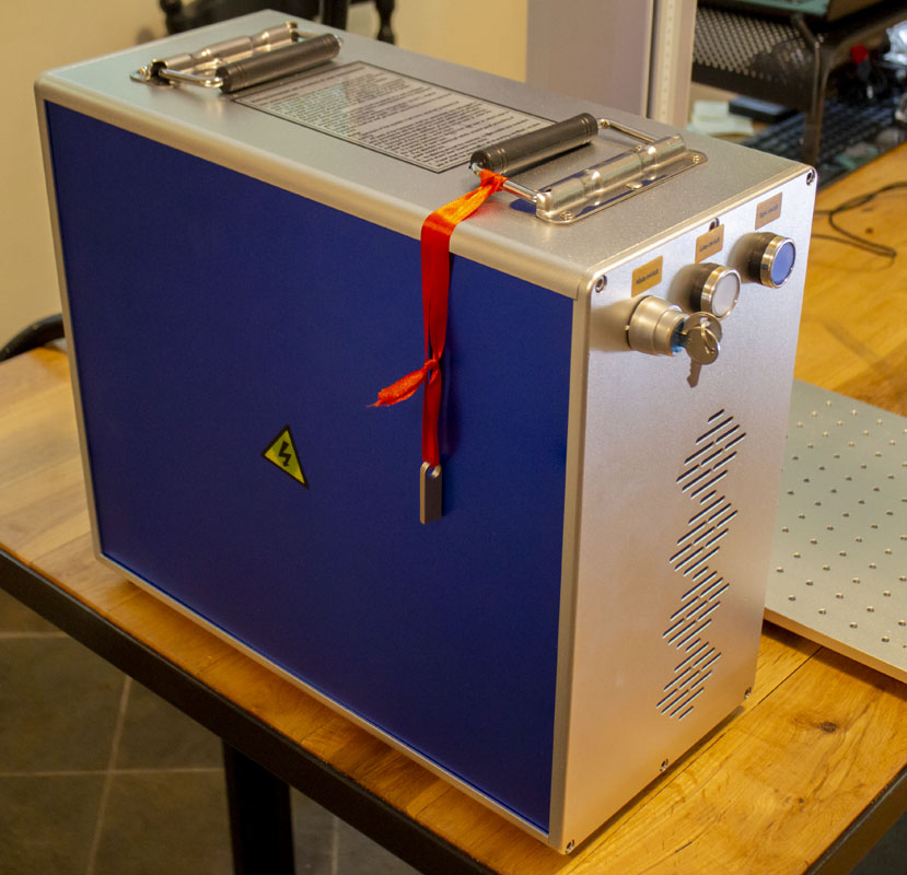
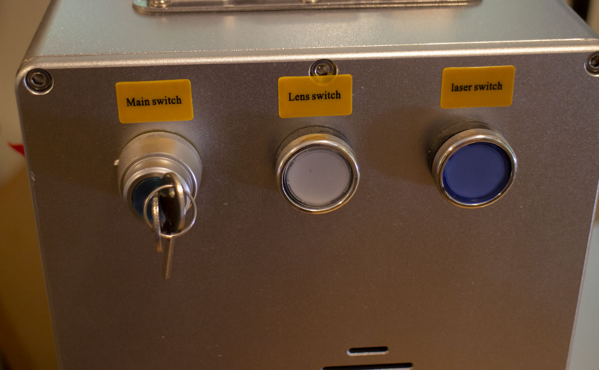
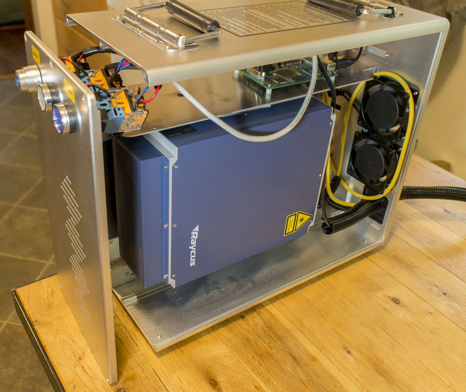
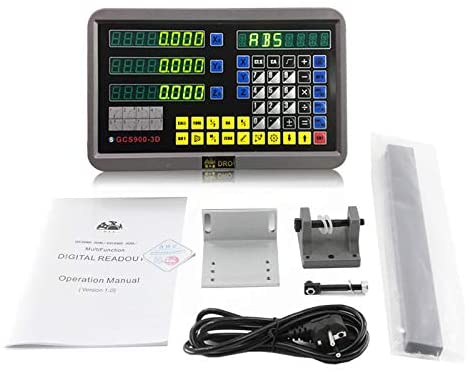
Welcome to the world of ubiquitous chineses manufacturing. Online, and with little technical specs, these things all look the same. A blue box and identical looking components.
Vevor 20W Fiber Laser Marking Machine Photoshop Novel Design 32/64 Bit Split style $2249.99
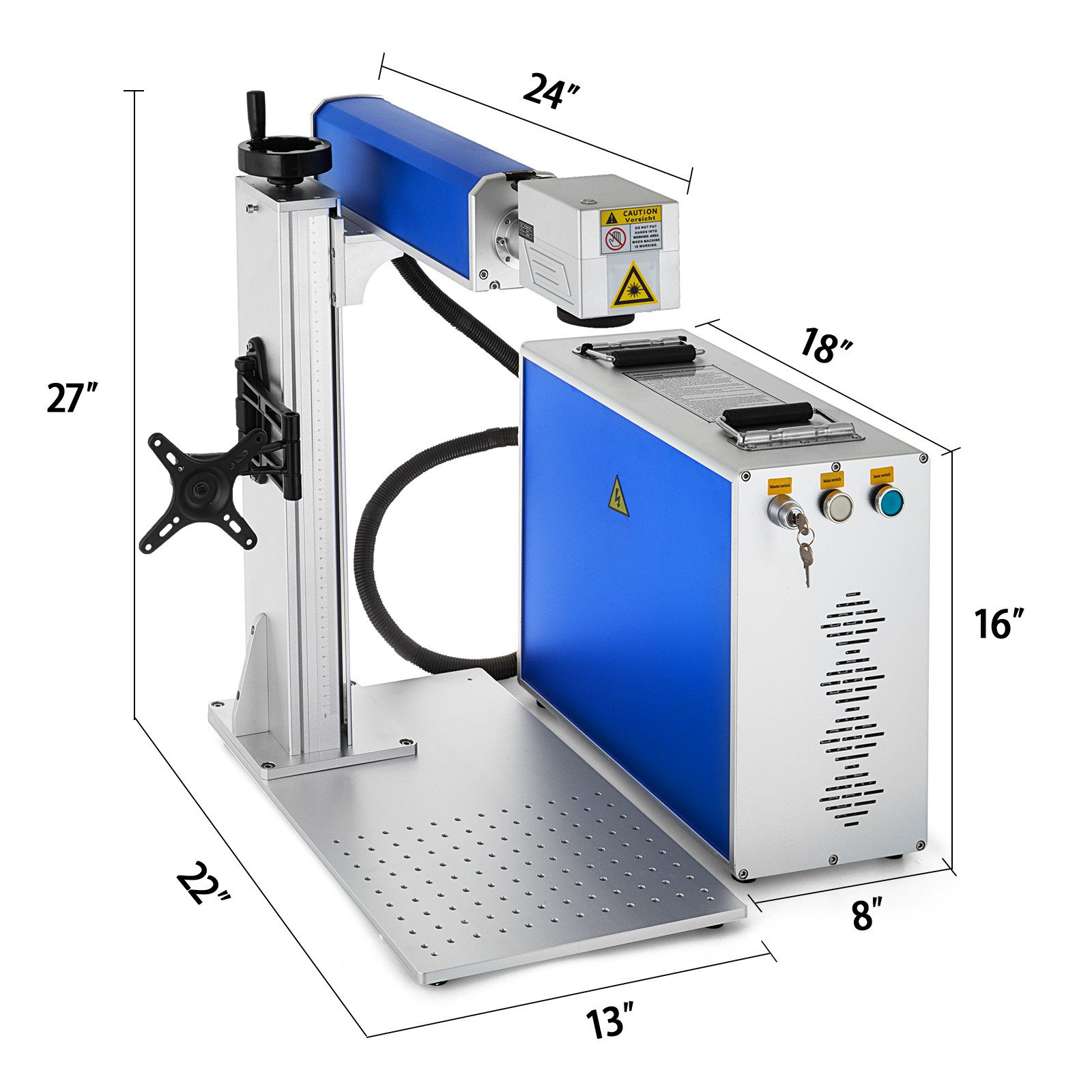
This unit is listed as WIN10/64 compatible, has dual beam laser focus, can drive a rotary attachment, and looks to be identical to other units advertised for a lot more money. Of course, the devil is in the details. It’s what’s inside that matters. What is the laser? What model galvanometer is it? Where were corners cut?
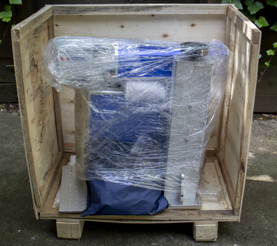
It’s not easy finding this out prior to purchase. There are few resources where folks compare their machine internals. As I usually do, I decided to document these details upon delivery.
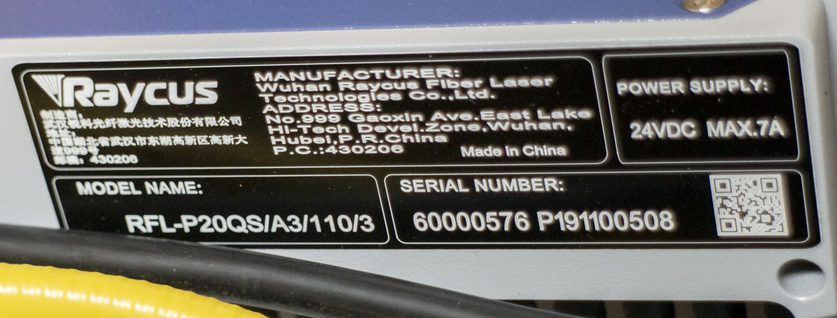
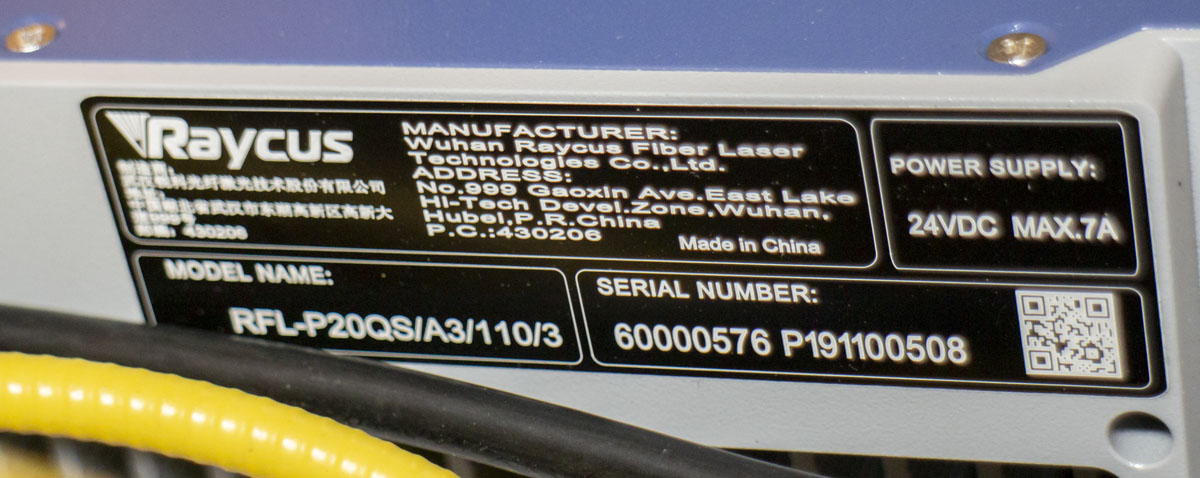
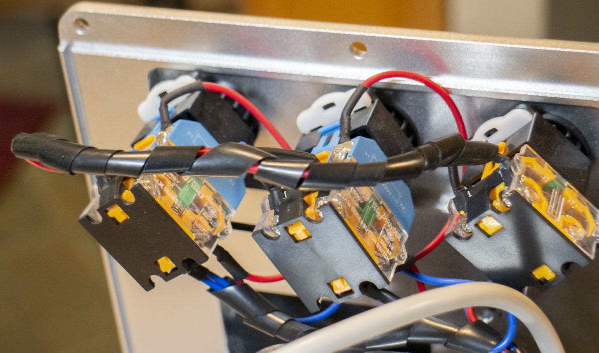
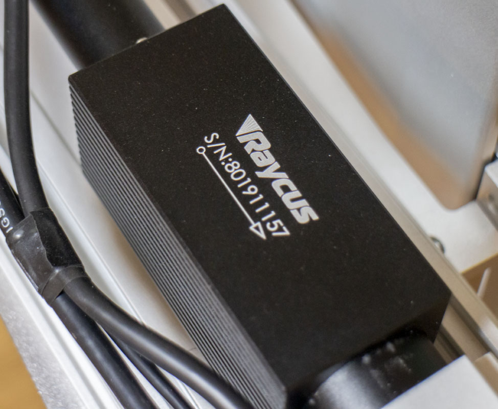
- Laser: Raycus RFL-P20QS/A3/110/3, 30-60 kHz, Q-switched, Ytterbium Pulsed Fiber Laser. A very cheap and low end laser but fine for my needs currently.
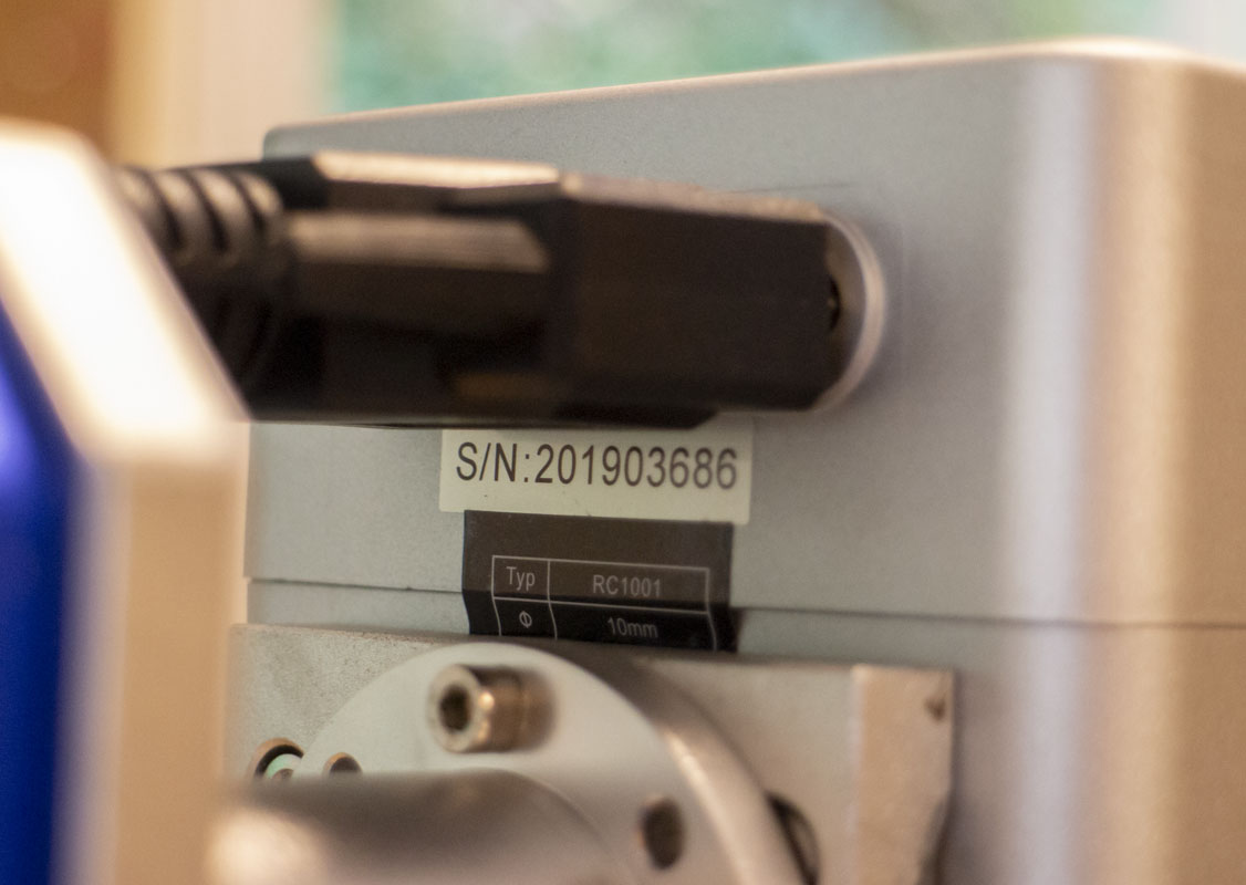
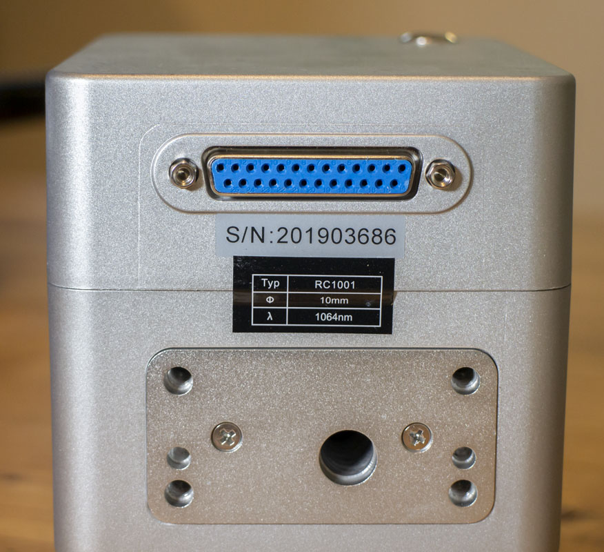
- Galvo: Cloudray RC1001 1064cm, 10mm
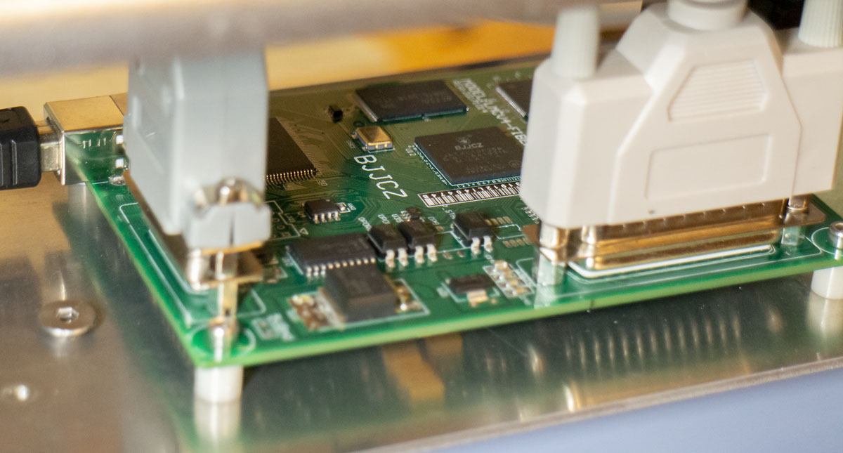
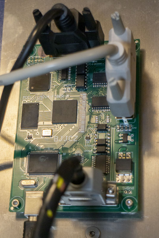
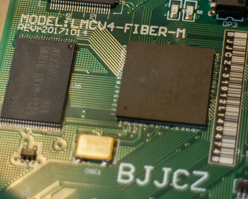
- Galvo Board: LMCV4-FIBER-M (BJJCZ), Version 4.0.2, REV: 20171014, BJJCZ-31912LI40474B
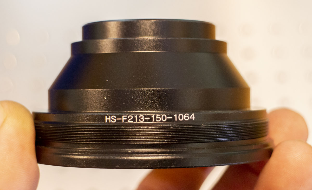
- Lens: HS-F213-150-1064. This was described as a 110×110 area scan in the ad but turned out to be 150×150. Not an upgrade for my needs.
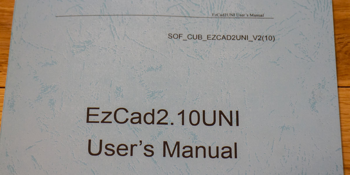
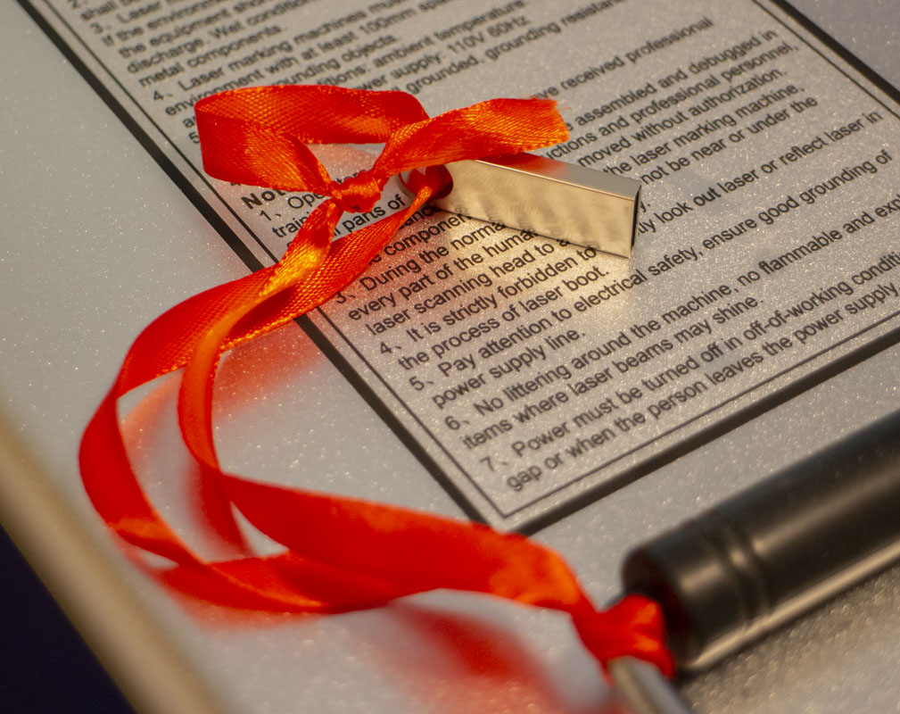
- Software: EZCad 2.14.9 on USB thumb drive w/ paper and .pdf manual (V2.14.11 available.)
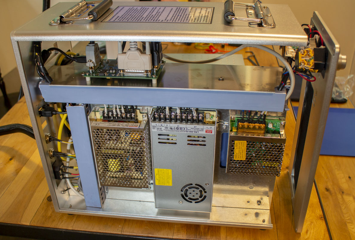
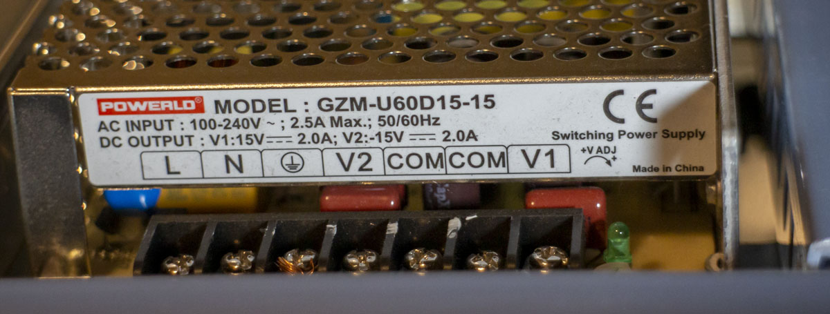
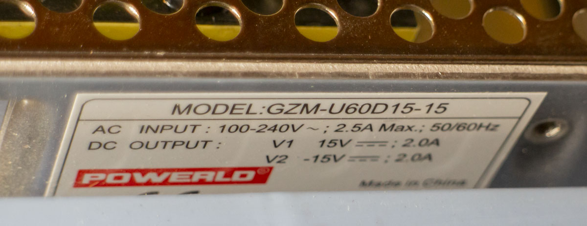
- Switching 15V Power Supply (Galvo): POWERLD GZM-U60D15-15
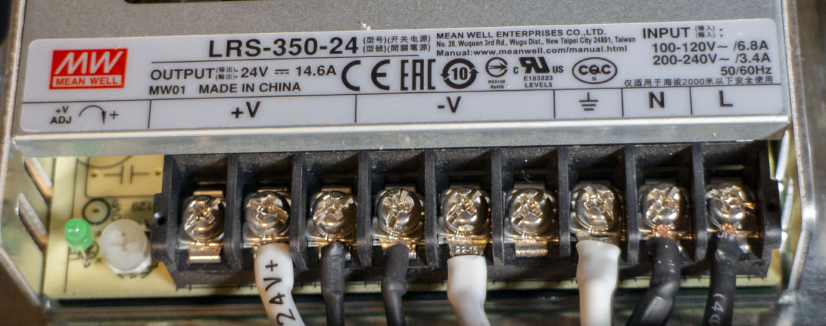
- 24V Power Supply (laser): MEAN WELL LRS-350-24
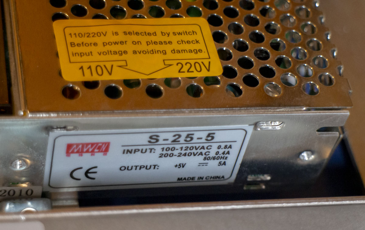
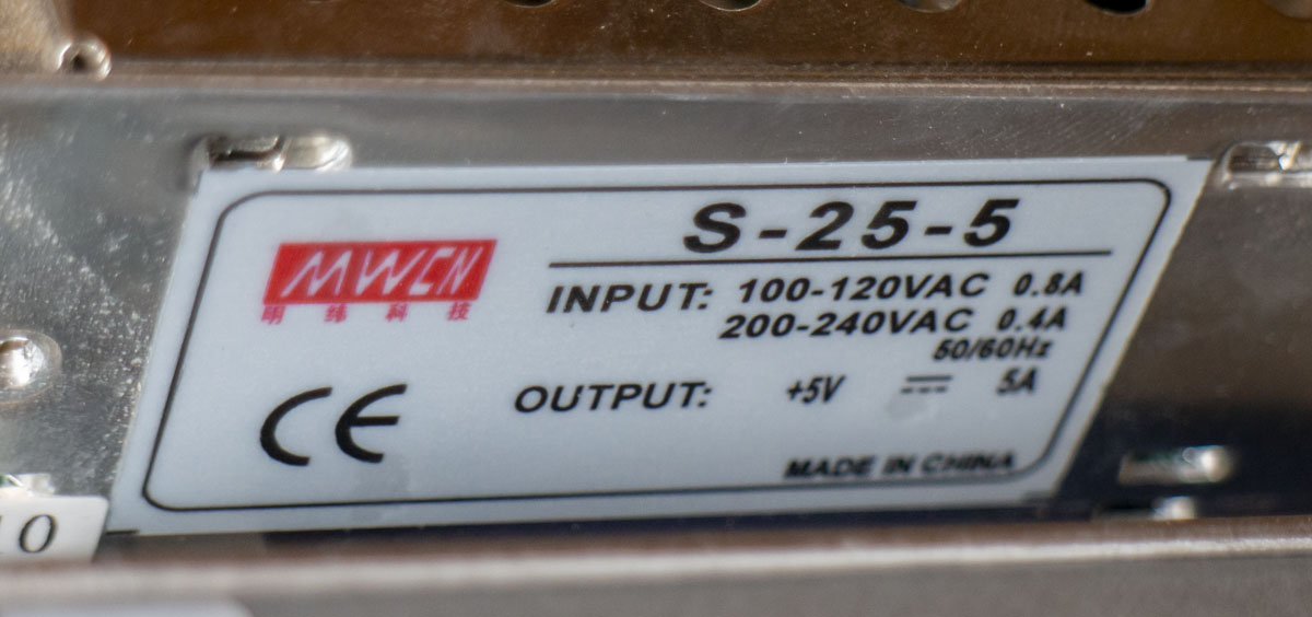
- 5V Power Supply (LED & Galvo board): MEAN WELL S-25-5
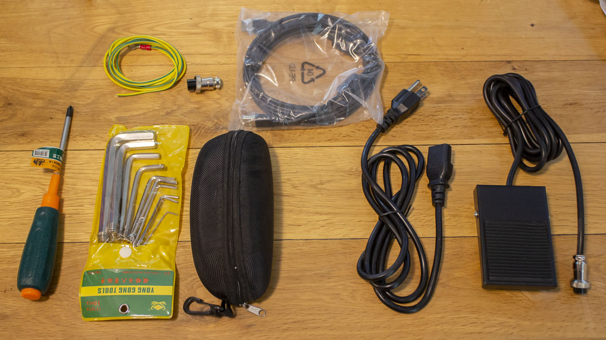
- Foot Pedal: Tend TFS-1, 10A, 250VAC
- Branding: Shandong Kehui Laser Equipment Co., Ltd
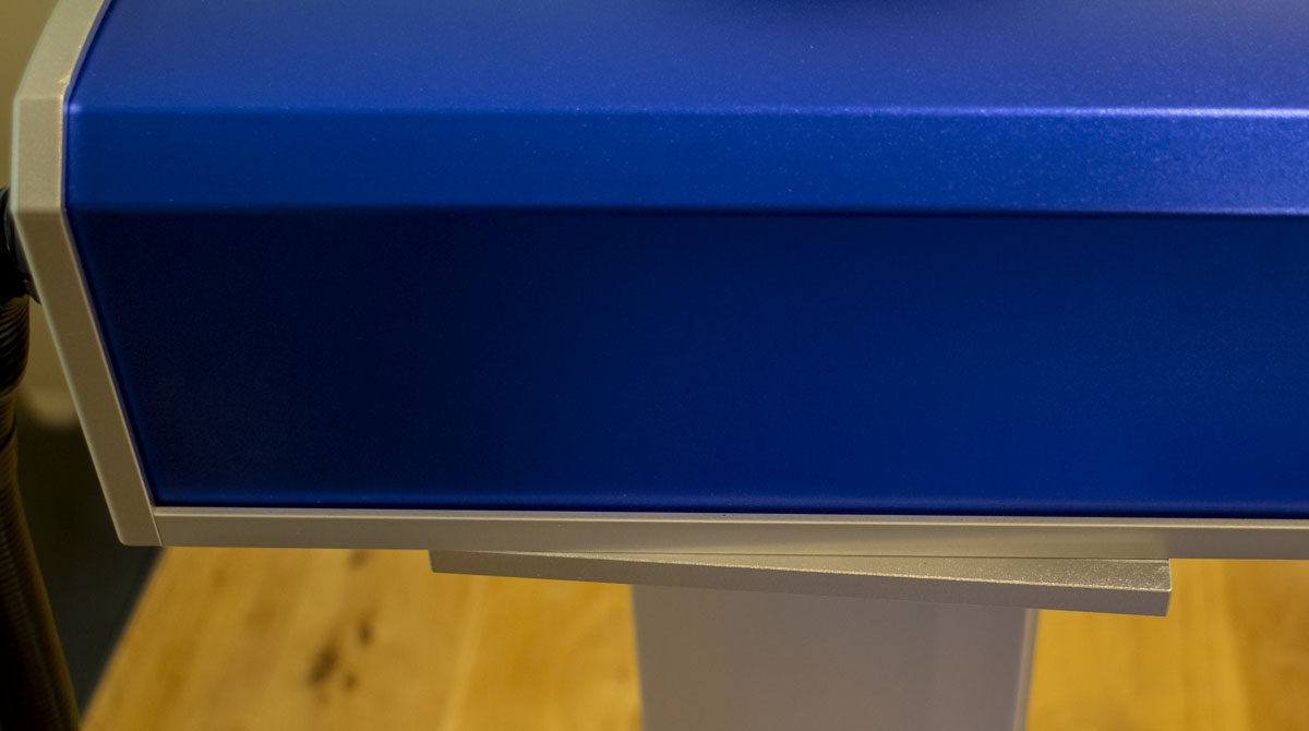
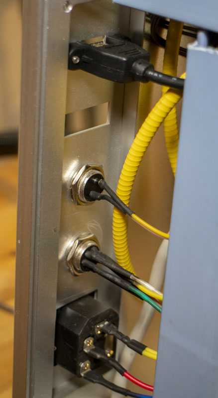
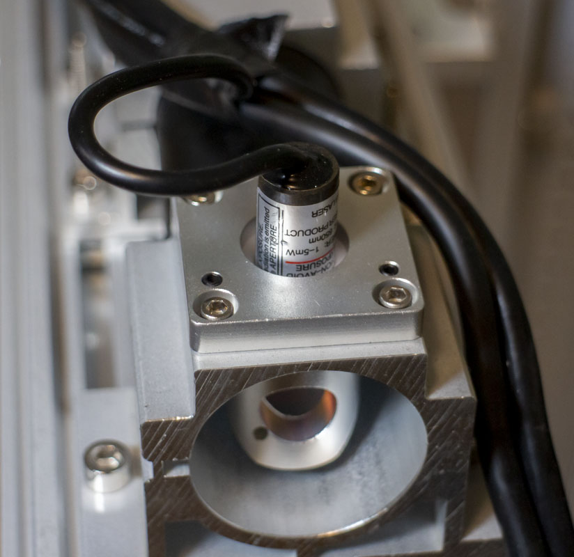
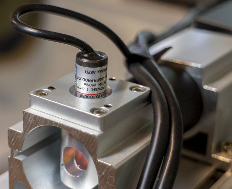
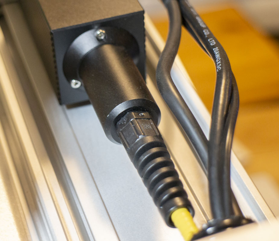
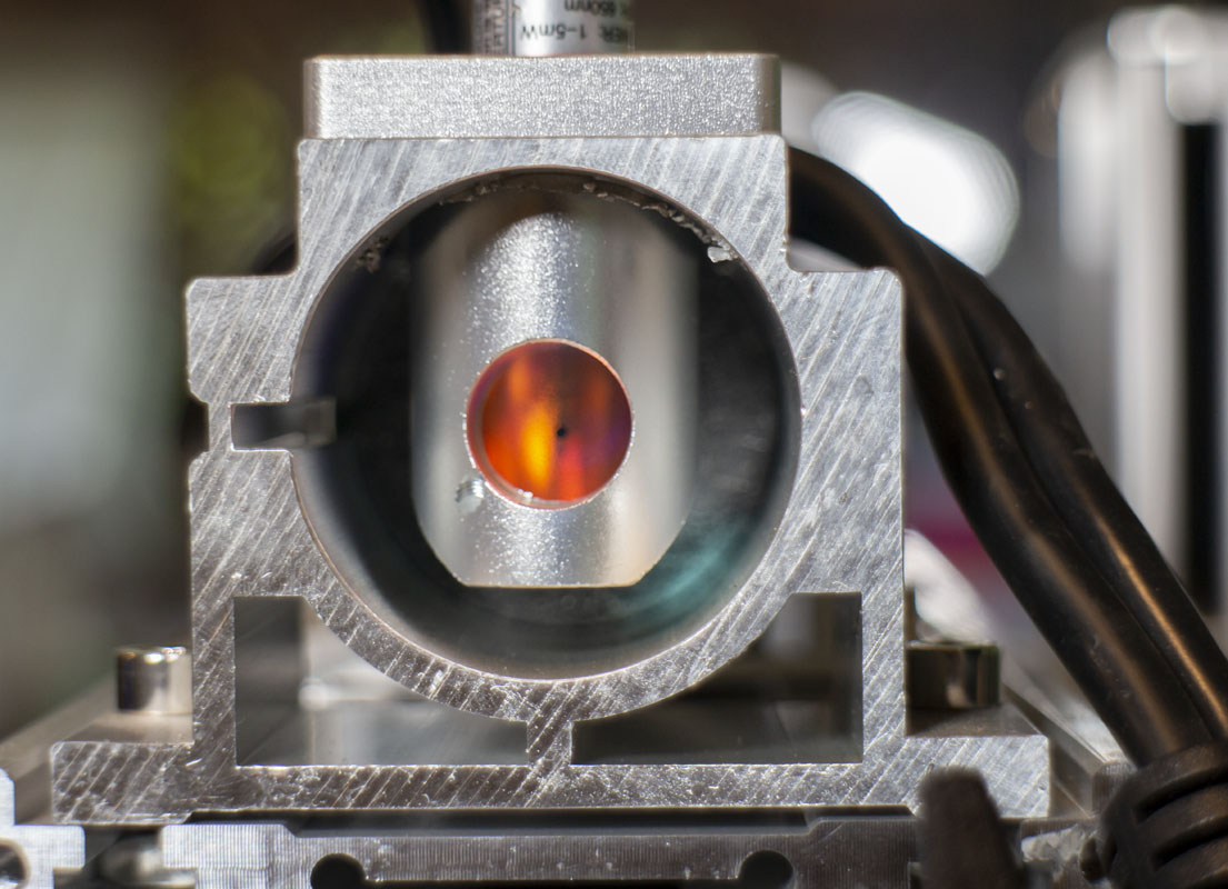
A tool like this isn’t just about the laser or electron flow, it’s also important that there is precision alignment and that remains true when the tool is adjusted. I would need to inspect every part to a reasonable degree to ensure that the projection plane was orthogonal to the part plane and that it remains on axis as the distance is changed.
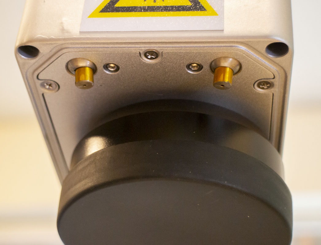
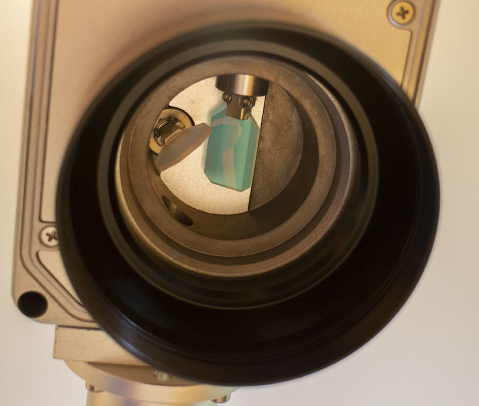
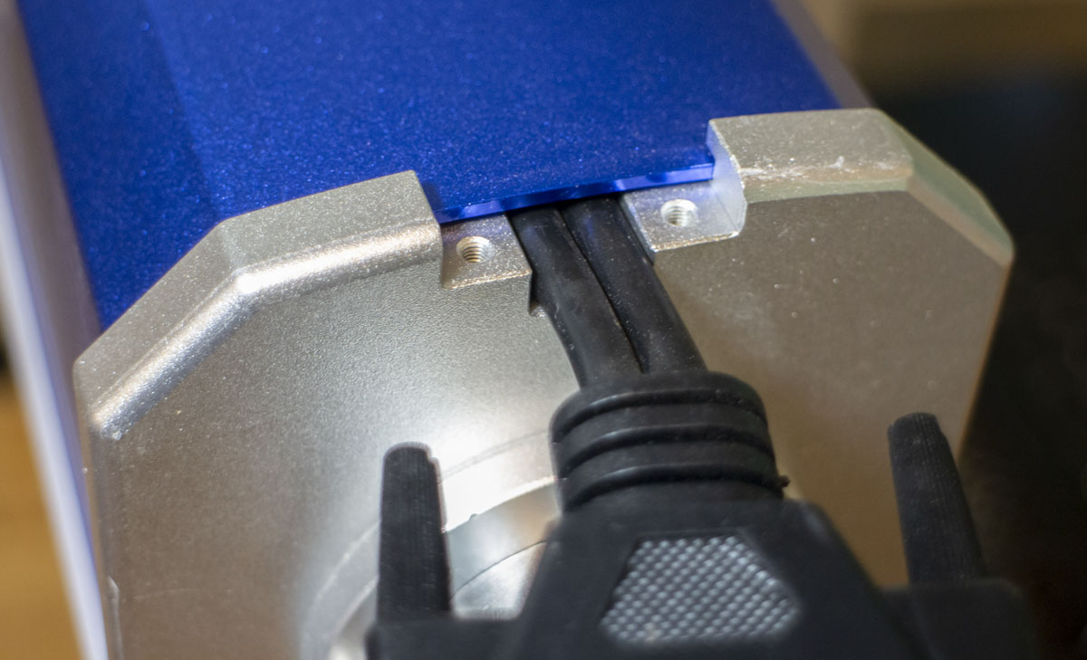
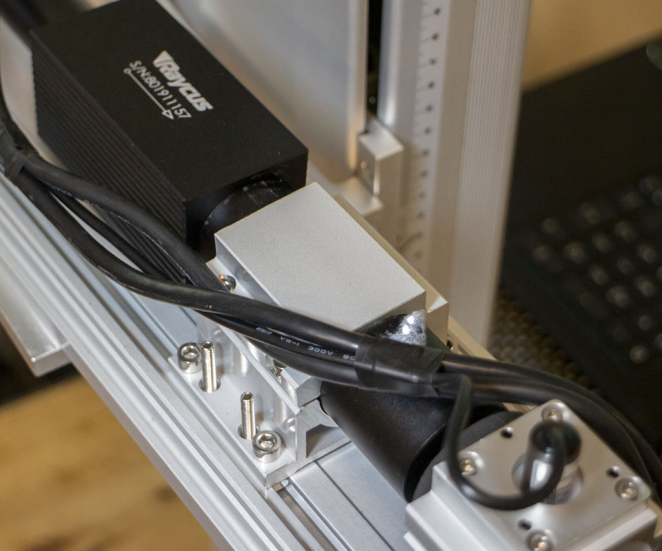
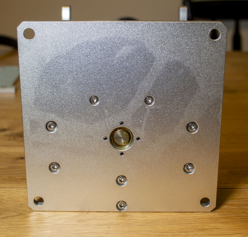
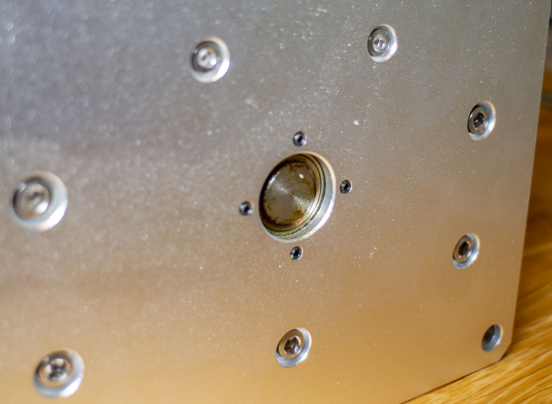
The laser emitter is aligned to the galvo axis with four set screws. The distancing can adjusted by sliding along the extrusion plate. While it may work, this whole arrangement for the laser and galvo is not very good and could see real improvement from an optics lab perspective. Not something that I’ll be working on now but I may if I get very serious about laser marking and engraving.
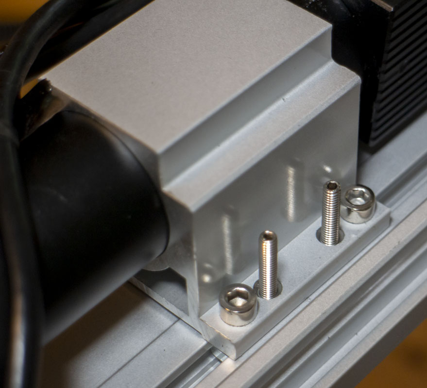
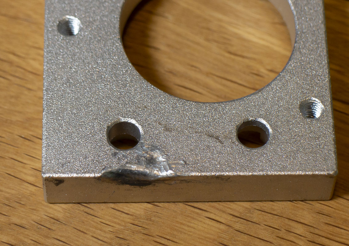
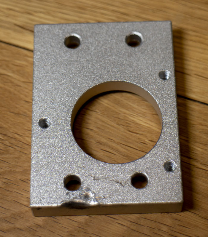
The bottom plate is the means that all optical alignment is done with four screws almost in plane. This is flimsy and would require a very high level of precision in construction to work very well, and this is very cheap construction.
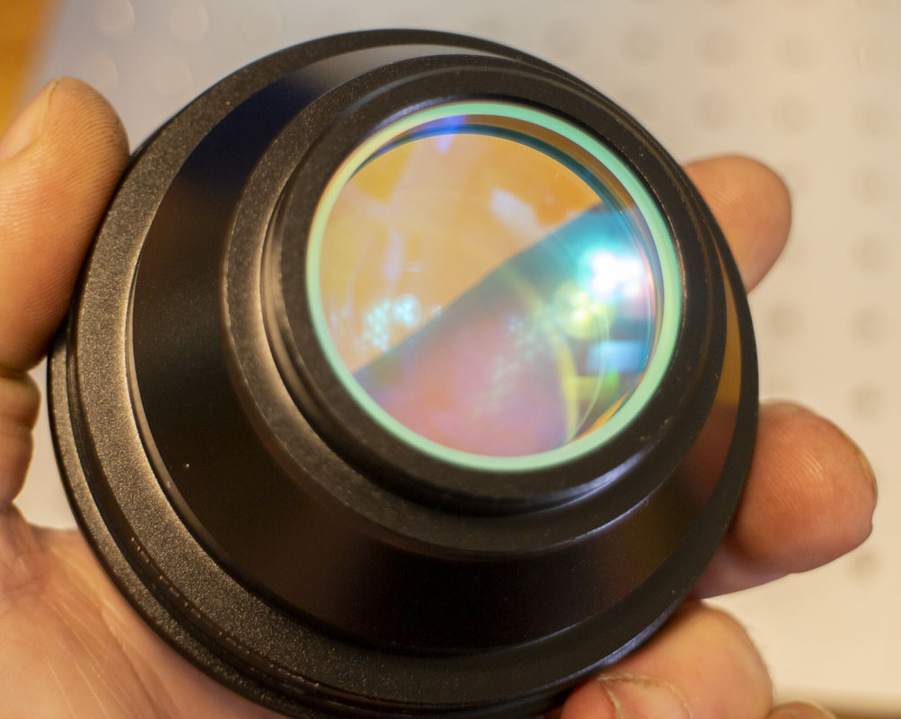
1064nm F-theta (Fθ) scan lenses get important when looking to do high quality work. From what I’ve been able to gather, the shortest focal length for a particular job is prefered as long as you aren’t bouncing right up to the very edge of the system. This gives the galvo some room to work for fine registration detail, reduces the beam diameter, and improves laser power. If a galvo has a range of 15 degrees and you are only using 3 degrees, you are missing an opportunity to have 5 times more mechanical precision at the focal plane. Working against that is that distortion is typically increasing as we move from the axis. Several software corrections are made for galvanometer and lens distortion to help fight this. It’s a balancing act that requires testing to ensure that the results are what is needed. This is a big deal and is worth keeping an eye on.
This unit comes with a F213/150×150 (HS-F213-150-1064) lens. I also got
- F290/200×200 for the most critical job I have on hand.
- F63/50×50 for some very small detail work.
- F130/90×90 for my data plates
- F420/300×300 just in case
Having these five lenses on hand will give me a lot of control over the output. Seeing that cheap F-theta lenses can be had on ebay delivered for about $60, it is worth playing with for anyone.
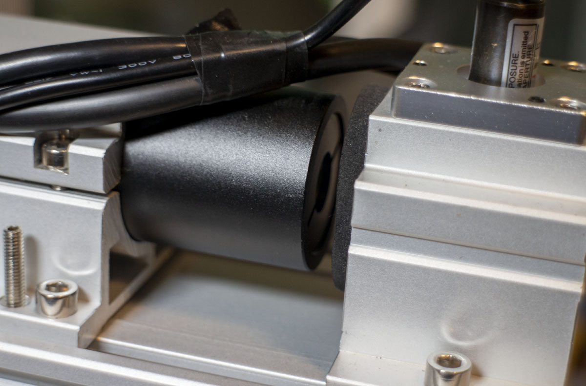
Most of the cheap fiber lenses have M85x1 threading. This galvo unit has a M68 thread while others are M79 threaded. The lens and galvo are connected via an adapter ring. This unit has a 30mm height ring. Were this an M79 threaded galvo, a 34mm ring (M79-M85 H34) and a 18mm ring (M79-M85 H18) is also available. I’m still looking for M68 options if anyone knows of them. There are other rings if you look around. Gotta be careful not to destroy the geometry of the system but mainly, don’t bump the galvo mirrors.
I still need to explore the real costs of using a cheap lens versus a more expensive lens. Is the distortion far greater? Does it reduce the beams efficiency greatly. Does the axis of the threads precisely match the lens axis? It would be possible to produce terrible results when focusing in too closely on a single parameter (focal length) and not the whole picture (quality results).
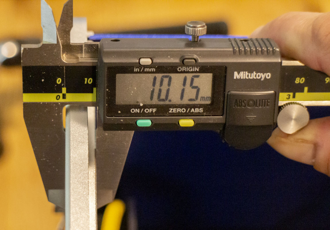
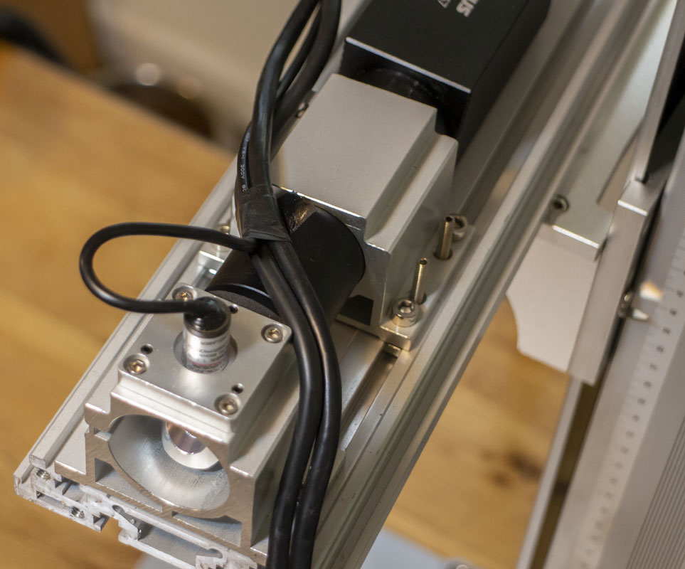
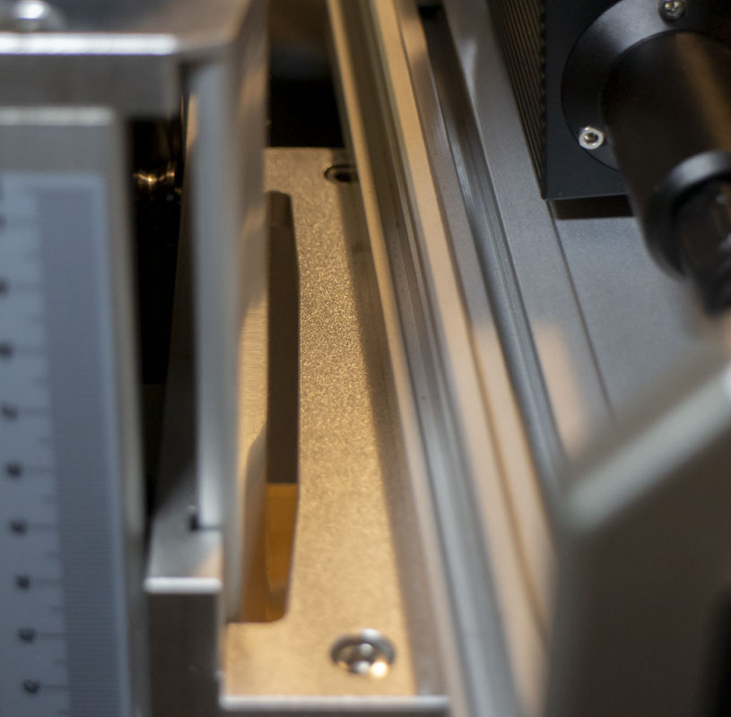
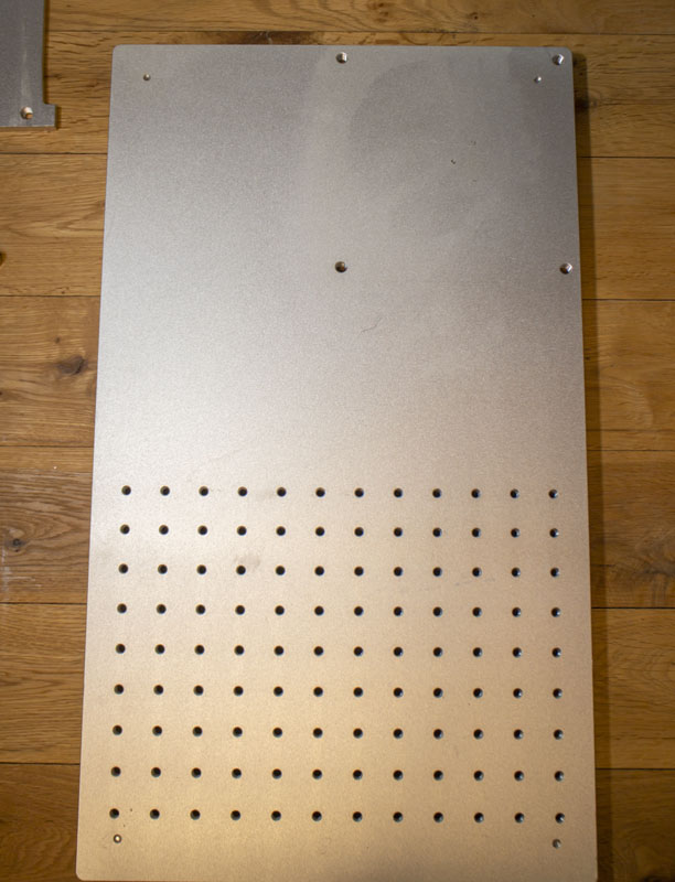
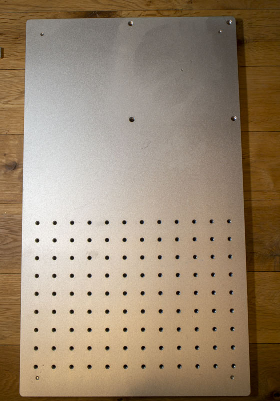
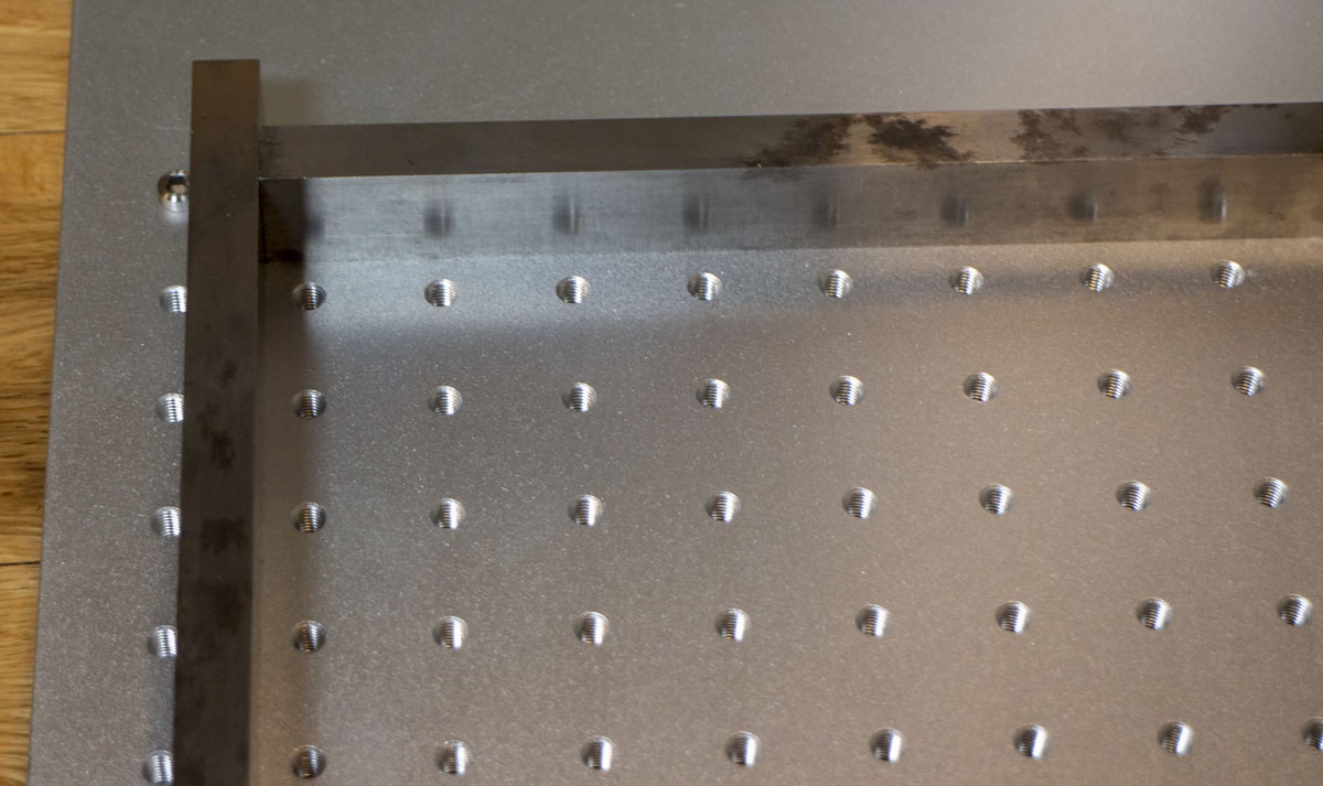
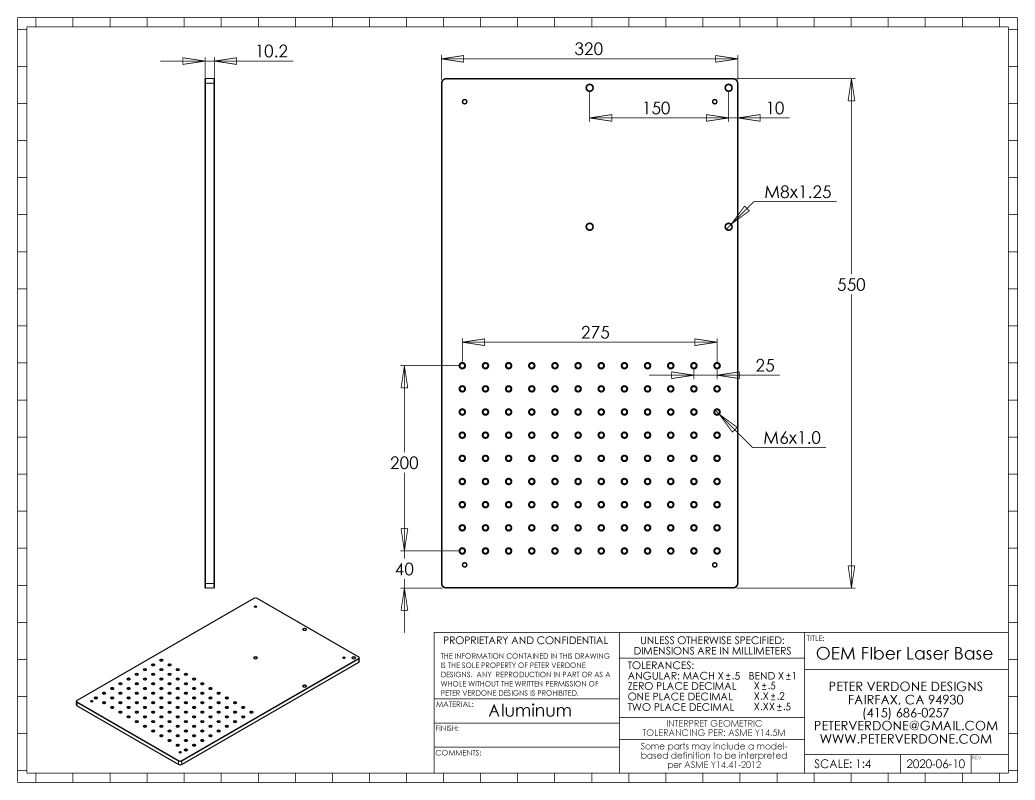
The base of the OEM setup is usable. It’s a big chunk of aluminum and has a well enough executed raster of threads. It is a fairly cheap optical breadboard style but it looks ok. M6 x 25mm spacing on part of the board. It’s thin, 10.2mm. I’m looking at ways of improving this whole foundation.
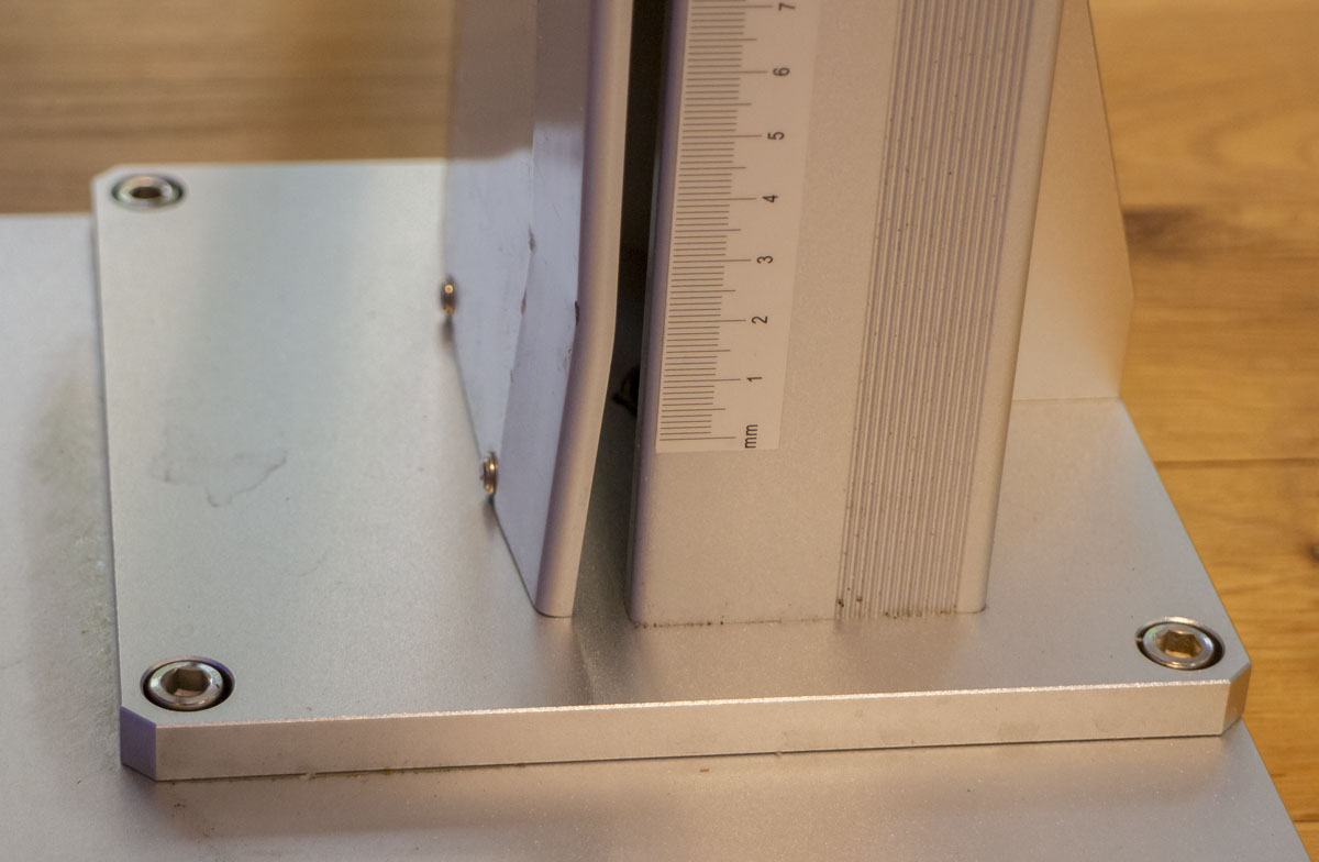
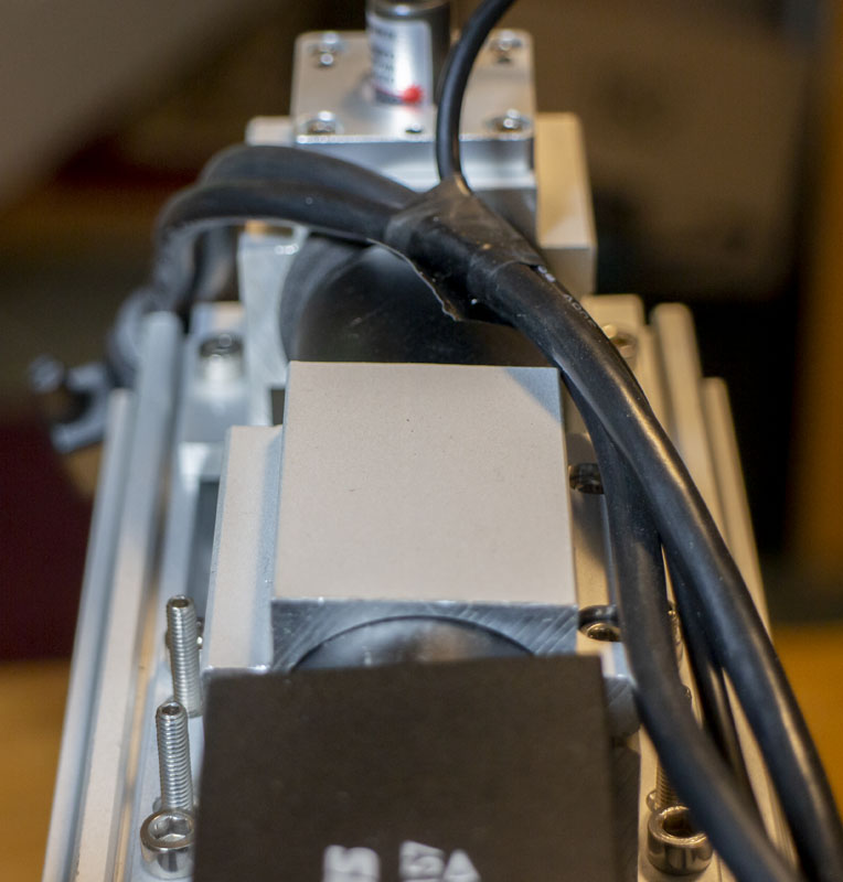
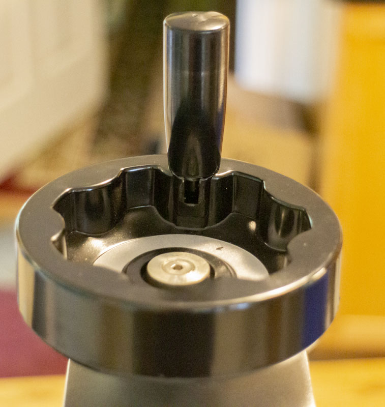
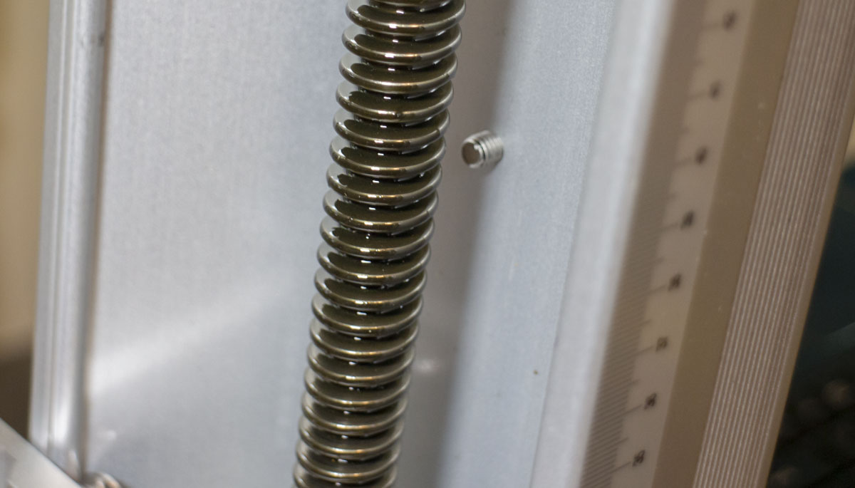
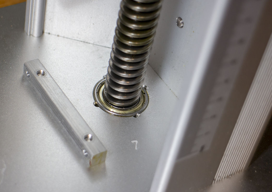
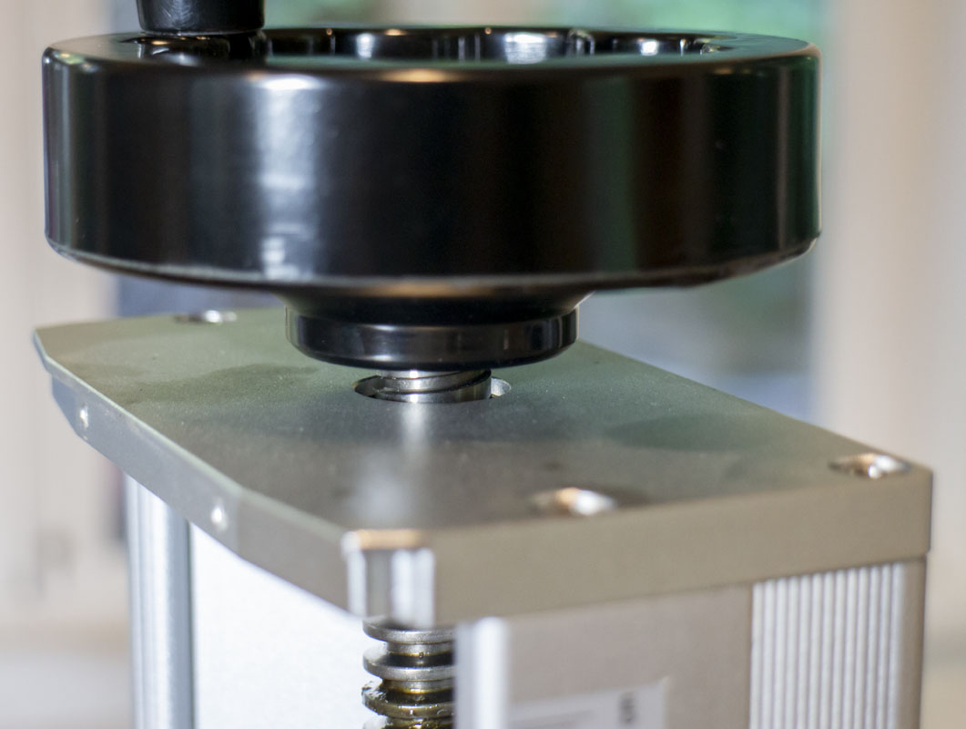
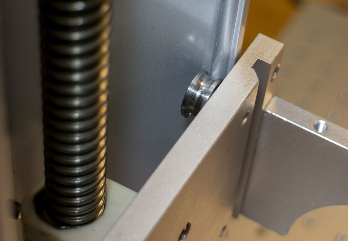
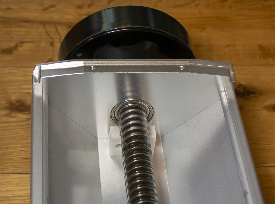
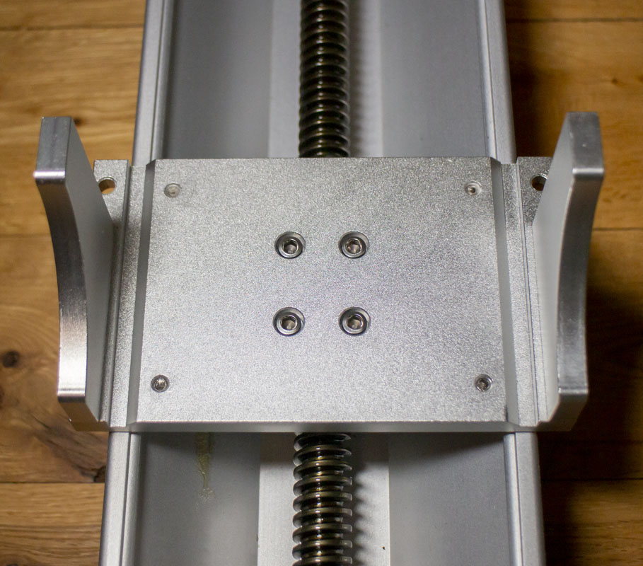
The big problem that I found with the whole unit (so far) is the tower and galvo alignment. The z-axis tower is very low quality and a bit rickety. Not what I’m looking for. It’s bearings are non-adjustable and ride on the side rails formed in the extrusion and as the extrusion bows, the fit gets loose. I’m going to need a replacement with something better and with a motor.
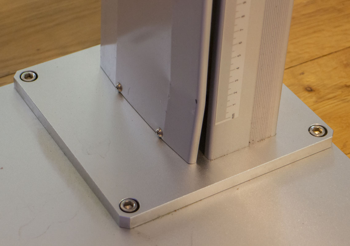
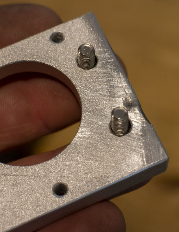
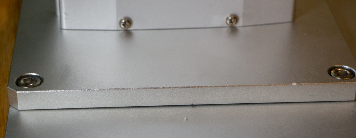
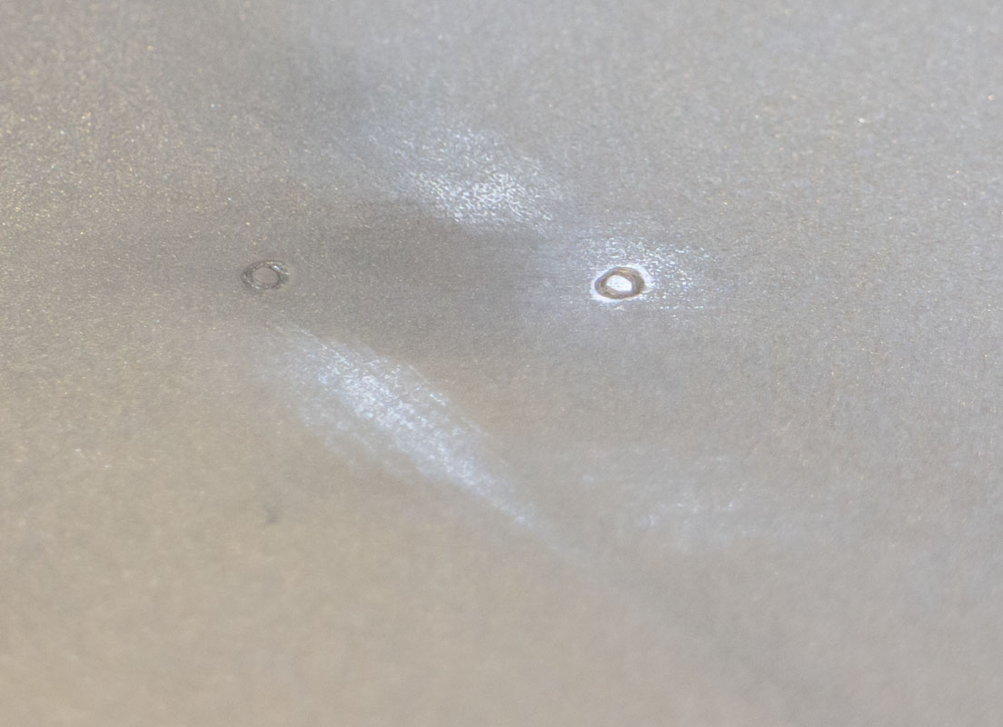
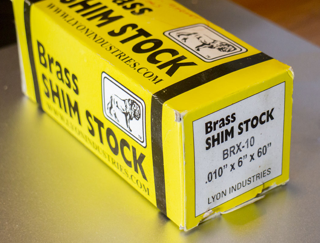
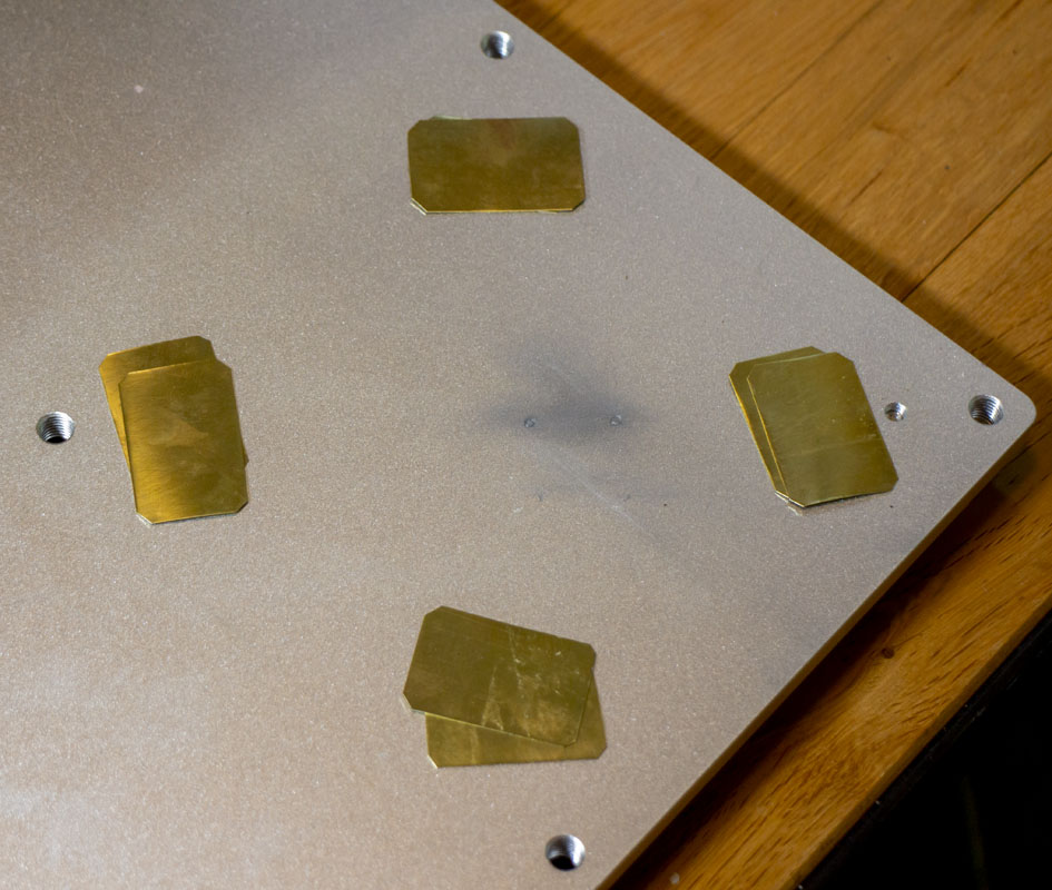
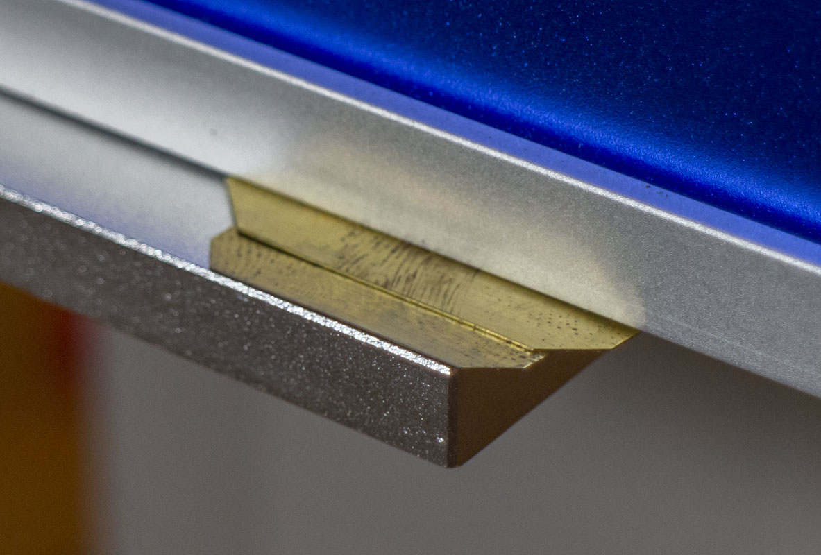
As if to add insult to injury, the set screws on the z-axis tower that help take up the play in the lead screw are slightly proud of the base. About 0.015″. This causes the whole unit to rock and tweak as it’s bolted to the base. Evidence of that is left as a mark on the base and some bow left in the adapter plate. To be expedient and get up and running for now I brass shimmed the structure 0.020″ to eliminate issue.
Aligning the galvo using the lens rather than the enclosure, I found that I needed to shim the emitter enclosure about 0.020″ at the front to get the lens within 0.1 degree of the table. Again, not super perfect but it’s a known quantity at this point.
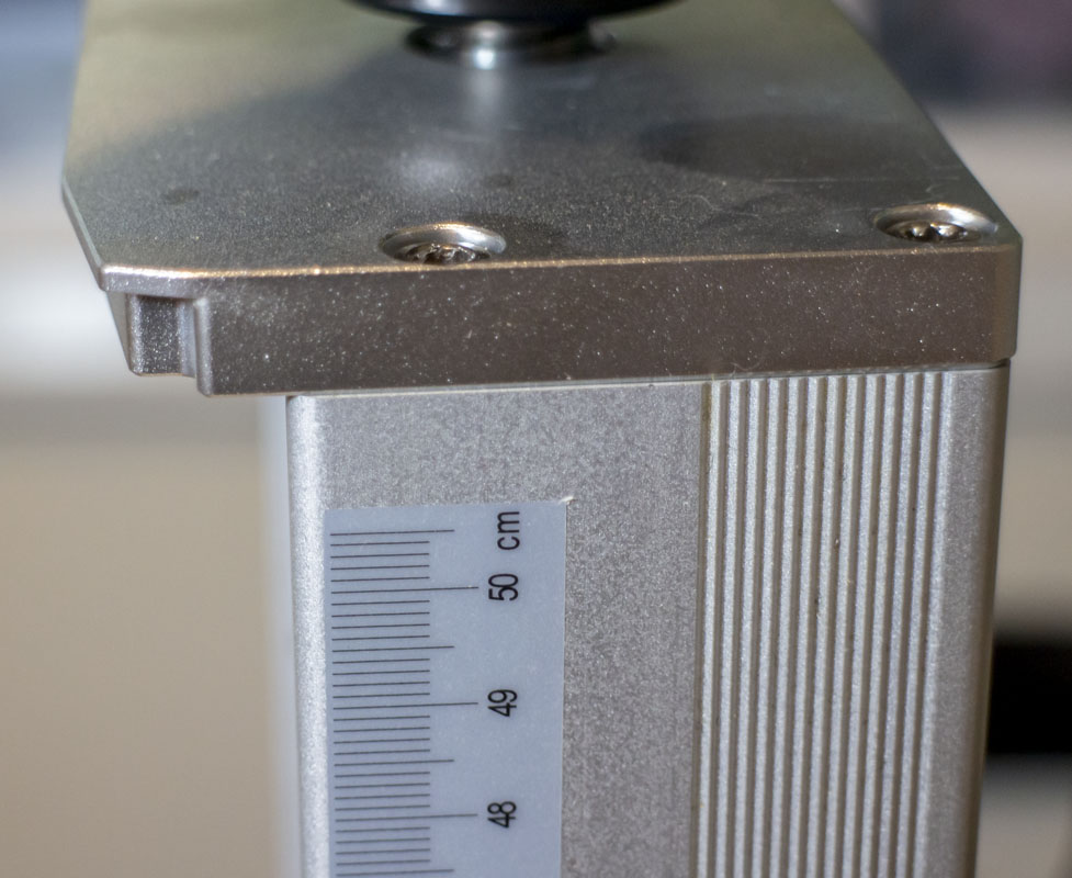
I’ll need a proper (but cheap) DRO for the Z-axis so that I can control focus very precisely. This will be a 3-axis DRO as there may be more robust positioning rails added at a later time. Shopping around it looks very affordable.
I’m going to use a cheap XY stage for positioning, 210x150x75mmm, 140x100mm stroke to locate my work. I may have to improve on this with proper rails and servos in the future. Getting good results from this system means centering cut as best as one can with the axis of the lens and minimizing projection to the corners of the projection square. Thinking of the work area as a circle helps with this.
To inspect the cut of the laser and ensure all of the settings are good, a small scope is needed. I got a Cainda F210. Setting the machine up well requires some magnification with lumination to see how each on/off timing setting changes the result. A cool thing about the scope that I got is that it will send images by wifi to my phone or USB to my computer. This makes recording to media or sharing easy and useful as the situation warrants.
Obviously, everyone is saying…”TURN THE DAM THING ON AND USE IT!!!!” Yup, not my first rodeo. I’m ready to go to the actual optical alignment and start some tests. That, in another post.
Thanks to JefferyJ for answering a bunch of noob questions as I got this all figured out. Good folks share on the net. Sharing is caring.