The stem is an incredibly important detail on a bicycle. It places the handlebar in the proper position relative to the bottom bracket and the saddle regardless of what lies beneath it. Where the stem holds the handlebars can make a bike fast on climbs, or fast on descents, or great for all day comfort. There is a key range where the bars can be placed in a specific paradigm and just a few millimeters can make a huge difference in the riders experience. So many myths and un-truths surround stem choice, from having a stem strut level to the ground to being able to see the front hub axle with your face close to the bars. Stem choice is very important and for many reasons. This post is not about how to find the proper position, rather issues with the hardware and specifications available.
I tend to use Salsa stems for getting just the right fit on a bike. Specifically, the Pro Moto 3 stems. They are 4 bolt stems that come in +7/-7, +15/-15 and +25/-25 degree rise/drop and 70, 80, 90, 100, 110 and 120mm lengths. This is an extremely wide range of positions that these stems can produce on a bike. That’s extremely important to me. Also, the stems are super cheap for me to buy at wholesale. The MSRP on them is $35.00 so you can buy a few to get just the right fit on the bike. I have quite a few of these. This is not wasted money. It’s critical to try a few stems to get the right fit. Also, you may use 2 to 3 different handlebar positions through the riding year, so you will need to make changes as needed. It’s also good to experiment with your technique and how you interface with a fit.
Note: In my experience; Salsa, Truvativ, and Profile Design stems are probably made in the same factory. They are very similar and can be seen as being the same.
Obviously, you can try using a Salsa Size-O-Matic II in a static situation. Honestly, I have one of these and I only use it when using a fit cycle to get X,Y co-ordinates for the bar clamp and saddle. Why? Simple, you need to hit the road/dirt with a stem (or fit for that matter) and get some time with it. You need to see how it works while climbing or descending or after 4 hours in the saddle. Fit bikes and stems can get you close but you can’t ride them. Only a ride can validate a good fit, especially when tested against several options.
There is an important caveat on my use of the Salsa stems here that I can’t stress enough. All cast/forged stems, no matter how much you spend on them have this issue. The faces of the stem that contact the headset and top cap are NEVER square to the steering axis. Ever. I machine this face square using a special arbor on a fancy Hardinge HLV-H collet lathe. This produces a face that are just a few tenths of a thousandth of an inch out of square without really trying. I’ve seen stem faces off by more that 0.007″ from square. That’s a massive amount of misalignment for a critical bearing system that holds the two halves of the chassis together. This reeks absolute havoc on the front end resulting in poor front end feel, shuddering, chronic loosening headset, short headset life, and noise. Most folks can’t do this the way I do, so be weary of purchasing cast/forged stems. J. A. Stein Company produces a handy tool that can help the professional or home bicycle technician face cast stems. I’ve never used one of these, but they will do much better than nothing.
Once you do get the right fit, then spend what you like on fancy stems. Carbon or CNC aluminum or magnesium are popular choices. My favorite high end stems are produced by L.H. Thomson. The folks there have been at this for a while and take immense pride in their work and their product. They are defiantly worth your attention if you are looking for the best your money can buy. I do wish, though, that Thomson would start making some higher rise stems as that I the type I prefer.
The Real Problem.
This brings us to an industry problem. Stems have traditionally been specified based on the length and angle of the strut connecting the bar clamp to the steering axis. This is a big problem. The end users probably don’t realize this but they are pretty ignorant of any serious consideration of bike design or fit. This really effects the fitter, bike designer, and the frame builder.
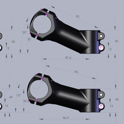
The supplied information will give us the handlebar offset from the steering axis, length x cos(angle). What we don’t have is the distance from the bottom of the stem to the handlebar. We can calculate the rise from the intersection of the steering axis, length x sin(angle), but we are never told how high above the stem base this intersection point is. Also, every design uses a differernt distance. Because of this, one stem of a certain length swapped for another stem of the same length will most often result in a handlebar height very different from before. I have never seen a specification for this.
In the past few years, Brent Curry (BikeCAD), responded to my request for more stem dimensioning in his program. Now there is a huge amount of detail we can match in a frame design.
Thomson does make an attempt to communicate their stem dimensions, but they do miss the mark with having all the necessary information; Thomson X2 Stem dimensions, Thomson X4 Stem dimensions.
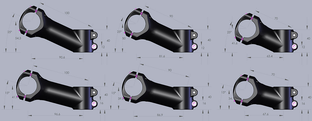
I made my own little array of the Salsa Pro Moto 3 stems and have shown all the relevant information I could need when designing a bike. All stem manufacturers should be providing this information. Sadly, none do.
As a designer and builder of bicycles, I need much more information than just angle and length to design a frame properly given a specific stem. I’m trying to locate the handlebars in just the right position and it’s gotta be right.
I’m going to send a link to this post to the folks at Thomson and see if they will make a comment.
Tim Krueger, the product manager for Salsa Cycles at QBP responded to my request for comment on this post. He sent me this email:
Peter –
Your email was passed to me. My name is Tim, and I am the Product Manager for Salsa Cycles.
I read your blog post, and I wanted to give you a bit of info. First, there is a reason manufacturers do not provide all the info, its not just laziness. Primarily, it has to do with manufacturing tolerance. On a 3D forged stem, based on how the pieces come together, there can be a +- 5mm tolerance in the length of the stem. As a QC step, we typically call out +-3mm as the acceptable range, but that can still create up to 6mm of difference from one stem to another. This does tend to freak some consumers out, but as you know, it is typical manufacturing. The very detailed drawings are not posted because then if someone like yourself measures and finds a discrepancy, they tend to call it a warranty situation. So the industry has gone to generally calling things by round numbers such as 100mm, and not specifying exactly where that is measured.
As well, the exact stems of ours that you measured and put up probably slightly fell into this category, because your dimensioning on your blog is not correct. Our Length is measured from the bar center, along the stem body center, to the theoretical intersection of the center of the steer tube. So this also creates variance in total length when factoring in the various angles of the stem, as that theoretical intersection with steer tube center moves down with steeper angles, and hence makes the stem slightly shorter in actual reach for the same reach measurement. Similar to how stack and reach are better frame measurements because head angle changes can make two bikes with 24.5” ETTs fit totally different.
Sadly, as you said, there is no standard in the industry for exactly how to measure a stem, and this creates confusion where guys like yourself who know what is going on, like to see the drawings. Not all companies measure like we do, in fact I know of one that actually measures length from bar center to the back side of the steer tube. Strange, but not out of the ordinary.
The final part of this is that our drawings are proprietary. They do disclose some parts of our design, and this is why we do not put them out on the web. Sure, for a $30 stem, worrying about our competition is probably not an issue, but as you know, we are part of QBP, and we have a general policy to not disclose our proprietary drawings, so even for a relatively small inconsequential part such as a baseline stem, we still do not do it. If it helps you at all with what you are doing, I am willing to send them to you with a confidentiality agreement to not post them on the web. I have been a follower of your blog for years, and while I don’t always agree with all of your positions you put out there, I really enjoy that you have convictions in your opinions, and that at least someone is out there thinking differently about our industry. In my job, I am pretty split as on the professional side, I adhere to a lot of the industry norms that are sometimes super frustrating, but I also have a garage-logic craftsmanship thing that I do on my own side. You seen that new clamp thing to adapt Leftys to Fat bikes? That was me and a buddy who started that out, making ugly blocky samples. That’s another thing I noticed from you all the time – you are a way better machinist than me. My first creations are typically pretty hideous.
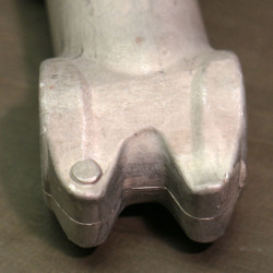
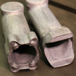
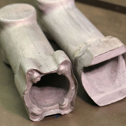
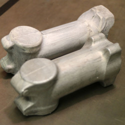
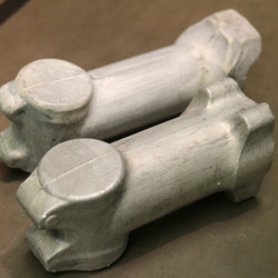
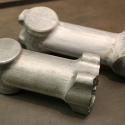
Also – if you are still curious, I have a bunch of raw 3D forges on my desk from various stems – to show your class about the manufacturing process of a stem if you wish. Its pretty cool because even though a manufacturer says “3D forged construction”, there is still actually 4 different CNC steps to take it from this piece to the finished product, and then of course there is finishing such as blasting, and anodizing and laser etching. The other cool part of 3D forging, that I have yet to understand but plays into the length tolerance – is that they will use 1 piece of forge tooling that is somehow adjustable to make 70/80/90 and another piece to make 100/110/120. They tell me that there is some special kung fu with the final punch that pushes down the center of the stem, but they guard their process pretty tightly. Believe it or not, there is only 1 company in Taiwan making 3D forged parts for the bicycle industry, and they guard their “technology” pretty close. It’s a cool place to see though, because there are some machines that are running 24/7, and they are all lined up, one making FSA, one making Bontrager, one making Truvativ, one making our parts, and many others. That’s also the beauty of this process, most stems from places such as Ritchey or Truvativ are actually all the same base forge, they may just put a better quality alloy in for a higher level product, or add additional finish CNC time for a better product to pull out a bit if weight.
Anyway – lots of info on this subject, and I could talk for hours. Feel free to shoot me more questions, I would love to help you with anything you need.
Tim
Oh yeah, one thing to add – in this part –
On a 3D forged stem, based on how the pieces come together, there can be a +- 5mm tolerance in the length of the stem. As a QC step, we typically call out +-3mm as the acceptable range, but that can still create up to 6mm of difference from one stem to another. On the drawing, we prescribe the acceptable tolerance, and the supplier throws out anything that is outside of the tolerance range. This is where the tolerance comes from, as you make the tolerance tighter, there is more scrapped product, and the price goes up. This is why higher end products cost more, its not always about material, sometimes its about how finite the window is for manufacturing.
Reverse Engineering.
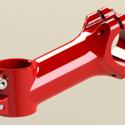
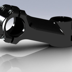
To solve a recent issue having to do with a road bicycle frame design in SolidWorks, I needed an accurate ‘real world’ stem model. That’s where this post began, along with systematic problems with stem dimensioning.
I love reverse engineering parts and assemblies. When I describe this process to students, I take pains to have them understand that the part that exists virtually in their computers should be an ‘exact’ virtual copy of the real world item. A close approximation is not acceptable. The devil always lies in the details and that’s why having the real artifact in hand is important, it’s the measure that ensures that you can’t take shortcuts or cut corners.
There is so much to learn with this process. You have to step into the mind of the engineer or designer of the piece and look through their eyes. Determining if they were working with metric or imperial measures or both, if they were systemizing their approach or just grabbing any number that came to mind. Where did they engineer and where did they design. It’s a fantastic way to learn more than you ever expected about the subject as well. For instance, my modeling a chainwheel and cog many years ago gave me an understanding of chain driven gears that I value dearly to this day. In this current stem example, I learned that the 6mm bolts for the steerer binder are non JIS special bolts.
You also develop manufacturing skills. In a strange way, you have to figure out how the part was made. What processes were used? Was the positive of a cast part machined or printed? What could the order of operations have been? All are clues as to where the part came from.
Another benefit of reverse engineering with whatever solid modeling package that you employ, is that you are pushed to use tools and techniques that you typically don’t use. You have to figure out how the original designer was able to produce their model and duplicate that. Here, the ‘spun and cut’ strut of the stem were peculiar given this would end up being a cast part. Very cool. Which fillets were done before others to ensure the model doesn’t crash?
Reverse engineering also teaches you new and interesting ways of measuring as you aren’t working with original documentation. You have to figure out what the driving parameters are and how to measure each odd detail around the part. Especially interesting is when you are doing this in your kitchen at night with just a tape measure or crude scale at your disposal. I’ve done very accurate models using impossibly bad measuring tools used in creative ways.
Students and novices should put a considerable amount of time into this process and develop their skills. Spending just a half hour modeling a new thing will teach something valuable.
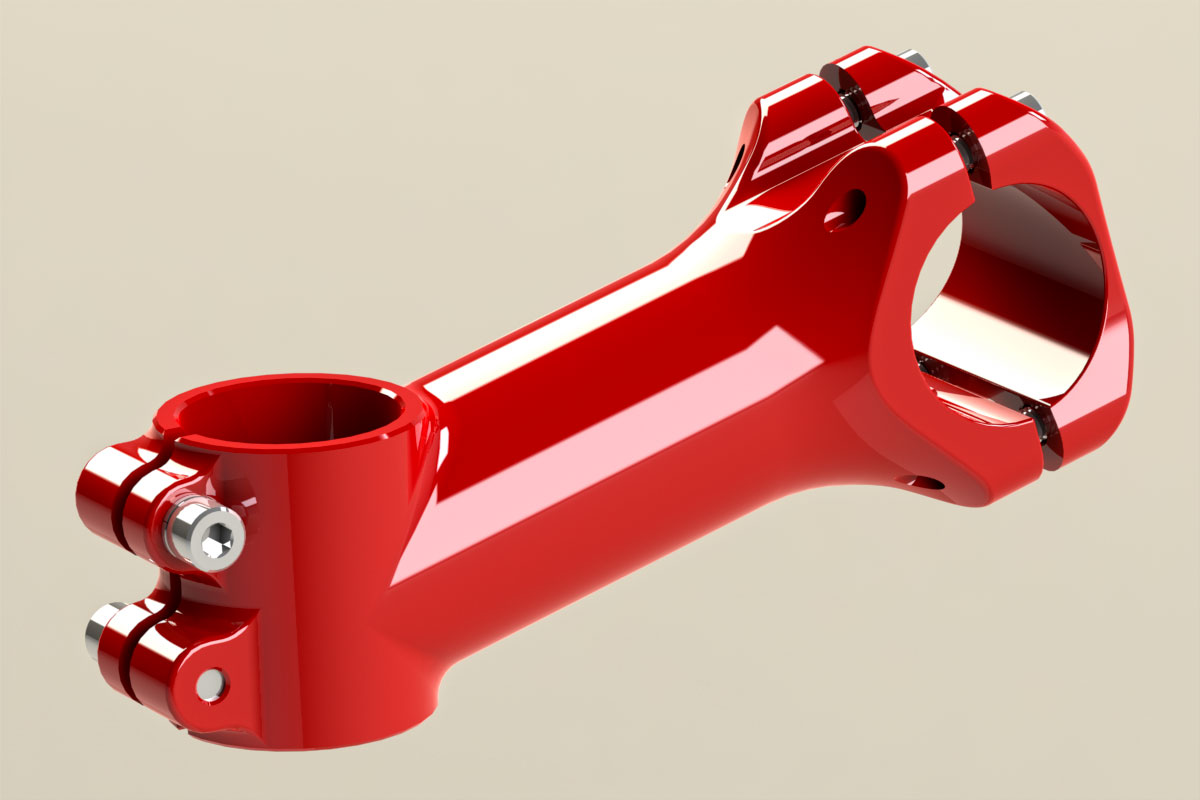
After producing real quality models, you then have access to a library that you can draw rendering or perspective vector line art from. This is great stuff for dressing up documentation and showing that your work is serious.
Please note, I really suck at rendering.

FYI, my model tells me that the mass of the 100mm x 15 degree stem is 180.95 grams. An actual measure is 167g. I obviously have some issue with my model or the applied materials that needs tracking down. Much of this is coming from a manufacturing vs. theoretical joint of the strut to the steerer binder. Also, my actual has a steerer binder that measures 41mm rather than 40mm. Nice to have an easy fact check for myself.
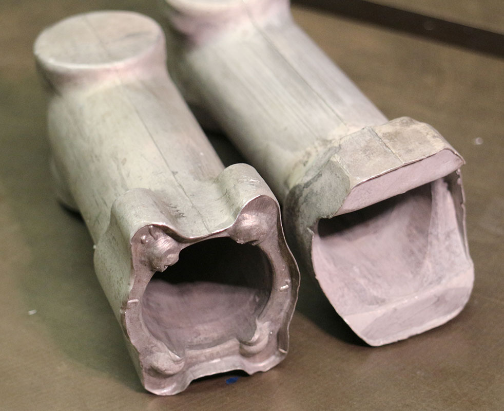
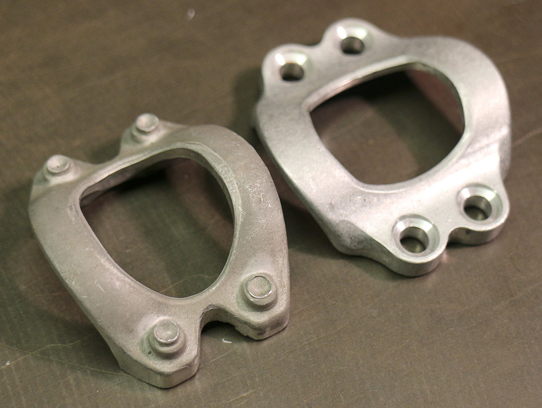
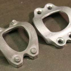
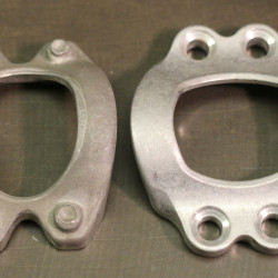
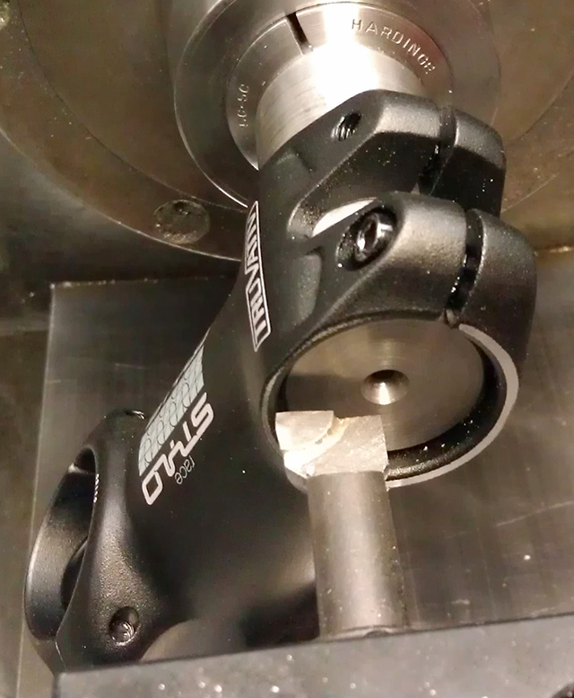
3D Forging
Here are a few images of what a raw forged stem looks like prior to any finish work. Pretty cool. Tim from Salsa sent these in to share.