
Let’s talk about the front of the bike. This has been the part of the bike getting renewed attention in the past few years. New stem products and 32″ wheels have gained some traction in the mountain bike marketplace. As these encroach on what I’ve been doing for so long and do the most advanced work with, I take notice. I listen to the discussion. An opportunity to see a new perspective can exist in the most absurd places. Then, a stupid comment on a PinkBike thread drew me into the fray. I commented. Between this and another lunatic essay read elsewhere, I was inspired to make this post.
It has been difficult watching ‘media’ and the folks selling this stuff. They seem to have no understanding of how these work within the ‘designs’. There are a lot of words slung, hands waved, and ‘sick edits’ but no real substance in the argument. I’ve also grown tired of hearing myself say, “Show me a setup print!” It’s strange that so little work is so impossible to produce.
Front end geometry is a topic that few understand. So that it’s clear what the point of all this is, I’m going to have to back us up to the the more foundational concepts before getting into the specifics at hand. All of this is valuable for the uninitiated.
Anyone working in these spaces looking to validate their claims would have to produce a setup print. No serious discussion of bicycle geometry can take place without one, especially one involving the hand grips and front tire. What I notice in EVERY mention of the new stem products and wheel diameters (or anything geometry) is an utter lack of setup prints clarifying the changes made. What claim can be made? There isn’t a discussion of geometry that I’d consider serious. This demonstrates the level these folks are actually working at. And that’s not good for them.
Produce a setup print! If you are an athlete, or build bikes, or want to win an argument, or look for higher levels of performance in your bikes, you MUST do this. The change it produces in your understanding will astound you. It changed everything in what I do. I’ve attempted to disseminate an easy way for folks to do this in the past. Few noticed. It depresses me.
Just drop this file into the dimensions folder for your install of BikeCAD to give you a template similar to what I use. Here is an approximate path: C:\Users\CHANGE_NAME\BikeCAD_23.1_configuration\DIMS
http://www.peterverdone.com/wp-content/uploads/2026/06/2026-06-07PVDFlatBarDimensions.bcad
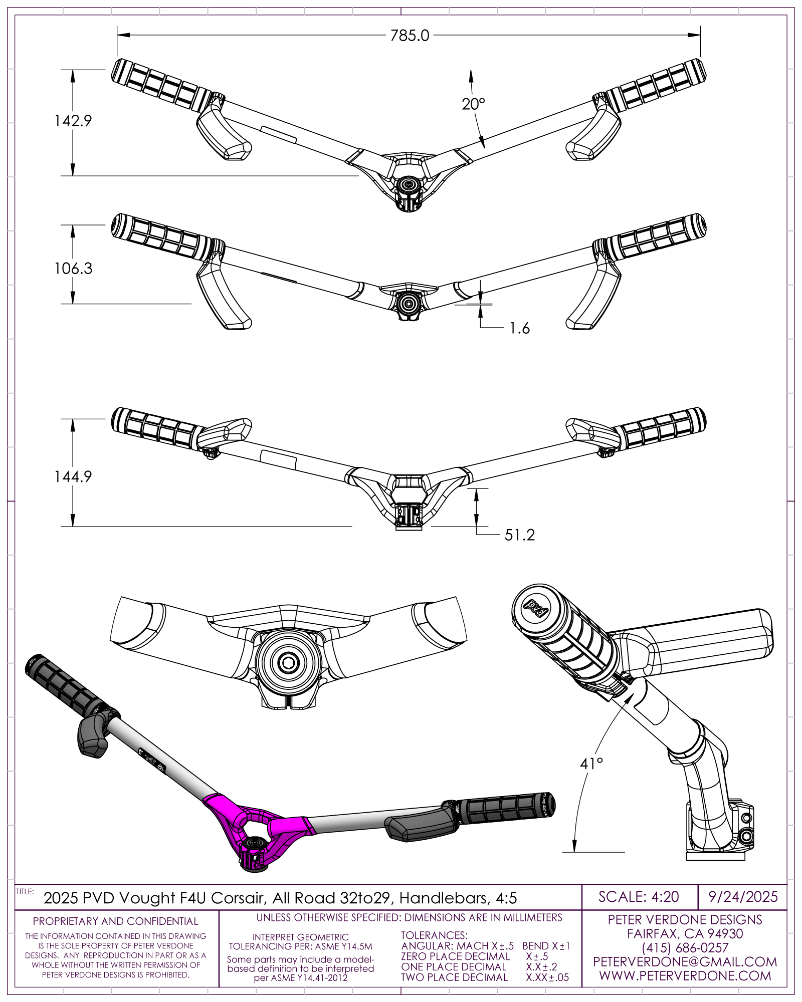
Below is a pair of setup prints from my most recent bicycle project, the 32/29 Corsair. I would accept either of these from someone wanting to join in this discussion, depending on the modeling environment they work in. The first is from BikeCAD and the second is from SolidWorks. Any 2D or 3D CAD platform could be used to produce something similar.
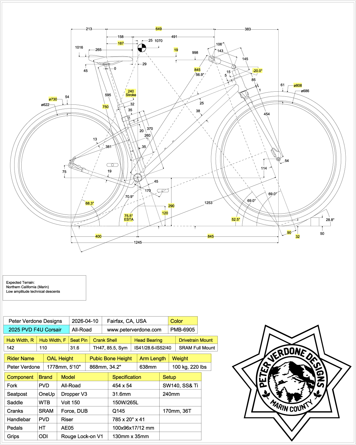
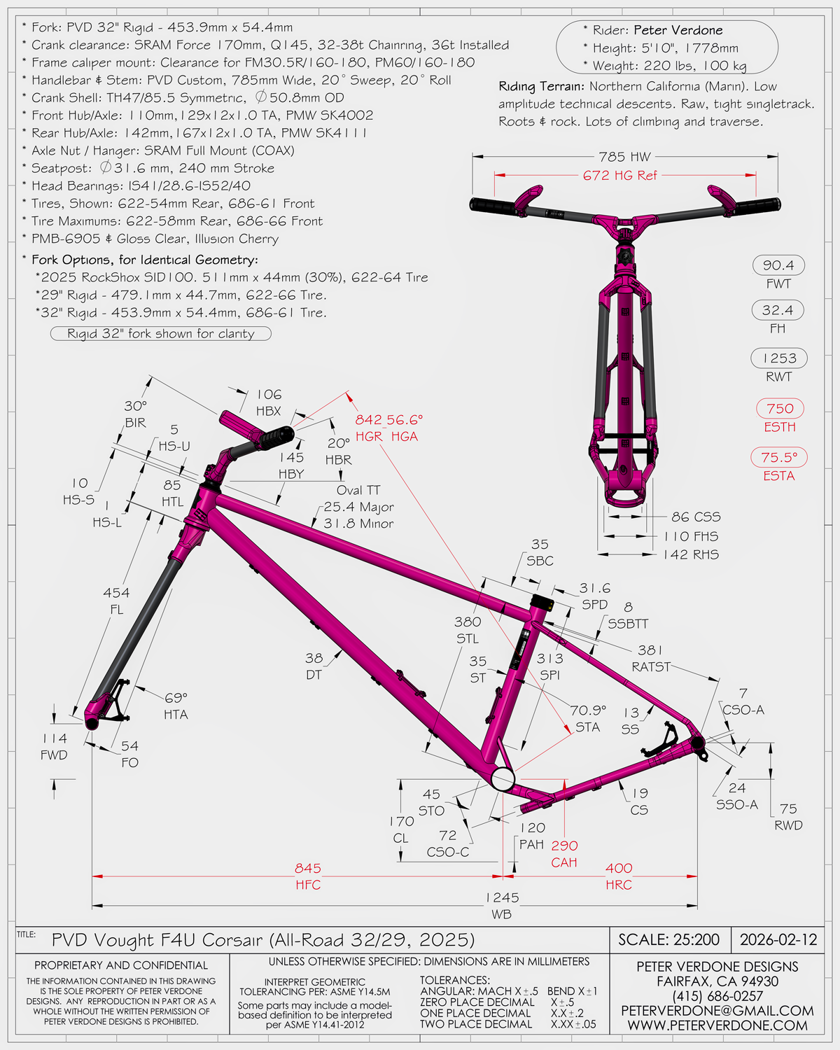
You’ll notice that these setup prints document critical details of the development program:
- Rational, engineering based geometry parameters
- The locations of both tires
- The tire and rim sizes for both wheels
- The saddle position, made clear relative to the crank axis
- The hand grip location, made clear relative to the crank axis
- Handlebar geometry, with pitch to horizon included
- Handlebar geometry is reasonably accurate to the real thing
- Headset, spacers, stem, and bars are precisely documented
- Crank information, including length and q-factor
- Travel and JRA sag noted if suspended
- Dropper stroke noted
- Dropper insertion noted (and validated)
- Information about rider size and mass
- Expected terrain or use of the bike
- Additional detail or notes are a bonus
You’ll notice that you don’t see many of the terms that marketing people like to use: stack, reach, ground trail, BB drop, top tube length, effective top tube length, upsweep, etc. That’s because those are not valid parameters for understanding the bicycle. If you’re using these terms… stop. More, folks that use those terms most often don’t value the location of the front contact patch or hand grips….parameters that really do matter.
I show stem geometry in a setup print for documentation purposes, but it’s not a performance descriptor. This tends to be confusing as I say that stem length has no meaning…but it is needed to produce the setup and tracking changes. For folks dealing with commodity setups, predictive stem choice will produce the correct connection of the handgrips to the front wheel. This requires documentation to arrive at correct setups. This can seem like a mixed message but for folks that have gone through this process a few times the distinction will be clear.
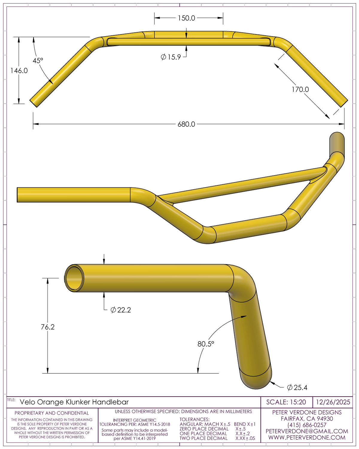
Accurate handlebar models are CRUCIAL to do all this. Most drawings of ‘bikes’ that I see, if bars are even shown, are painfully erroneous and add only misinformation. Without a good model of the bars there is no way to know where the grips end up. The change of one bar to another is not trivial and can dramatically change how a rider interacts with the bike. I shared significant detail about this back in 2019
From the setup prints, we can then dig deeper into the fundamental handling geometry of the bike. Notice that this is a remarkably simple system to show in 2D. Close your eyes. Think about how your bike feels when you steer at slow speeds. This (below) is what it feels like, isn’t it?
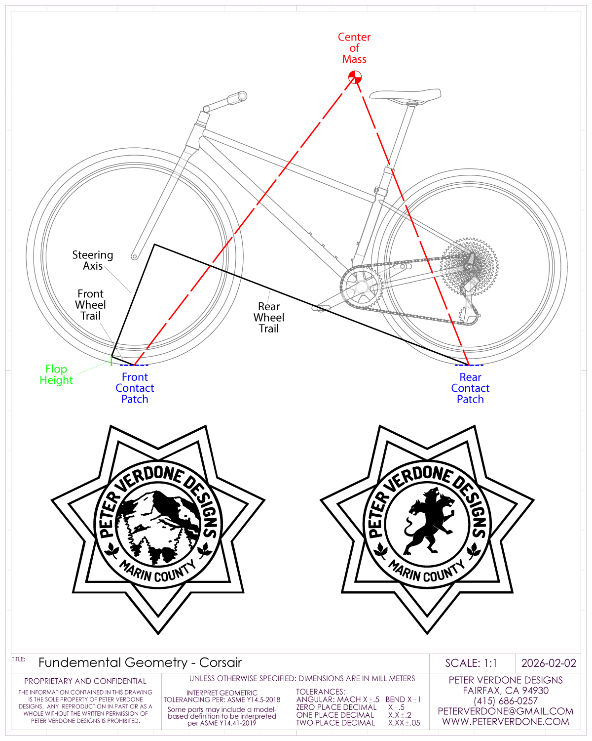
Notice that the location of the wheel axles are not important. Nor is the diameter of the wheels or tires. They’ve been digested, showing their product. We are looking at the contact patches and the center of mass (COM). We’re also looking at the wheel trails (front and rear) and flop height. This is why geometric descriptions that discuss the axle locations or tire diameters should generally be disregarded and considered fraudulent.
Contact patch is a crucial concept to think about in the context of the front end. Without the friction produced by the contact patches, the system slips and falls over. More, the potential that is inherent holding the trailing arm from the ground is maintained when the frictional trailing torque or torque is applied at the bars overwhelms gravity.
Keeping track of tire size is important as it describes the shape and scale of the contact patch. Larger diameter, wider, and knobbier tires produce larger contact patches. These produce higher frictional force than smaller tires. That is all valuable to remember.
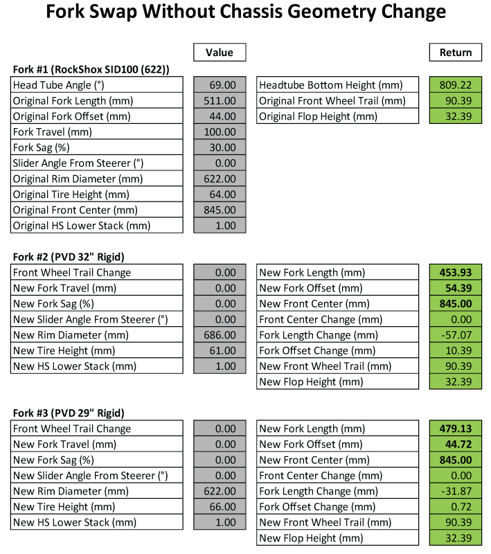
Keeping essential front end geometry similar with wheel size changes is relatively trivial if full control of fork geometry is afforded. This won’t account for inertial mass of differencing wheels or contact patch shape and size but geometric equivalents can be made. Notice that other than adjusting the length of the fork to keep the head angle and height fixed, adjustments are made to the offset to keep the same front wheel trail and flop height.
Arguably, the most important system detail is the distance the contact patches are from the center of mass, relative to the ground surface and earth. Looping is a primary concern offroad. This happens when the location of the COM, normal to earth, is ahead of or behind the contact patches. Going downhill, the system is less likely to loop forward (OTB) the farther the COM is behind the front contact patch. Going uphill, too steep of an angle from the rear patch to the COM results in plowing (sliding front) or looping over. This is easy to test by evaluating how much effort is required to keep the bike planted.
The angles formed by the mass-to-contact patches give us the mass components of weight over the tires in various conditions. Moving the front wheel farther ahead of the COM reduces the approach angle that the mass has with obstacles like rocks and roots. This will help smooth the disruption and speed the bike. This also keeps the normal mass behind the front wheel when going down steep trail, resulting in traction distribution to both wheels at a critical moment, maximizing control. Similarly, in the rear, the shorter the distance of the mass ahead of the rear wheel, the easier it will be to move that end around, while keeping mass over the rear for climbing traction.
These angles can also be reduced by lowering the COM. This is why we generally strive to set the system COM as low as possible. It plants the bike. While many factors contribute to the system COM, the height of the crank axis and hand grips have the most effect. Navigating the needs of the riders fit and what will improve handling is difficult as they may work against each other.
A quick word on COM that those outside of performance motorcycle development may not know about. Back in the 1980s, significant testing was being done to get the COM of the system as low as possible. To achieve this, fuel tanks and other heavy bits were placed close to the ground. While the goal was achieved, the bikes handled far worse. Why? Simply, bicycles and motorcycles do not lean over from a point on the ground. They kick the wheels out from beneath the bike so that the lean is actually rotating about the COM. This is similar to what is seen when balancing a broomstick over one’s hand. By shifting mass so low, the rider was now swinging wildly and less able to control the bike. The bike felt heavier. For this reason, development moved to mass centralization where the bulk of the system mass was focused about one particular point that helped the rider and the system.
In the bike’s geometry, those angles are the relationship that we pointing to when we say “front center” and “rear center“. While front and rear center are typically described as the direct measurement from the crank axis to either of the wheel axles, they are most precisely understood by the horizontal components. These are extremely valuable parameters to understand in the design and setup of a bike. It’s how the COM communicates to the contact patches. In reality, this is how we size bikes. even as commodity stems and bars limit choices for most.
In the real world the complexities of adapting a human to the bike is where the devil lives. Handgrip location is really not described or documented in the current era, though it’s crucial in that human-bike interface. Also key is the type of riding that human will do and where.
I produced a print to help us discuss the practical details of the front end system. I’ve approximated the location of the COM, a critical factor here. This is close enough for this example. (I have to readdress this myself soon.)
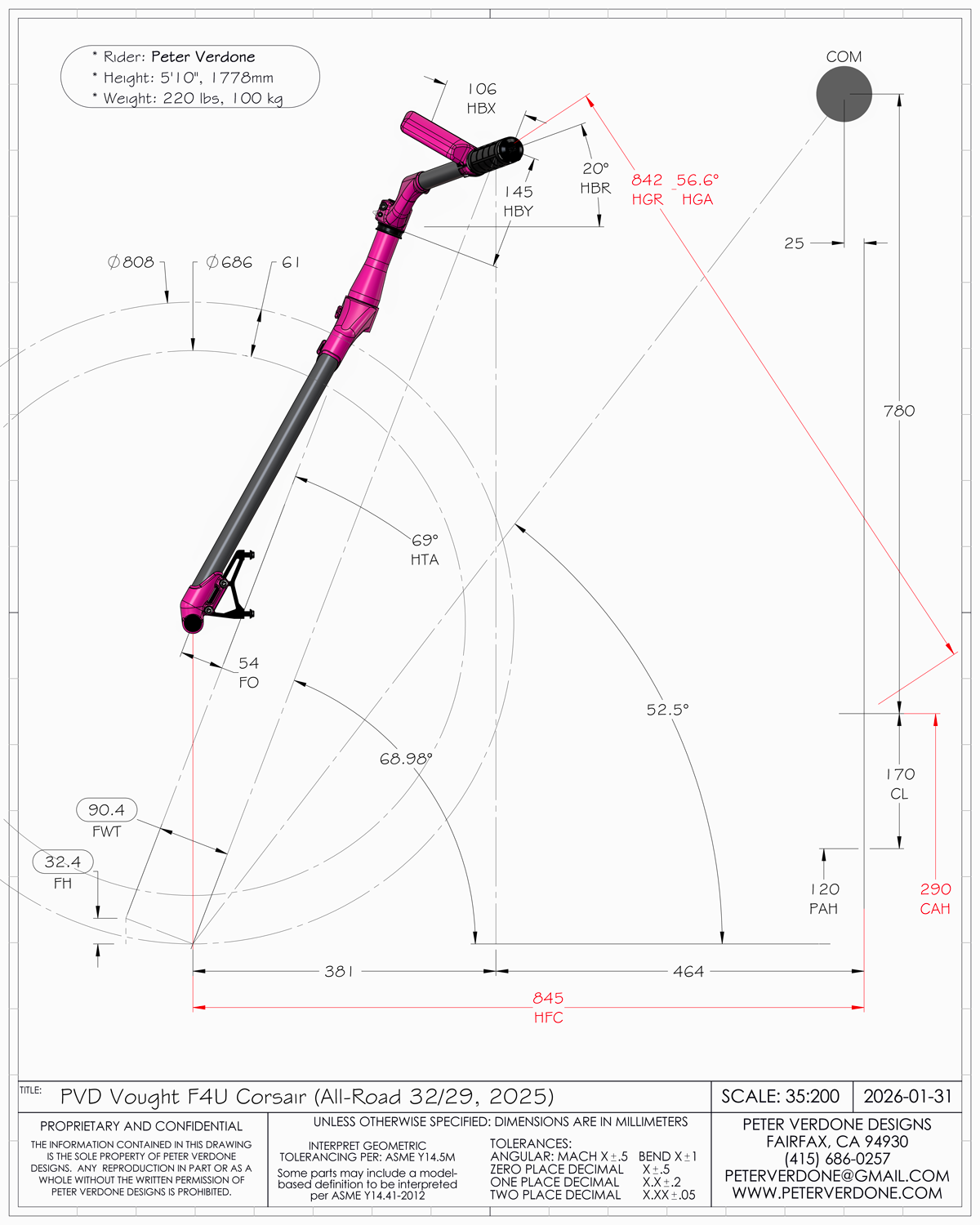
Looking closely at the print above, the tire’s interaction with the system is influenced primarily by the relationship of the system’s COM to the contact patch. The rider is typically riding (in attack) standing on their pedals, with 100% of their weight on them. They can rotate the wheel through torque at the grip and front wheel trail lever from the head axis.
When riding on trail, the rider is influencing the system through the location of their COM and torque produced at the pedals, saddle, and hand grips. Obviously, lean angle of the bike is a huge factor but we are going to work simply here and forgo this. They can change the weight on the front tire through the handgrip relative to the front contact patch. In dramatic situations, the hand grips can be pushed against or pulled upon to move the rider’s COM away from the crank axis along the gravity normal plane. Since the rider’s mass dwarfs that of the bike, the rider can also pull or push the bicycles COM from their own.
What should be clear is that the location of the contact patch and the location of the handgrips (and system COM) are connected to each other geometrically, so things like the shape of the stem, bars, or location of head bearings mean little. Thus we can make advantaged choices about where each should be.
To maintain ease of controlling their body, the rider is generally trying to keep their COM over the crank axis normal to earth. Uphill, the rider is trying to move weight forward over the bike. Downhill, the rider is trying to move their weight rearward over the bike. Generally, this is keeping the rider’s COM over the crank axis normal to earth. Throughout the translation from one attitude to the other the setup should allow the rider to (as my friend Ian Massey would say) ‘recruit muscle groups’ for optimum power, handling, and control in specific performance arenas and at the correct times. Said more simply, the rider moves around a lot and needs space to do that well.
Cross country riders need a different range of motion than a downhill rider. A trail rider who is bad at descending may want a bike that advantages them in that space to compensate for the deficiency, and vice versa for the downhill rider. That said, in general, people looking for more performance climbing will will have hand grips lower and more forward of the crank axis than those optimizing for descending.
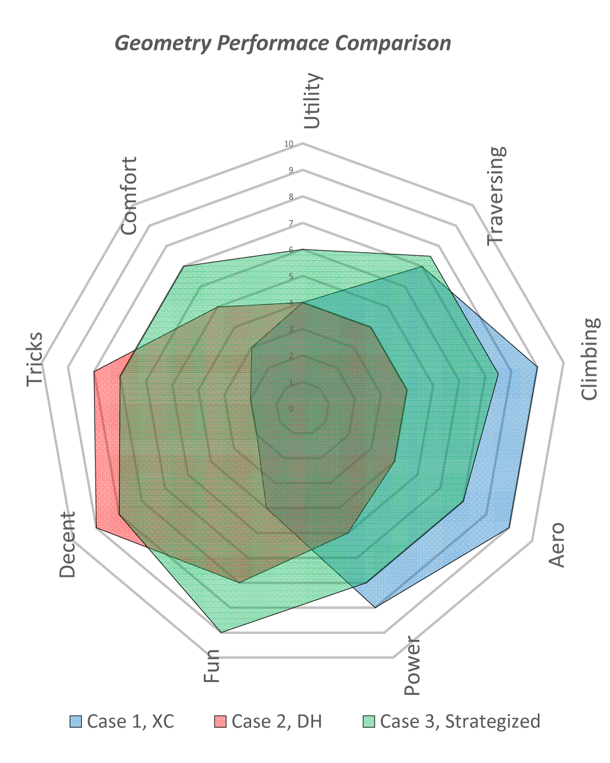
As I show in the spider graph above, only at the performance limits do we end up with setups totally undesirable in other cases. Most of us would like to have a bike that works well in a very broad range, even if it isn’t the absolute best for just one case. Especially for descending, the most extreme situation may only be 00:00:00.3 of a 04:30:00.0 ride. Does it really make sense to make most of that ride suck to be optimized for a fraction of a second of it?! Gravity racers or extreme riders may make this choice but most wouldn’t.
I was aided in my study of bike geometry by where I live. In Marin, CA, one needs to do a lot of climbing to get to the sweet downhill trails. I’m terrible at climbing. I’m heavy, weak, and get no enjoyment from that kind of suffering. What I could do is be stoked going downhill and survive enough crashes to figure out how to do that well. I worked a lot with setting up a bike that worked well going uphill and well enough going down. Balancing these needs led to different bike shapes. Once I was designing my own frames, they started morphing well beyond the norm. The adoption of the dropper seat post (around 2010) helped this immensely. Always with the same goal: get me up the hill as painlessly as possible so I could go down. I think that a lot of people would like a similar bike but end up buying something that’s terrible for both.
Constraints drive innovation and creativity!
Getting closer to the topic at hand, many people are confused about what stems do and how we use them in the design of a bike. Contrary to popular belief, the length of the stem has almost no effect on the front end geometry…if hand grip and contact patch location keep a consistent relationship to the crank axis. When a bicycle system is being designed, the stem geometry is merely a resultant. We place the tire along with the front wheel trail, flop, head angle (for suspension optimization), and the hand grip location. The bars and stem are simply connecting the dots (and axis).
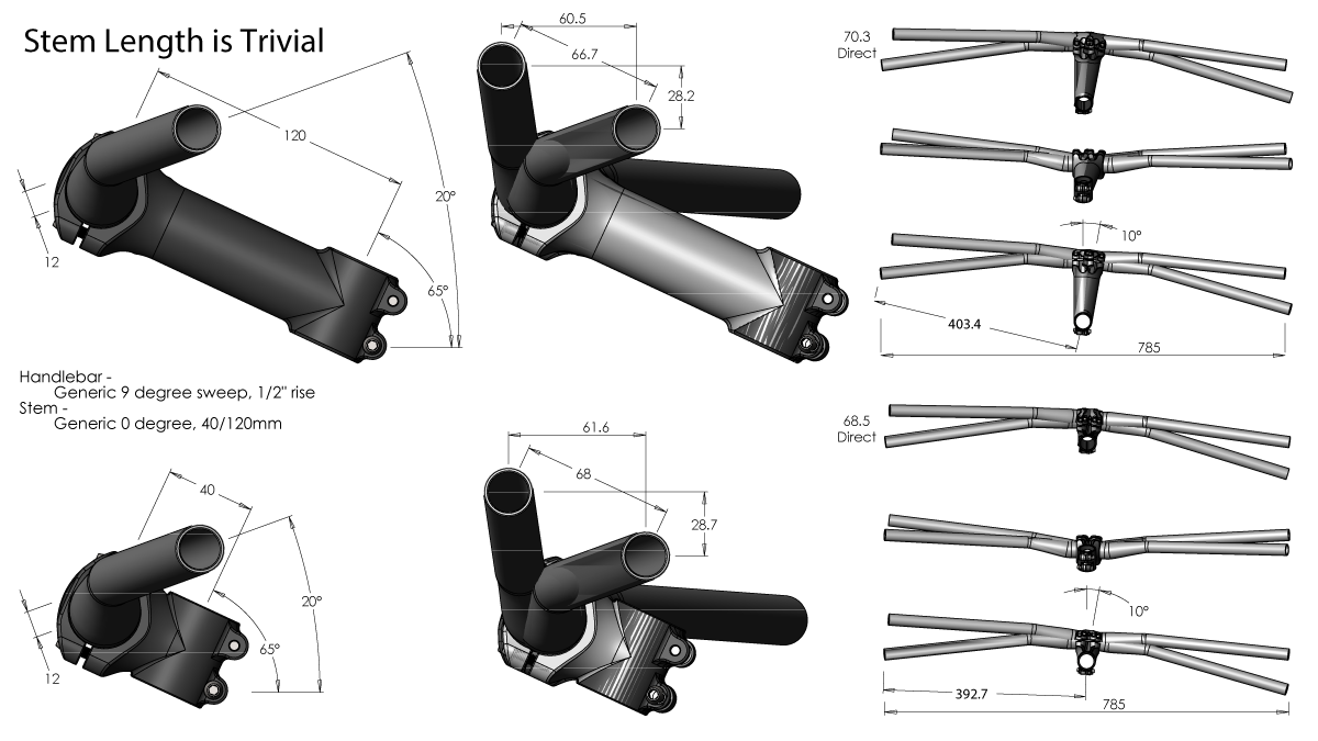
Below is an old graphic that I produced in 2015. It shows the difference between using a 120mm and 40mm stem, a 300% change. If the hand grips start at the same location within the system, you can see that the differing locations after a 10 degree turn is fractions of millimeters. I challenge that ANYONE could feel that while bombing chunky trail, if ever. The only real difference is the actual leverage (torque) about the head axis, for which the 120mm configuration has 3% more!
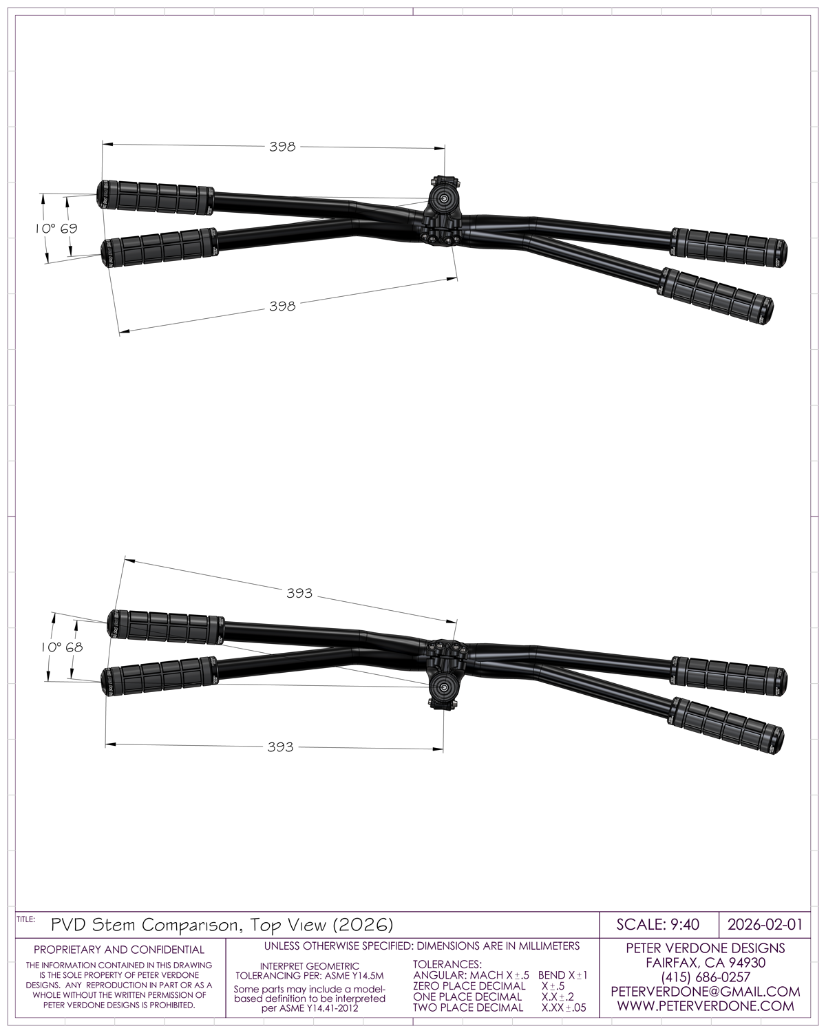
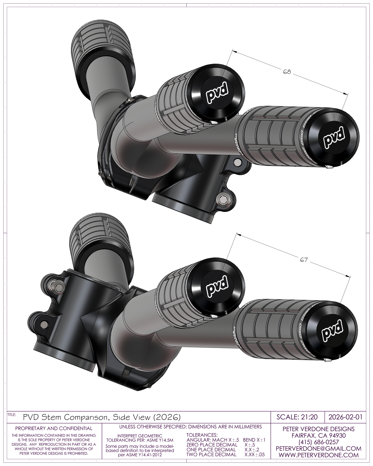
Here’s another demonstration to prove the point: a print that shows how a forward facing 35mm stem and a rearward facing 35mm stem differ practically. A complete positive to negative change. Again, if the hand grips begin at identical locations, the difference between the resulting location after a 10 degree rotation is a tiny rounding error. But again, the unexpected, the reversed stem has 1% more leverage than in the other direction.
What’s funny in 2026 is that the drop stem has been discovered by the lay enthusiast. This as 32″ wheeled and suspended bikes need to do significant gymnastics to place the grips. Why funny? We were using these stems back over a decade for Marin trailbikes. We were playing tricks with them that still haven’t been discovered by others. I think that the key takeaway here is that these ideas that many are discovering now are very old to those that have been working at a higher level.
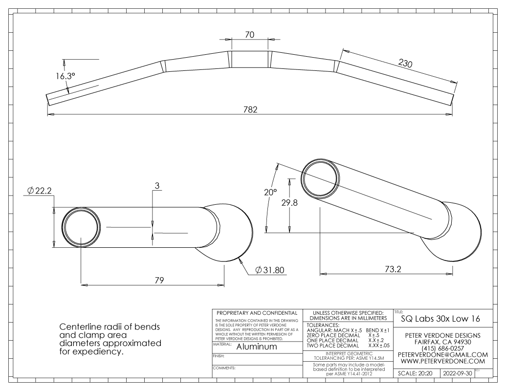
If you’re reading this and want to cut to the chase, imagining that you are working with commodity parts, there is one handlebar that I recommend. It’s the SQ Labs 30x 16 degree bar. Moving to this handlebar is one of the smartest setup choices one can make. Notice that the grip end is 79mm from the clamp. This provides far more setup choices than you would have with most other handlebars. Moving to this bar means that you will increase your stem length 25mm….or your bike length 25mm. Your choice. Now you have one.
Now let’s talk about head angle! Oddly enough, head angle isn’t a very important dimension in a bike’s actual design. What is important about it is how it produces other parameters; flop, front wheel trail, suspension slide angle, and the physical location of the steerer extension.
Head angle isn’t much of a contributor to the steering of the bike. Notice in the drawing below, looking at a 10 degree rotation of the handlebar, the resulting angle of the tire is almost the same. We’re talking, again, fractions of degrees. It’s not as significant as people think. (I need better graphics to show this.)

Flop is probably the most important here since wheel trail is ample and easy to produce. Back in 2020, I started a push to bring flop values to a more advantaged range. Lessons learned with big 622-74 tires on klunker bikes had a great effect on what I was feeling when I rode my bike. Increasing the head angle reduces flop. Moving from 49.9mm on the Warbird (2018) down to 36.1 on the Starfighter (2025) has only produced a more fun, better feeling, and just as capable bike. Nobody else has been talking about this but it has been the fundamental target for my bikes over the last 6 years.
Depending on how the bike is going to be used regarding suspension and how the fork slider is loaded when moving along the stanchion different angles will be preferred. A steeper head angle angle is going to be more aligned to the action when traversing. A slacker angle will be more aligned during steep descending. As in the discussion earlier, if only 00:00:00.3 of a 04:30:00.0 ride is steep descending, does it make any sense to have the system optimized for just that? Many bikes being sold today are suffering massive stanchion bind when outside of rough downhill.
Here’s a fun little game I played out at PBE in 2022. I think that it’s worth reviewing to think about this topic with a more open mind. Also, look at how fast an expert can go through sweeping geometry changes and pick them apart. Learn this skill.
While it is outside of the description that I’m providing here, this video by Arend Schwab on self stability of bicycles is a great resource. The academic study of stability is a bit different than fine tuning actual bicycle handling but it points to one underlying principle: steering into the fall is paramount.