2024-10-26 update is HERE
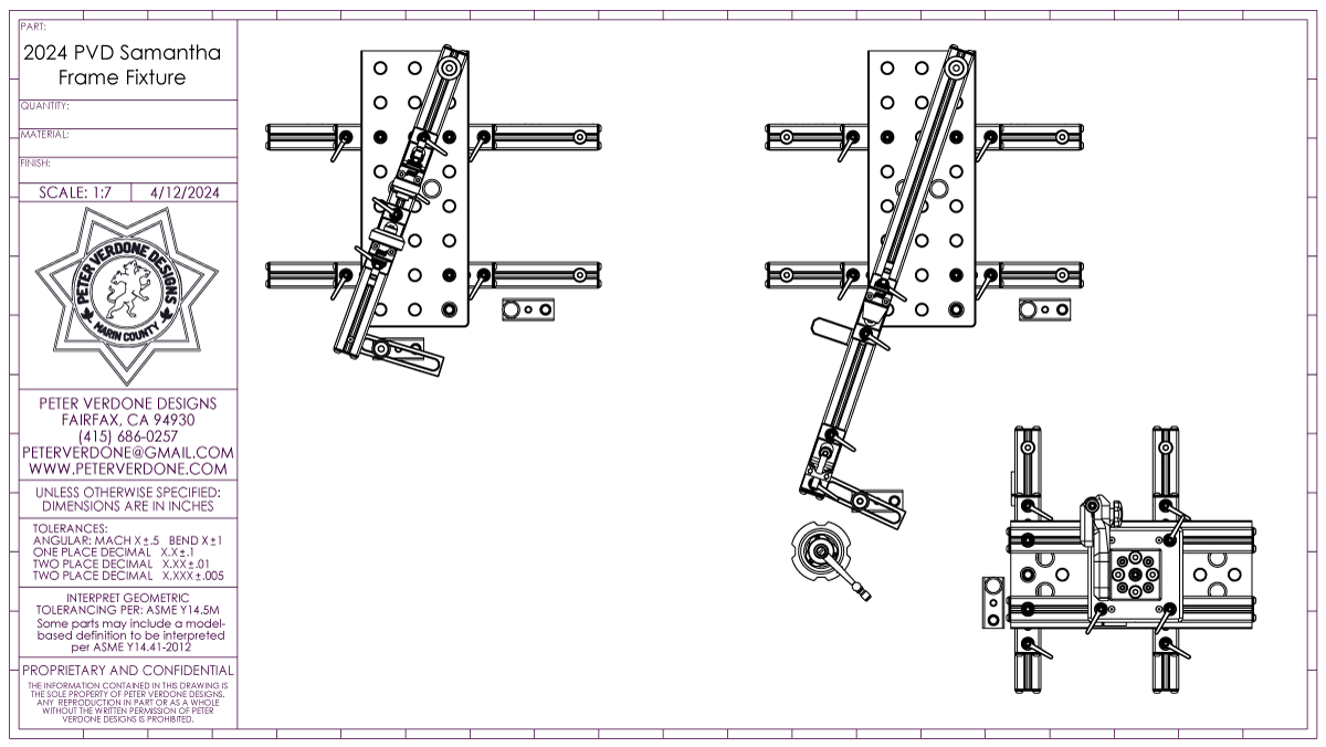
It started as a quick upgrade to the Cyberdyne System frame fixture, back in November 2023. Snowballs snowball and the ‘quick upgrade’ became the fully re-designed fixture shown here. This project has been moving forward in plain sight, with some interim posts and videos for the last six months, and the Samantha fixture is now live.
Remember when thinking and looking at this fixture: It looks simple. It looks easy. Simplicity and ease are very, very hard and take an incredible amount of work and time to pull off.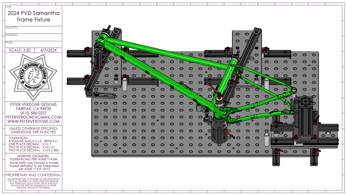
What got me here?
Not too many people in the bicycle frame building world have designed a frame fixture, let alone a truly novel one. Most folks getting into constructing bicycle frames quickly cobble something together. Barely functional, from terrible plans found somewhere online posted by questionable experts, these fixtures get hurriedly built by a novice fabricator desperate to get to building their first bike frame. They know little of bicycle design, bike geometry, machining, or tool making. We see these all day long. Worse, the fixture will be used once or for decades without improvements and without considering their limitations.
There are decent fixtures for sale. Many folks have purchased these. A wad of cash produces a good enough tool, arriving in the mail in a few short weeks. I bought a couple of Anvil fixtures from Don Ferris early on. I wanted to make bikes, not tools. Jeff and Joe sell their fixtures to folks. For most, this is a wise start and I understand wanting an off-the shelf solution.
After constructing the Supermarine Spitfire (late 2019), I had found that my frame designs had moved past what the Anvil Journeyman was capable of. Front ends had grown radically and I was at the pointy end of the curve. I began planning a way to build a new fixture that would allow me to build I wanted, without limitation.
[Deep background: I made a frame fixture in the early 1990s. Jeff and the rest of the Independent Fabrications crew were working out of a converted church building in Dorchester, renamed Nexus. It was very rough office, workshop, and industrial space. A fireworks producer had a huge chunk of the space. There was a machine shop in the basement where you could pay to play. I figured that I’d buy some time to work on my own project. It didn’t turn out very well, and even if I had photos of it, might not post them. It was a bad design built by a guy who knew little about making tools and less about bikes. Still, I had dreams and I cut metal. It rusted away, never producing anything but false starts. I learned that there was far more to this that I understood. I would be more prepared next time.]
I was just starting to get a vision of my new frame fixture when COVID19 hit (early 2020). The world stopped, but the time fueled my project. I took that opportunity and dove hard into a month-long CAD hole. Days and weeks without interruption can produce great things. I developed the math and made models. I sent prints to a friend’s machine shop for the CNC parts and did my own turning at my shop on the empty SFSU campus. By June, I had finished the Cyberdyne System.
The Cyberdyne was a brand new approach: an extremely precise, adjustable bicycle frame fixture designed for use on optical breadboard or fixturable welding table. The raster made obvious laying out complex kinematic suspension systems in real space. It was beautiful and gave me a whole different perspective on what kind of tooling we need.
This is the fixture that I’ve been using for the last 4 years. It’s been enlightening to explore what I can do with it and what it needs for improvement. I’ll get to the criticisms of the design in a few paragraphs.
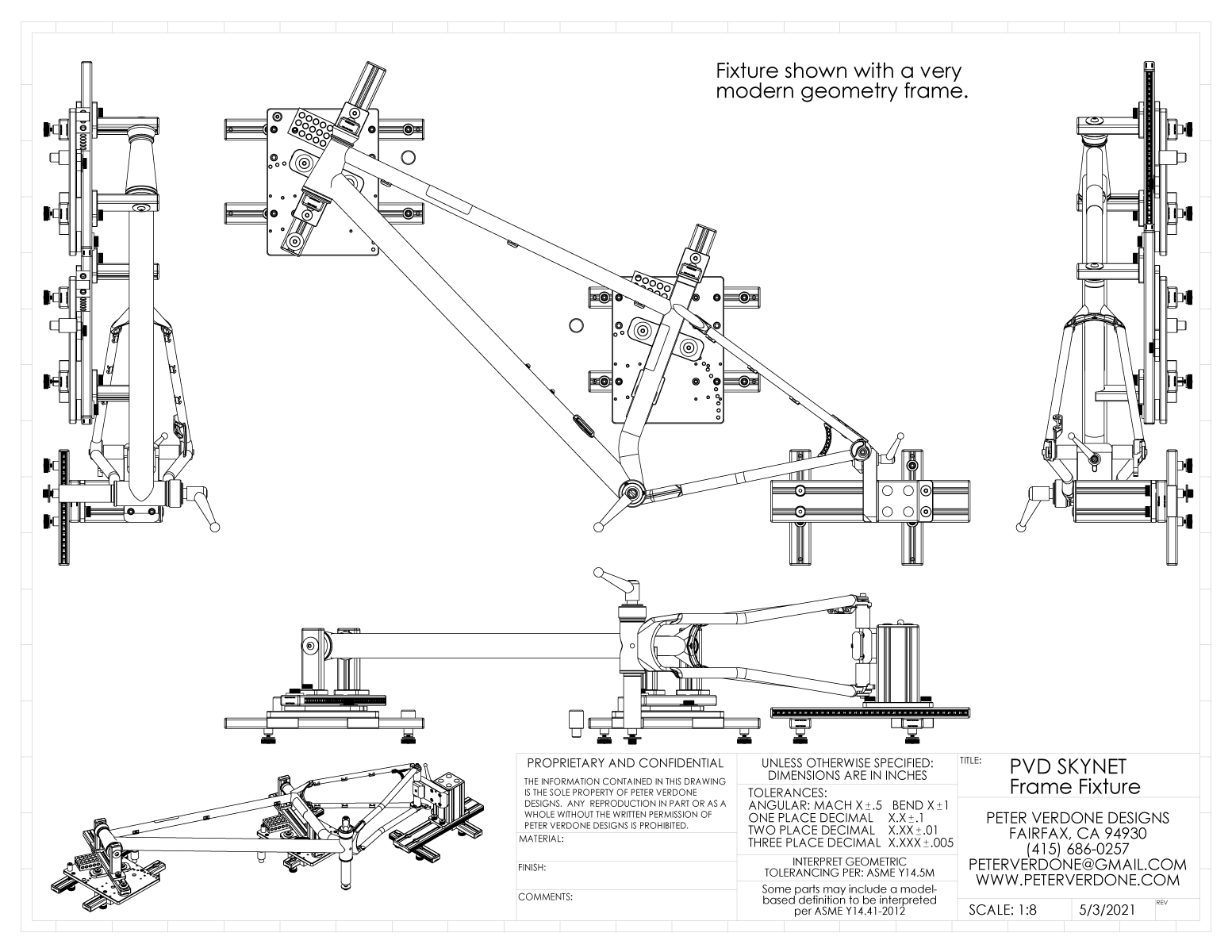
Since the Cyberdyne is such an expensive and challenging fixture to produce, and I knew that others could benefit from a cheaper and easier to make version, I designed the SKYNET fixture and published detailed plans to make it to my website. Anyone can and did make use of this opportunity. Engineering this design enlightened me, exposing some new and better ways to look at the problem.
A bit later, after I came to another level of understanding for how we can use the raster surface in design, I conceived a maximally stripped down fixture, the WOPR, which I again designed and published detailed plans. While I love this fixture, it isn’t adjustable in the way I’d prefer. But like with the SKYNET, new lessons were learned.

Recently, I produced a short video series about fixtures and posted them to my YouTube channel. They are worth checking out as I talk a bit about general design and my work.
I’ve also worked on other tooling that works in this ecosystem. I did some handlebar fixturing on the table and mill. And created a wheel tool that does much more than any others that I’ve seen. Ongoing work with the system showed me solutions that I hadn’t seen four years ago.
So, depending on how you choose to count, I’ve designed four (five including the shitty one) different frame fixtures and built three, plus some compatible tools. This is a foundation that others don’t have.
Originally, I hadn’t planned on building a whole new fixture. Cyberdyne is a great fixture that works well. I just wanted to update the fixture addressing one of the main issues (#1 below). But then I had some ideas that deserved documentation. More ideas pulled me in further. Then it seemed too good of a design to not realize. The snowball effect.
The main problems with Cyberdyne:
- The tube beams use a threaded raster slot pattern for clamping the cones in the correct location. This is a pain to use when doing fine tube fitting and prototype work. A sliding rail or t-slot is required.
- The horizontal slide clamps for the head and seat systems are again rastered slots and are a pain to use, especially when the angle needs to move to get at clamping screws. This needs to be on a t-slot or sliding rail.
- Adjustments with screw removal is an absolute pain compared to loosening levers and slides.
- The system uses many separate parts that need to be placed on the table correctly for use. It takes some time and attention to get things set.
- The 140mm center plane of the Cyberdyne is quite low and makes welding a challenge. That needs to be increased. And it needs to be easier to modify to future conditions.
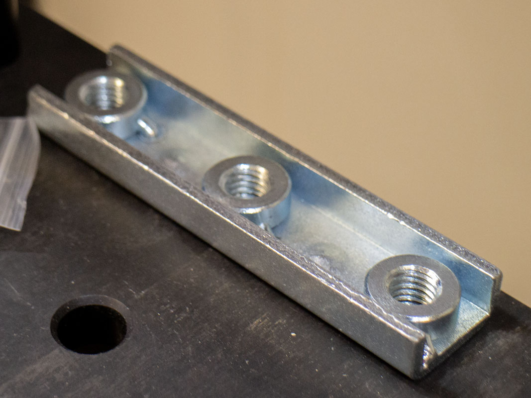
- The countersunk nuts that are used for connecting the tool to the table enter from the bottom and difficult to place quickly or remove without dropping, etc.
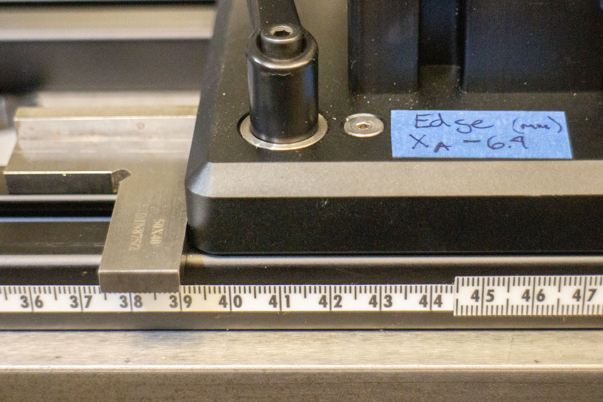
- The method of measuring component locations on the table was not stellar and needed simplification and confirmation options.
- Calibration of the crank shell and axle towers is fussy and difficult to do. That wasn’t included in the initial design which was a mistake. New designs are needed.
- The crank shell pillar needs improvements to handle the loads of frame alignment.
- The tube cone system was not great and relied on Chop Source cones which was a mistake.
- The plumbing for the purge was overly complex and I hate NPT.
- Much of the Cyberdyne components cannot be used in other setups. The value built into the fixture is restricted to just bicycle frame construction.
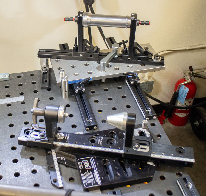
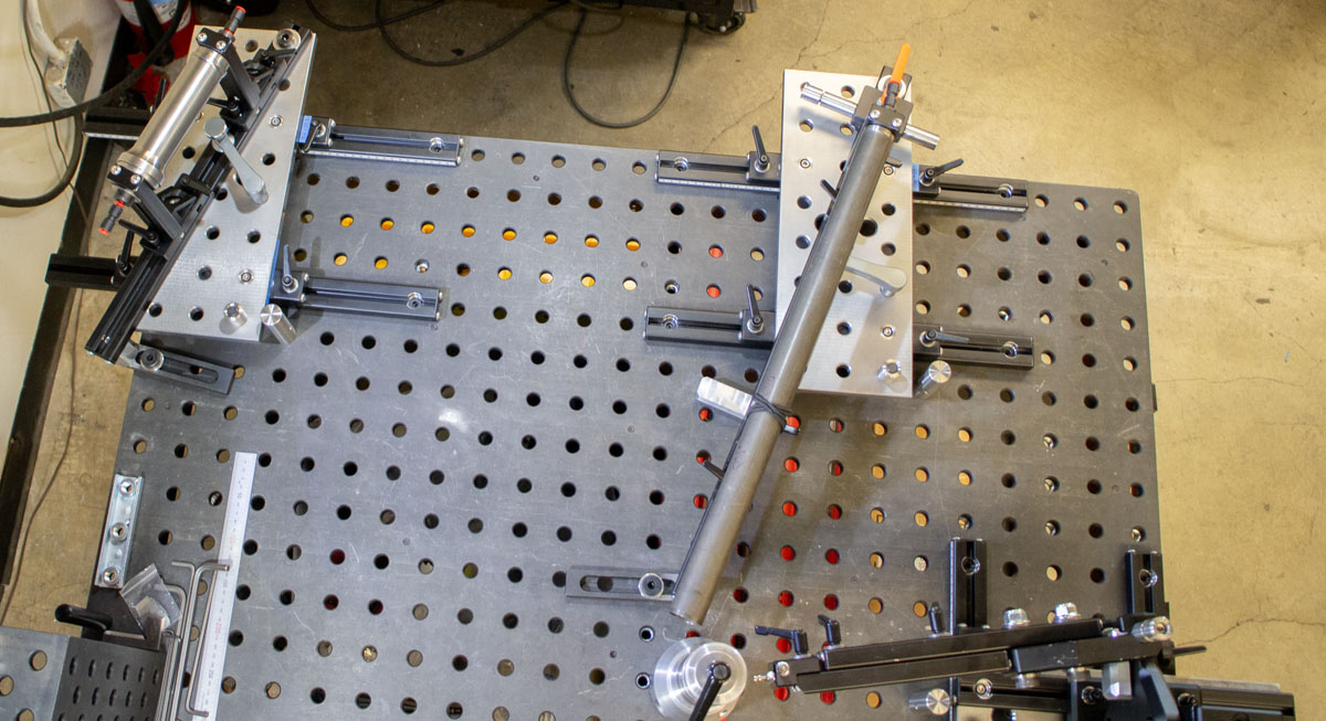
Taking everything that I’ve learned over the past four years (and more) using these types of tables to solve all kinds of problems, both in the shop and for bicycle construction, I began with a clean slate to look at the problem. Minimizing custom machining and maximizing BuildPro and 8020 materials in the design is emphasized. I spent a massive amount of time simplifying and improving the new system. Months and months have gone into it. Then, I slowly built it out, all while taking notes and making changes. What you see represents significant work.
Theoretically, much of the new design could be used in new and different configurations for many different projects. I want Legos for the shop. This isn’t a discount fixture like the SKYNET but I wanted the dollars that are spent to turn into value through the years. Steel 16mm raster universal plates were an investment but these have proven handy in the welding and machining areas of a shop.
Since this all started by trying to change the rail system on the Cyberdyne, I initially tried to get some fancy dynamic linear rail to function. There are several nice types of bearing rail out there. I found some SGR20 rail with locking 5 bearing carriages. Although this rail was really cool, it didn’t make sense in the context of this design. I was stumped, and began looking for a better option.
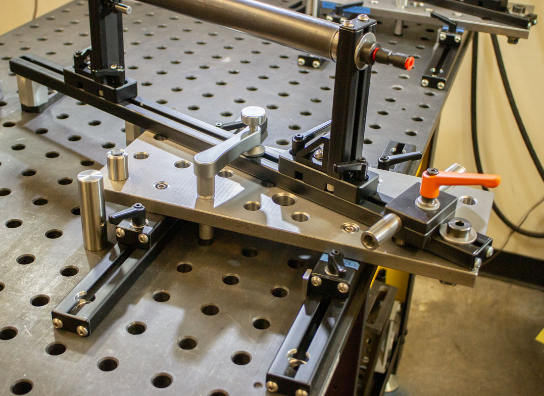
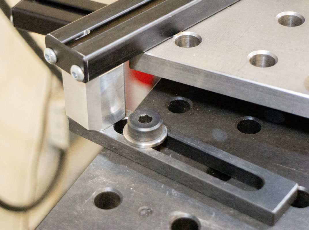
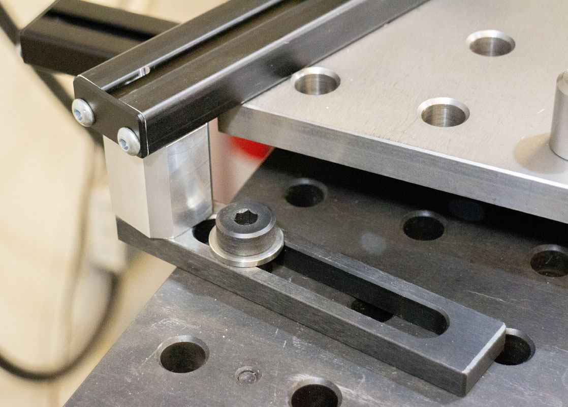
Going back to basics, I figured out a way to use 8020 1575 rail but it was overly complex and took up a lot of space. I kept at it, finally coming up with a neat and efficient way of precise positioning and locking on the 8020. The design really came to life after that.
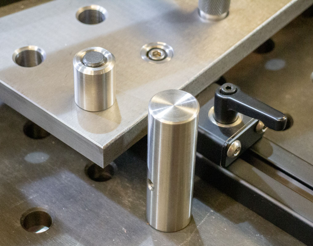
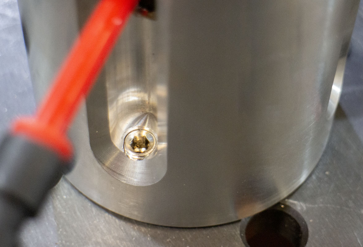
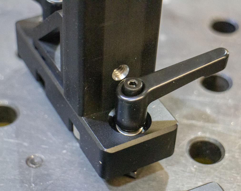
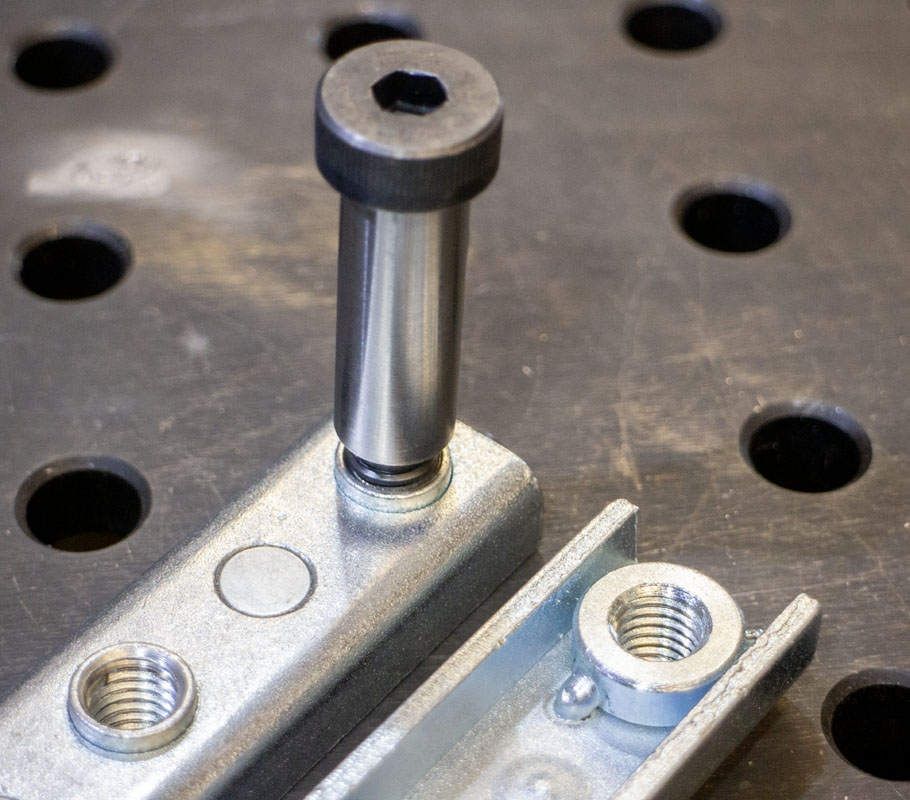
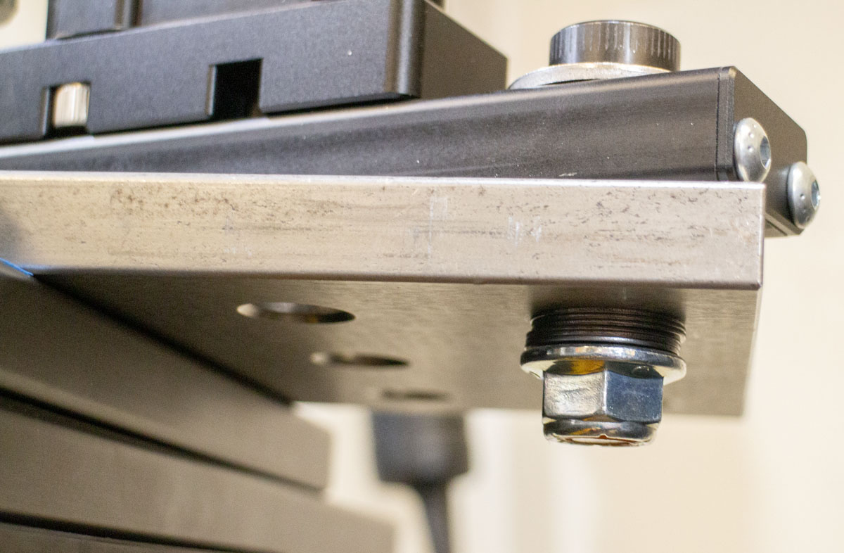
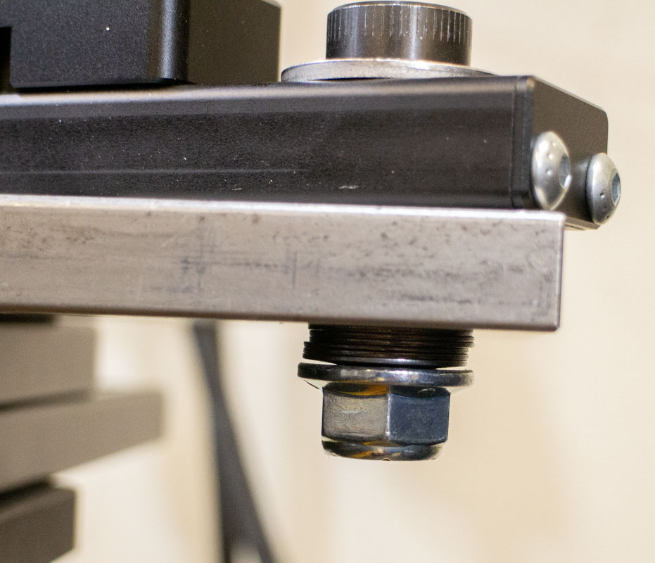
The key to accomplishing the functionality in this tool is the ample use of shoulder bolts, countersunk shoulder bolts, and some simple custom countersunk pins. Machining fairly precise holes for the 5/8″ diameters in 8020 is easily accomplished with a machine fed 0.625″ endmill and a 0.750″ 90° chamfer mill. Fitment can be ensured with stainless shim stock.
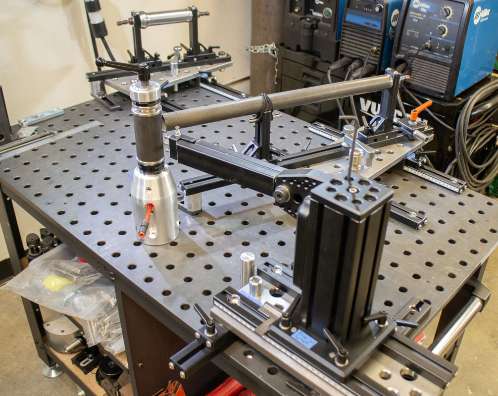
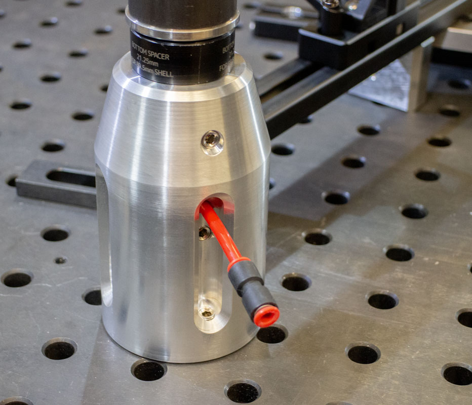
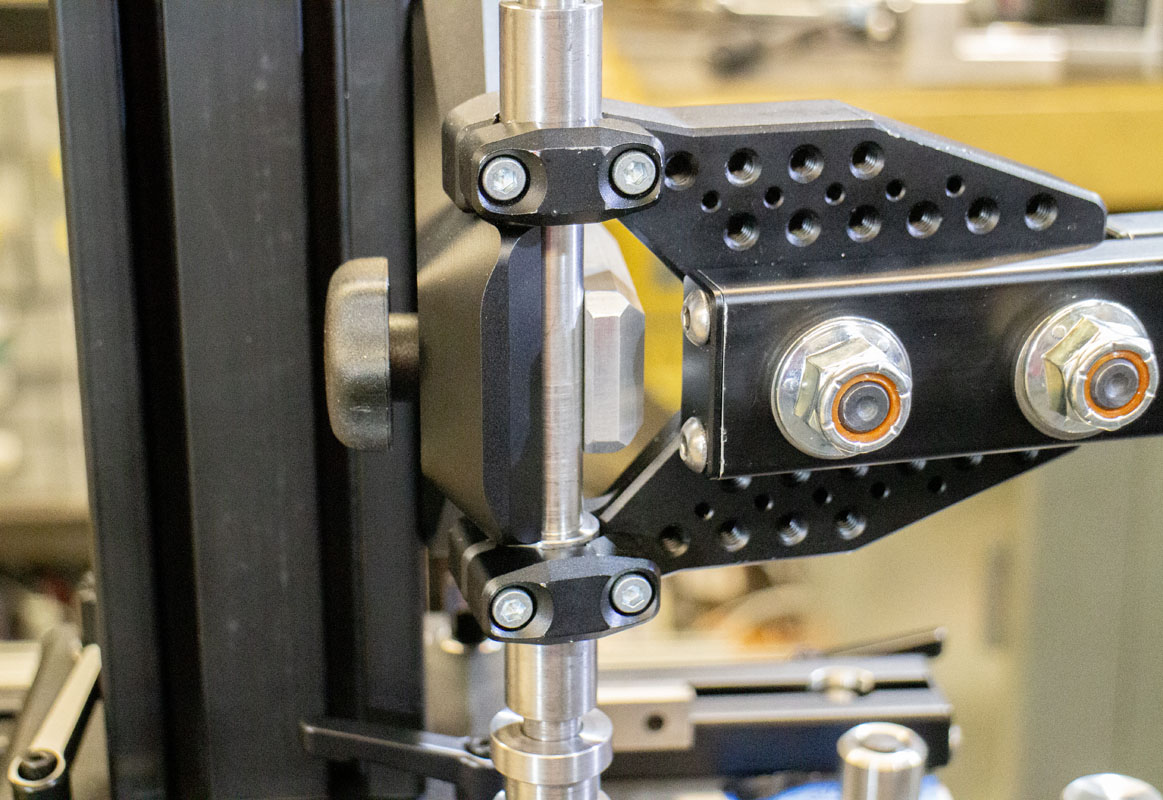
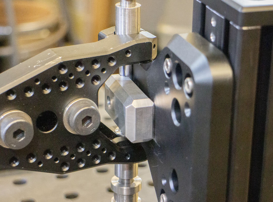
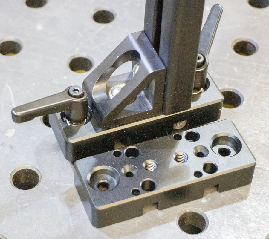
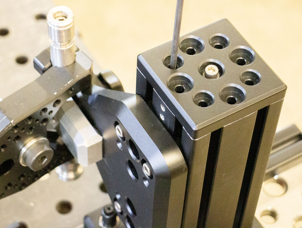
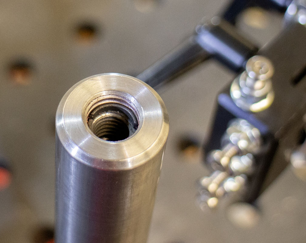
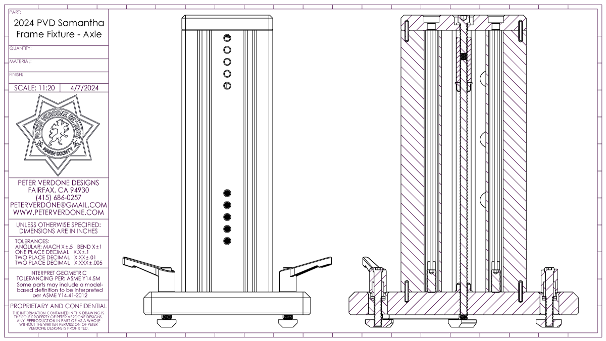
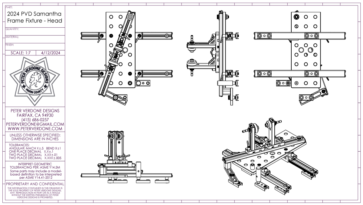
I’m especially proud of the calibration system for the axle tower and the attachment of the crank shell pillar. Even the slightest misalignment of these elements has significant effect on how the wheel and crank interface with the rest of the bike. As precisely as all of the parts were machined, there’s always going to be some stack up and deviation in the assembly to account for. Calibration should be built into the fixture. Four fine threaded set-screws at the bottom of each of these subassemblies allow for very close adjustment to optimum. In both cases, four screws made more sense than using a kinematic constraining desire for three. That’s just how life is. Notice how the tension rod in the axle assembly does all of the work while the other pins and screws take care of alignment.
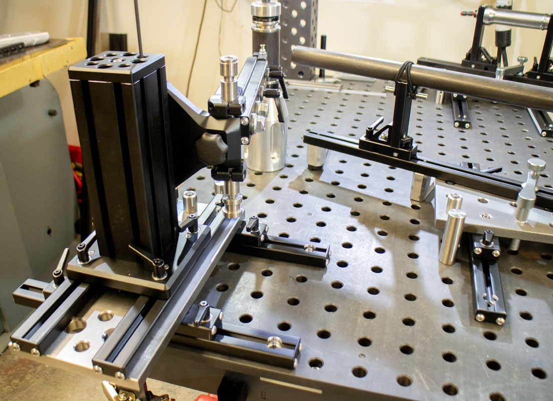
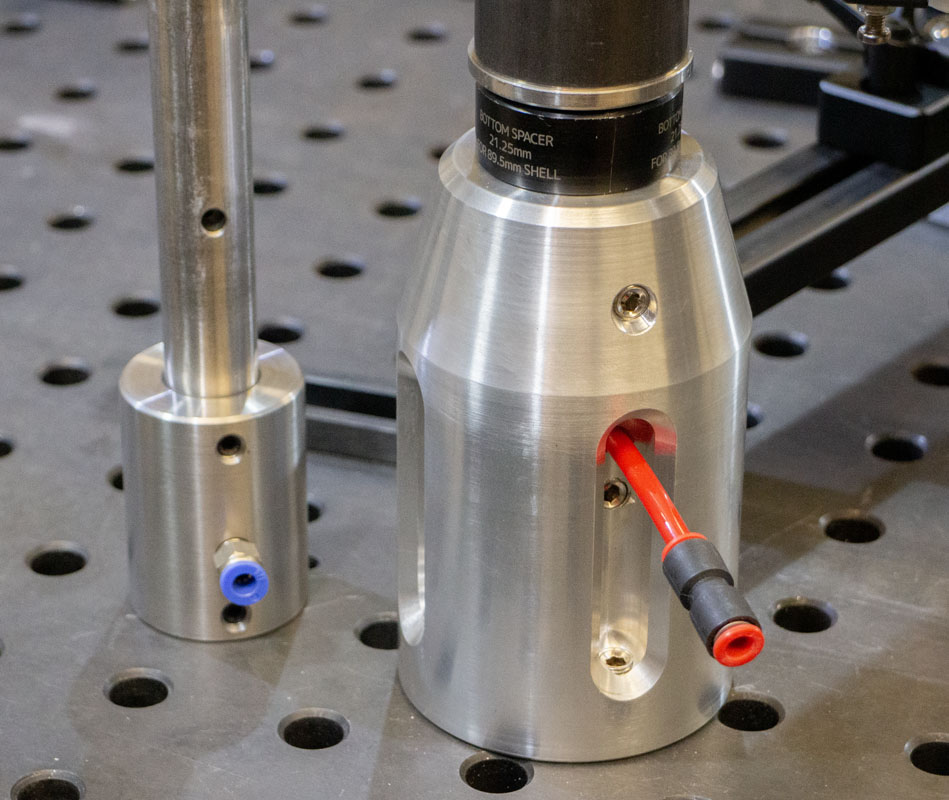
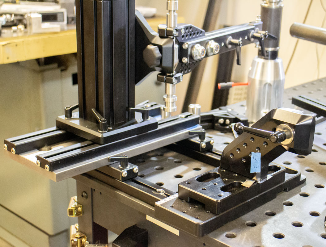
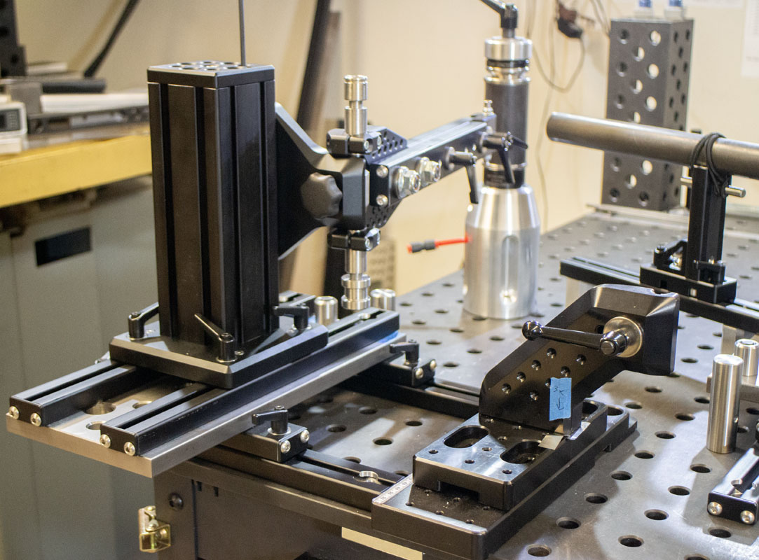
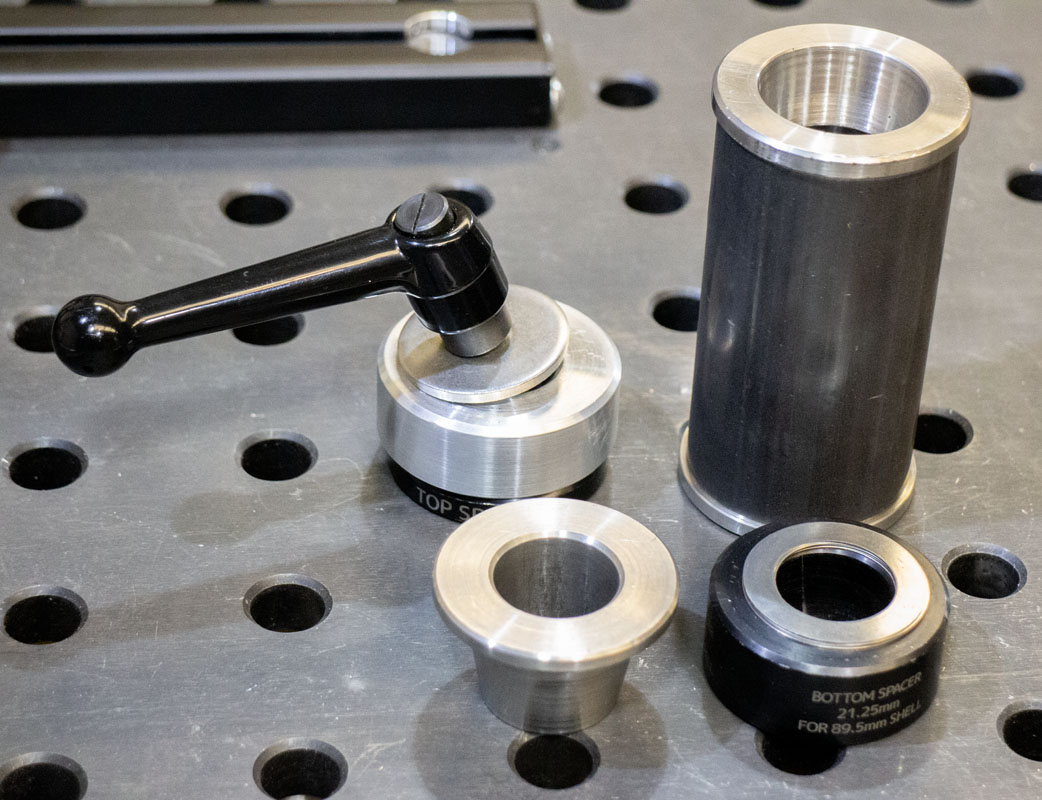
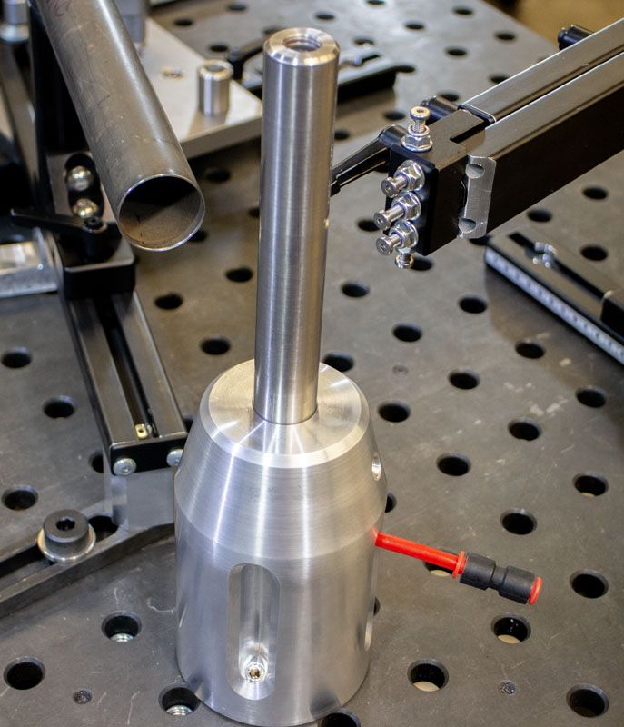
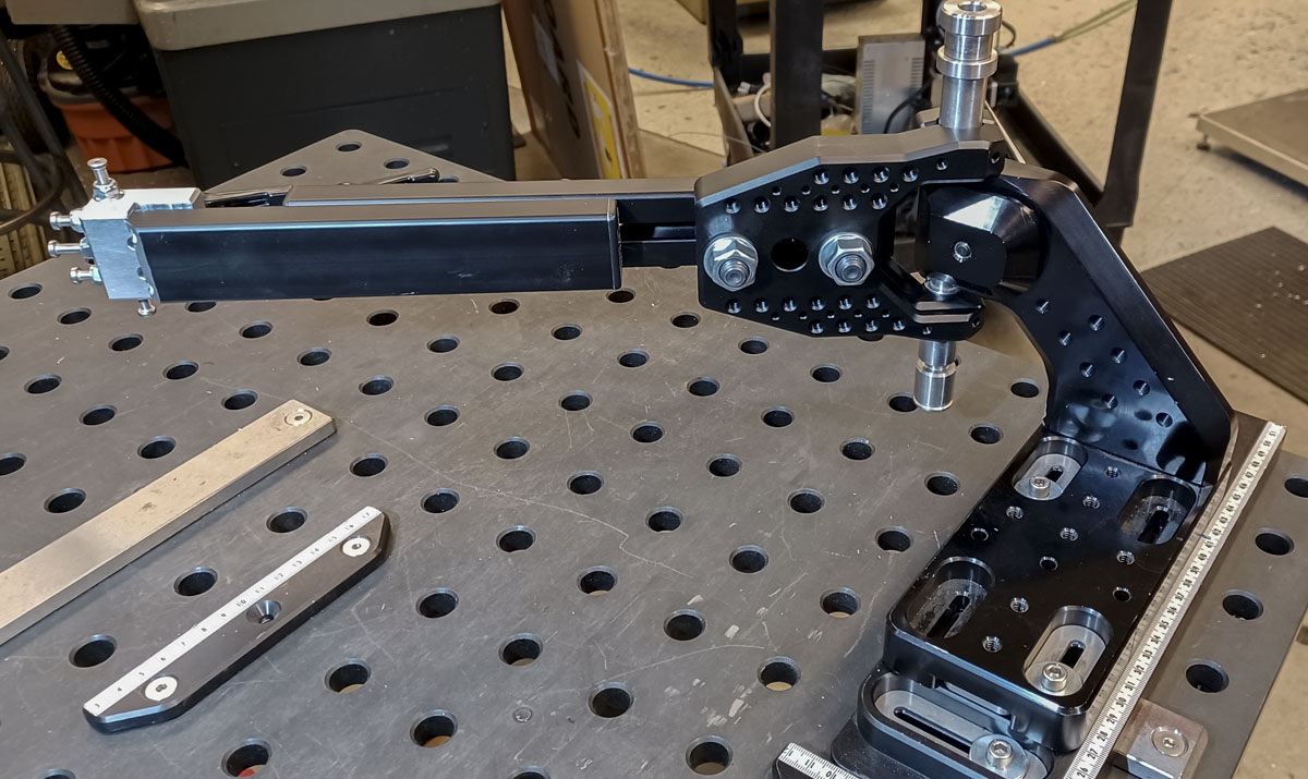
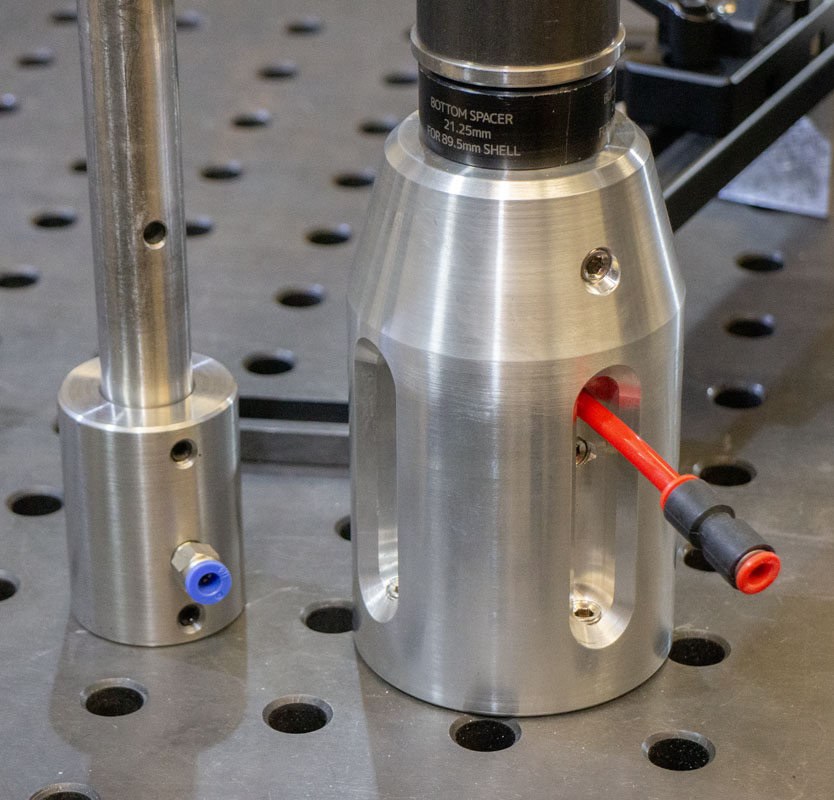
I love how rigid the crank shell tower is. A lot is going on here that makes it a brick shithouse. So much so that frames can be aligned in the fixture. Can anyone else’s fixture (outside of steel Taiwanese production tooling) handle this? Max shell width as built, 140mm.
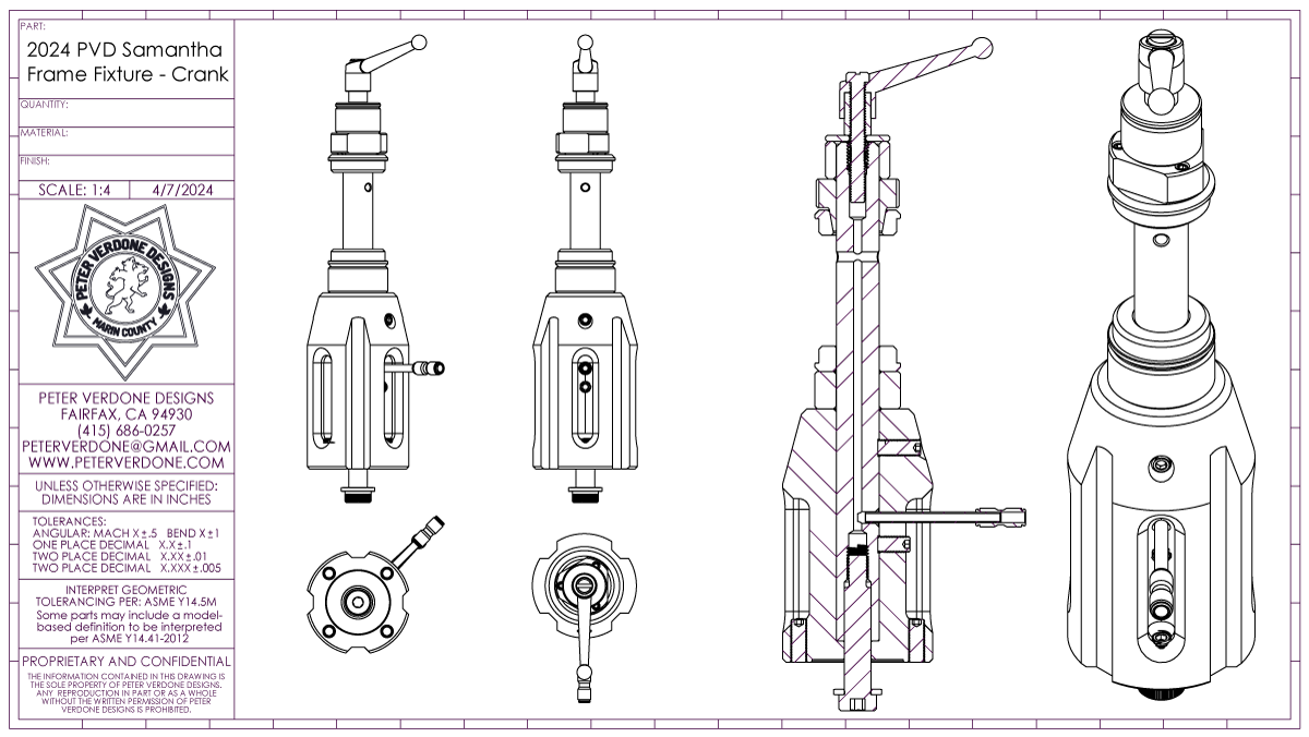
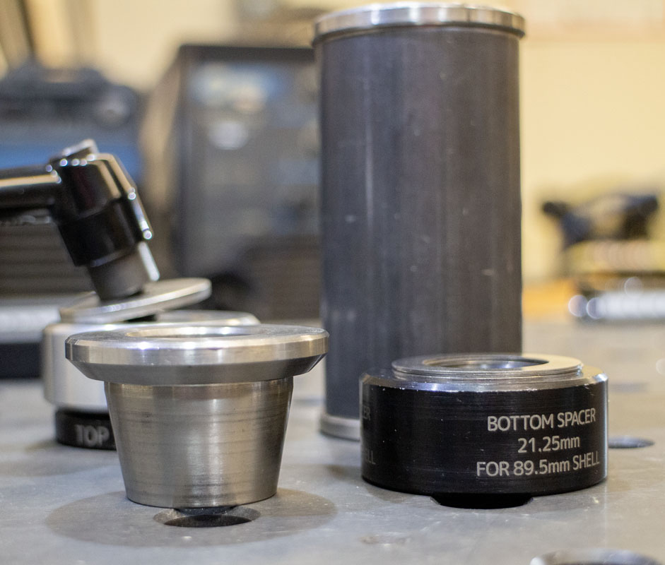
The difference in scale between the crank shell tower from the Cyberdyne and the Samantha is startling. It’s not just the change from a 140mm center plane to 220mm that gives much needed access for torches and tools. But it’s stronger. It’s calibratable. Even the way it bolts to the table, the part you can’t see, is about 100x more rigid. This is rocket science!
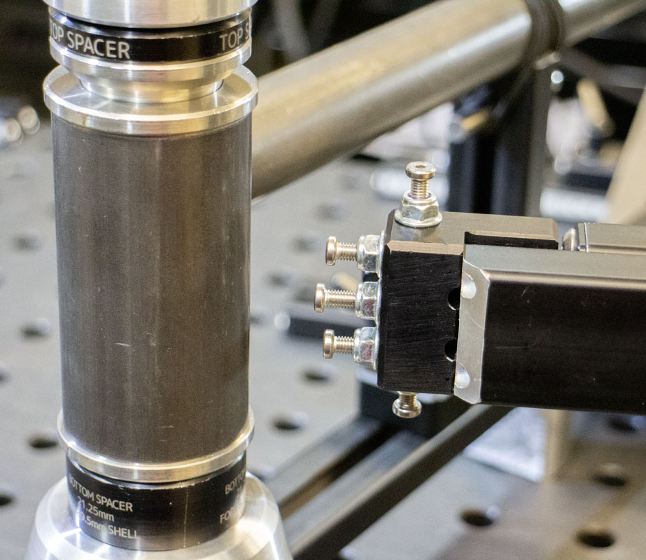
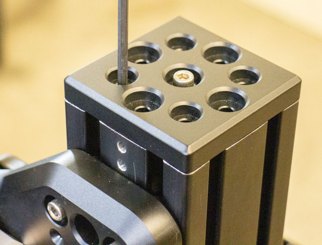
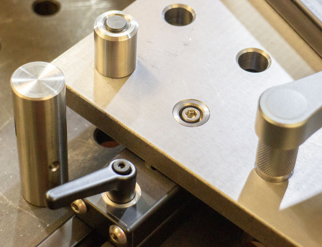
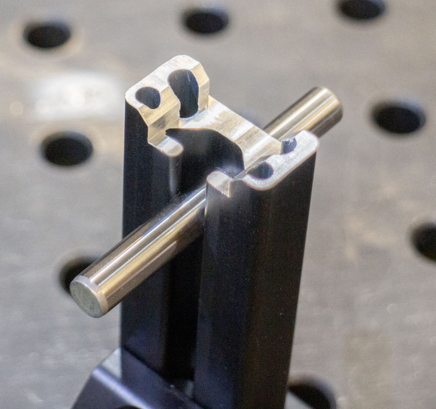
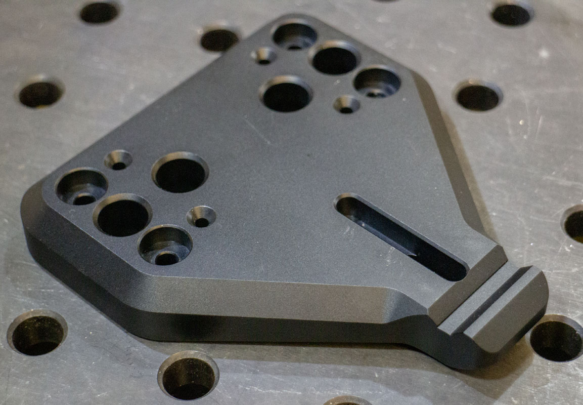
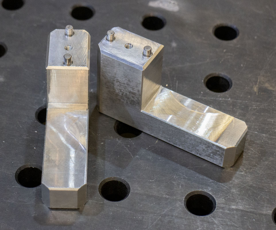
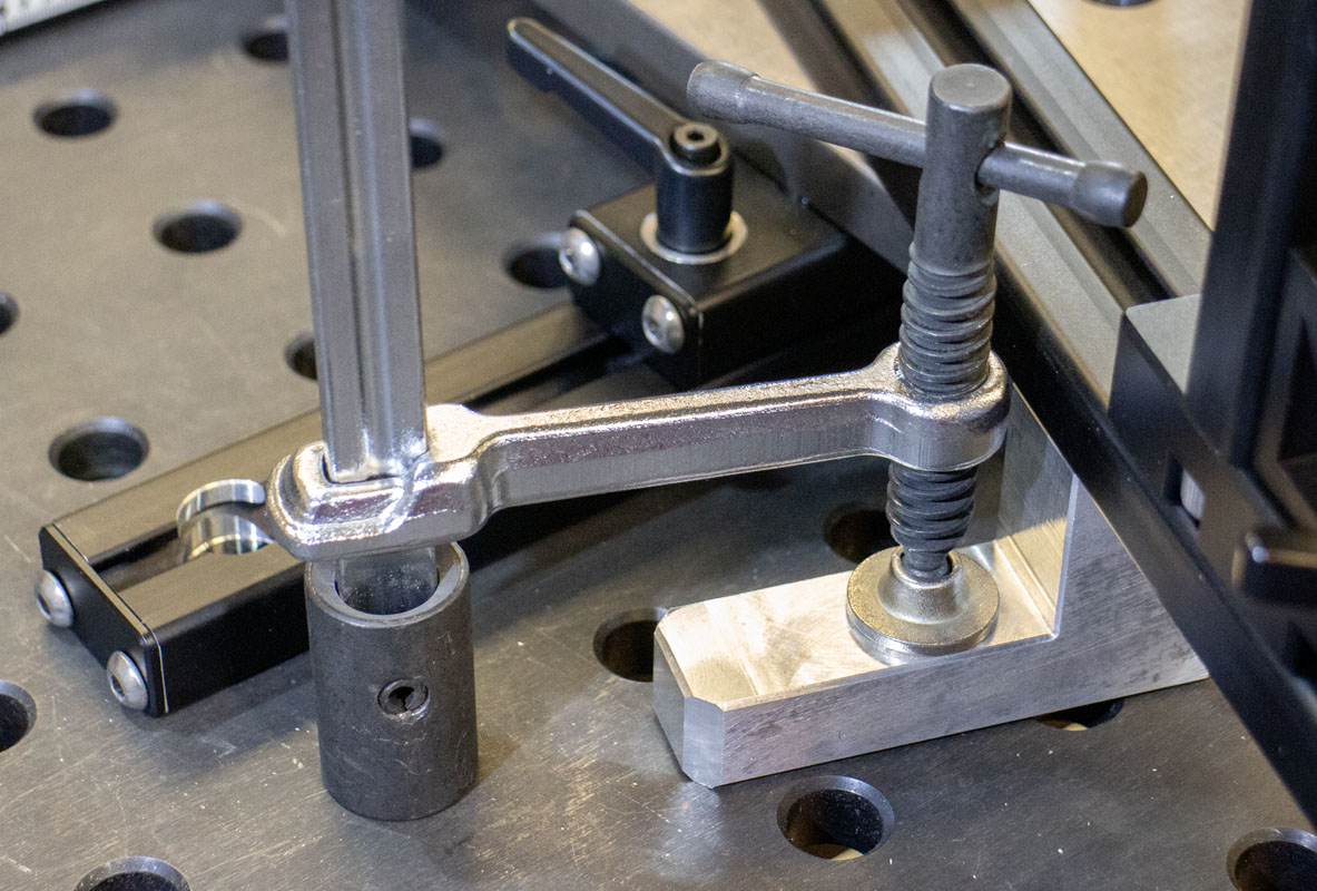
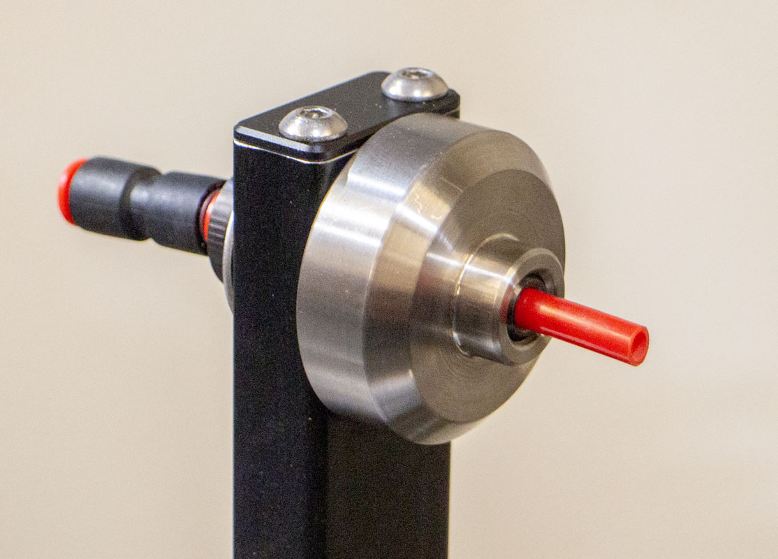
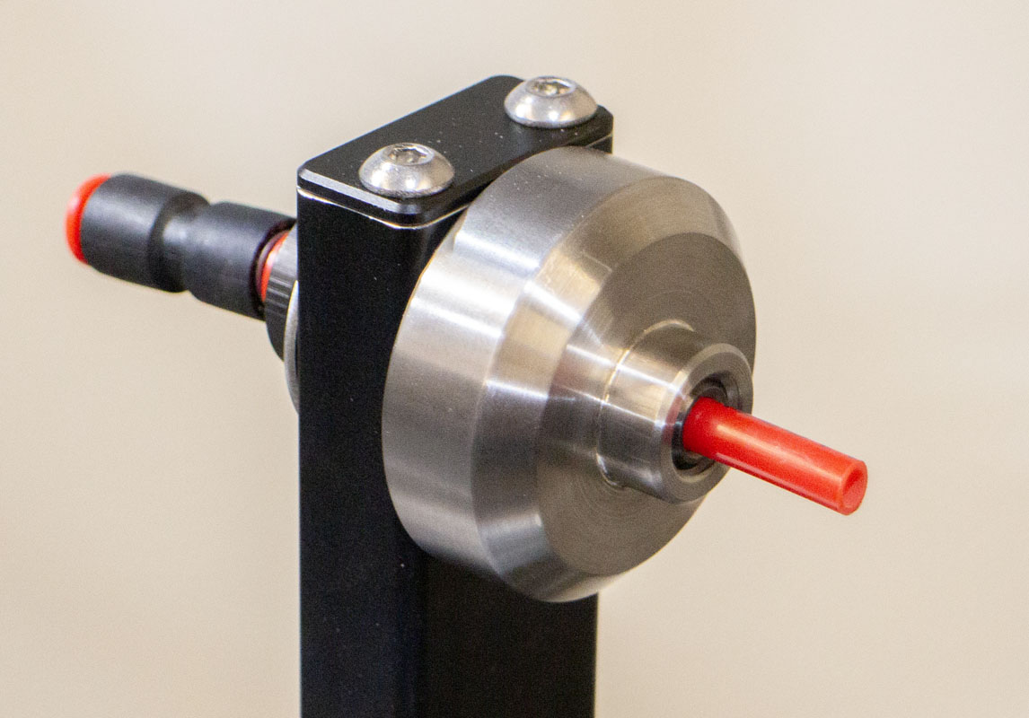
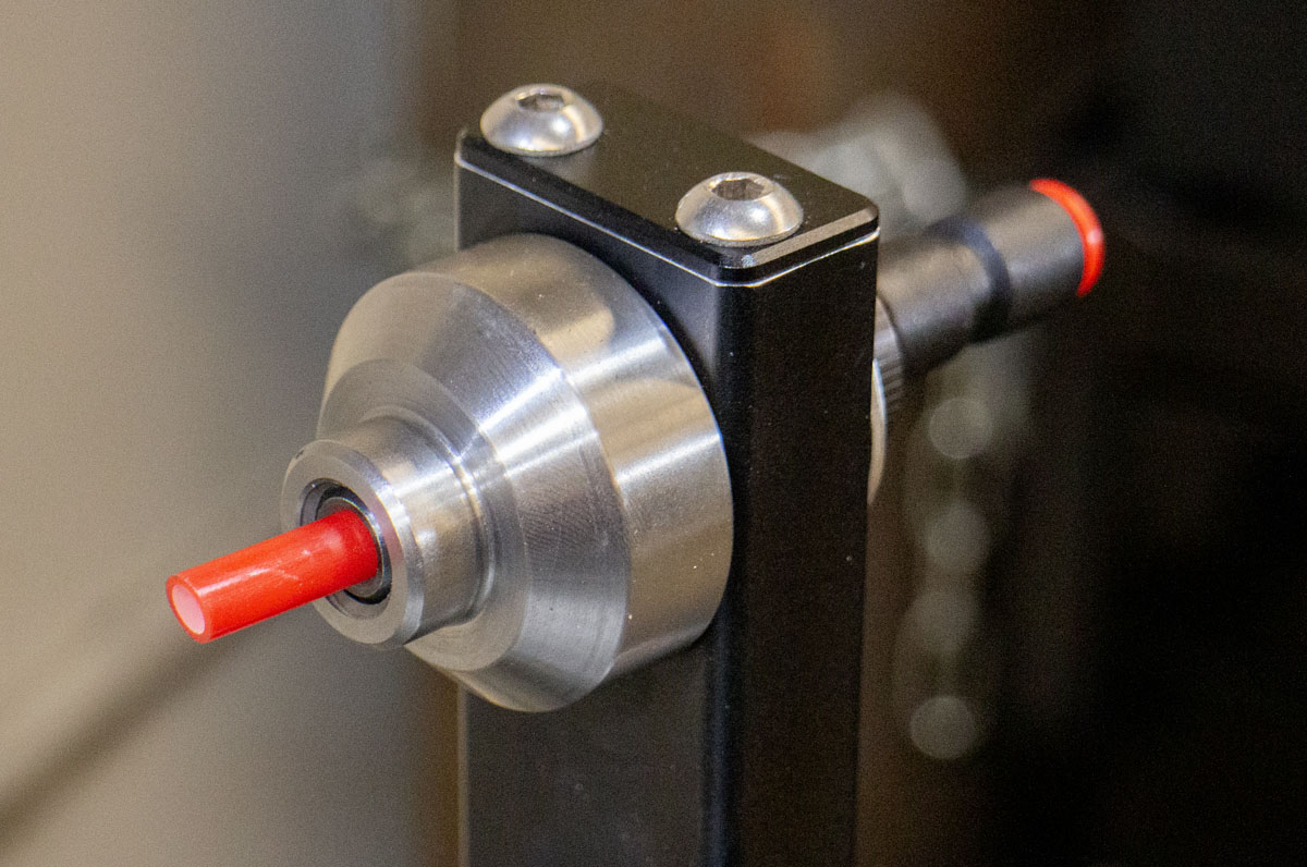
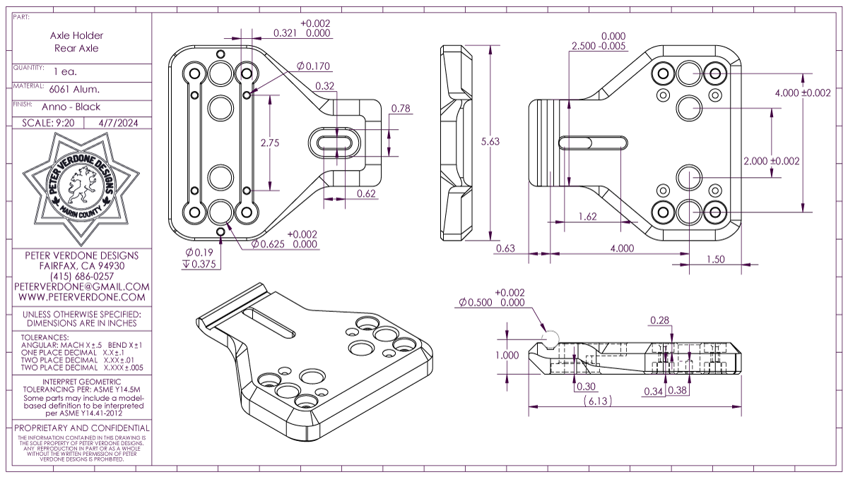
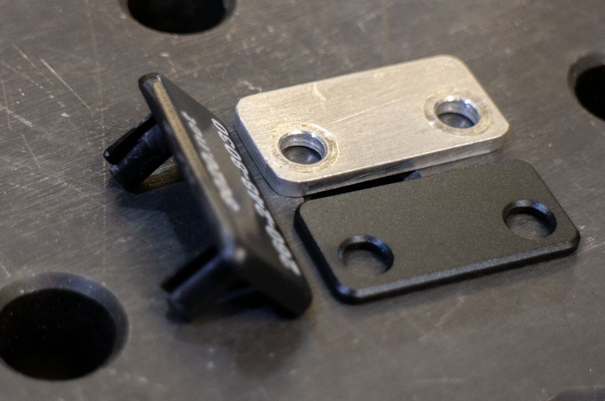
The axle holder is designed with a vee groove for kinematic repeatability. I learned my lesson on this and won’t be repeating it soon if I can help it. By adding the 4 5/8″ holes in the plate it can be mounted on or between pin rows in the fixture table. This makes tooling options for mitering and subassembly welding easy.
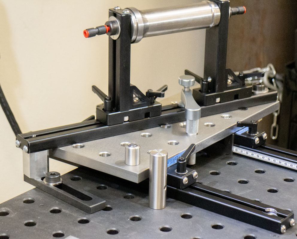
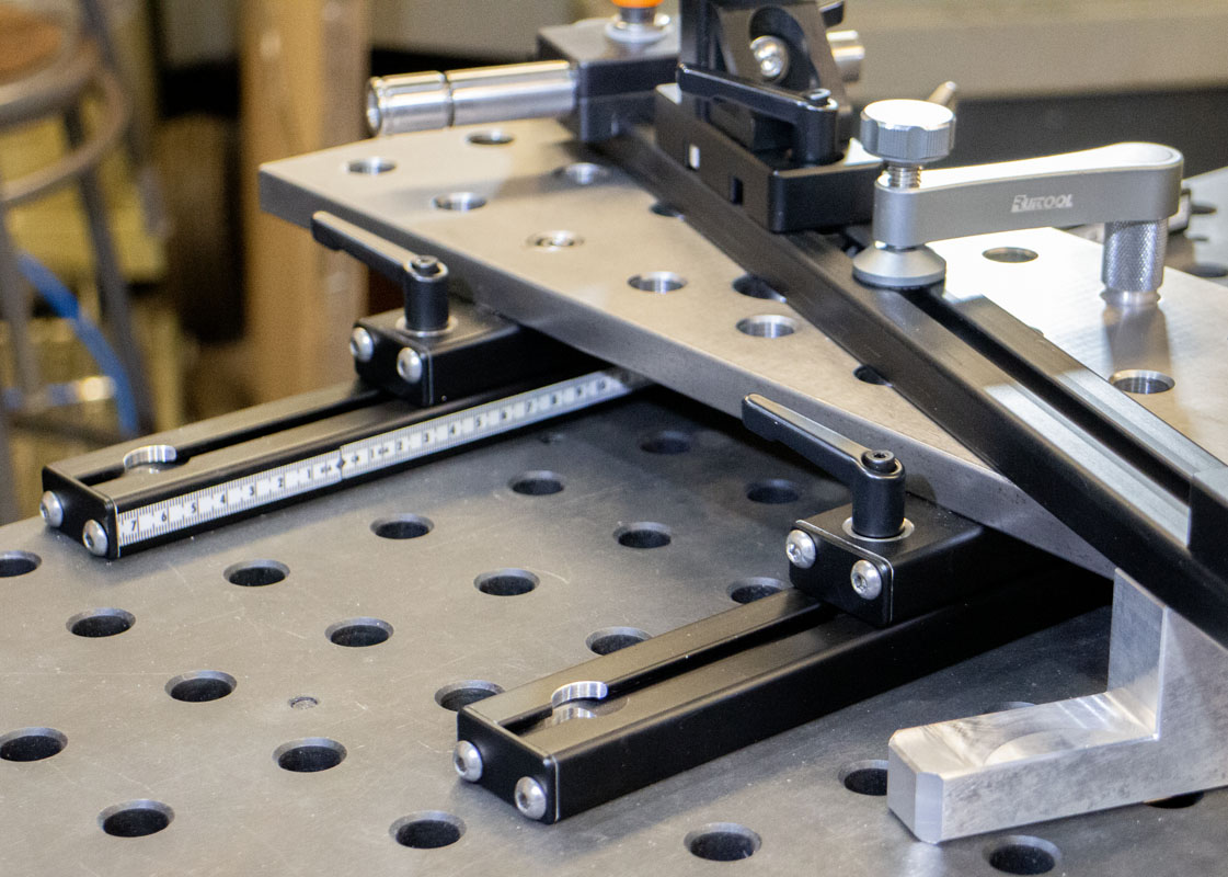
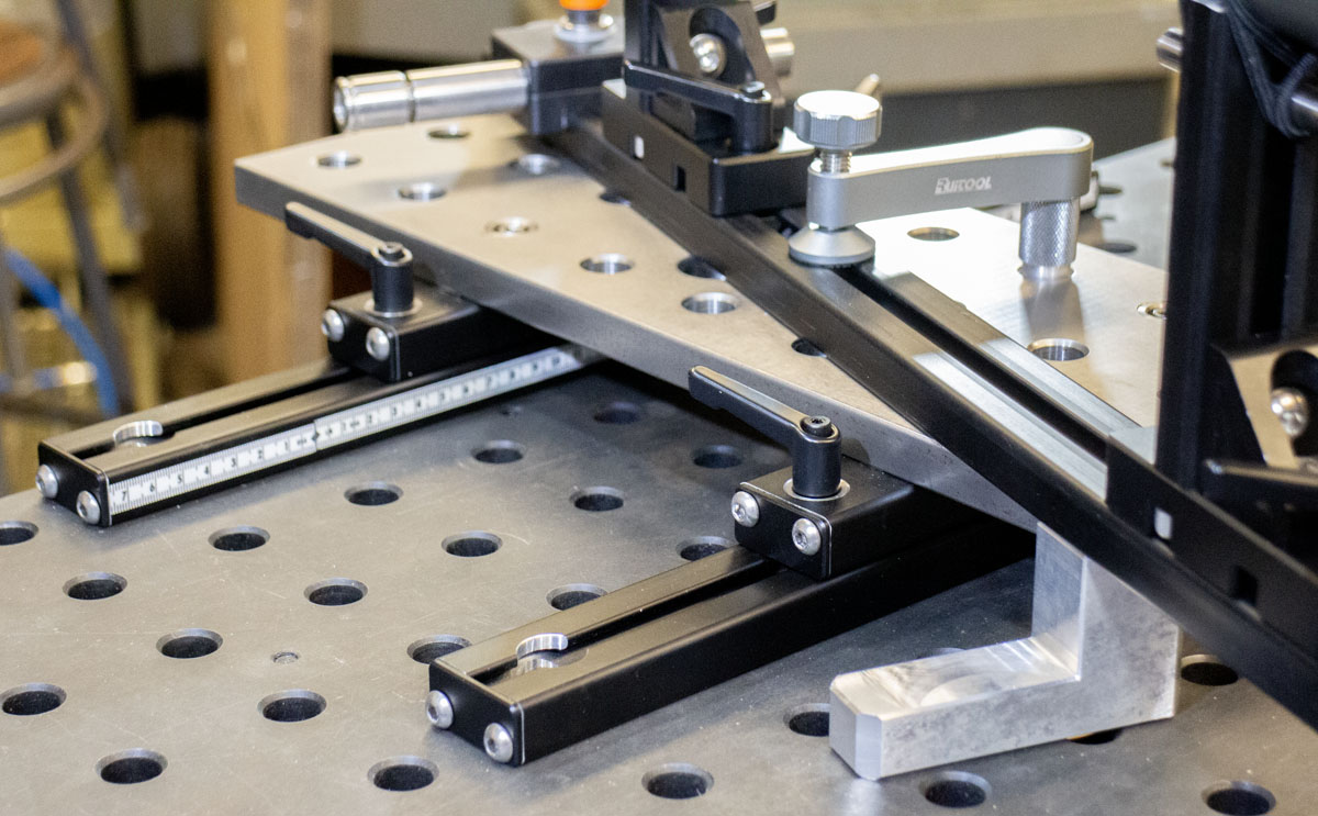
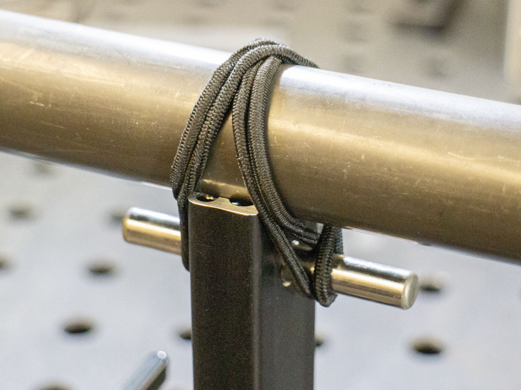
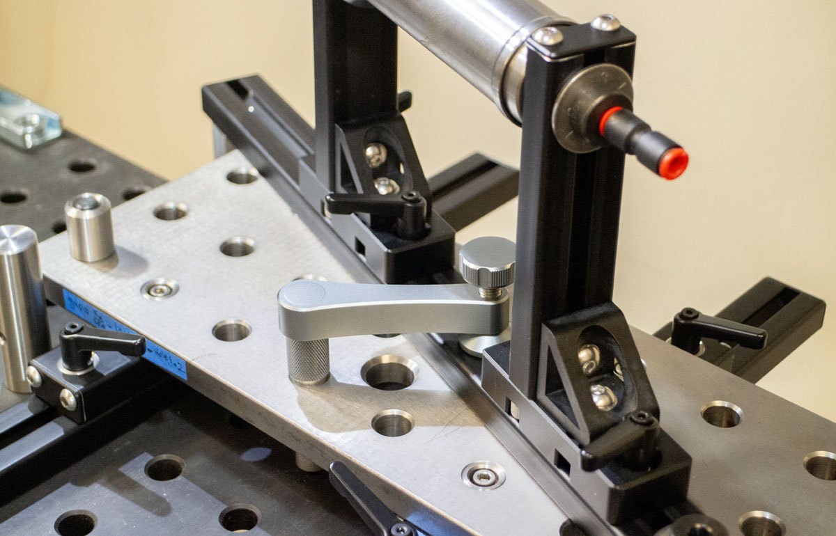
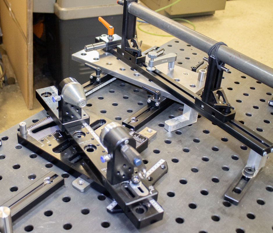
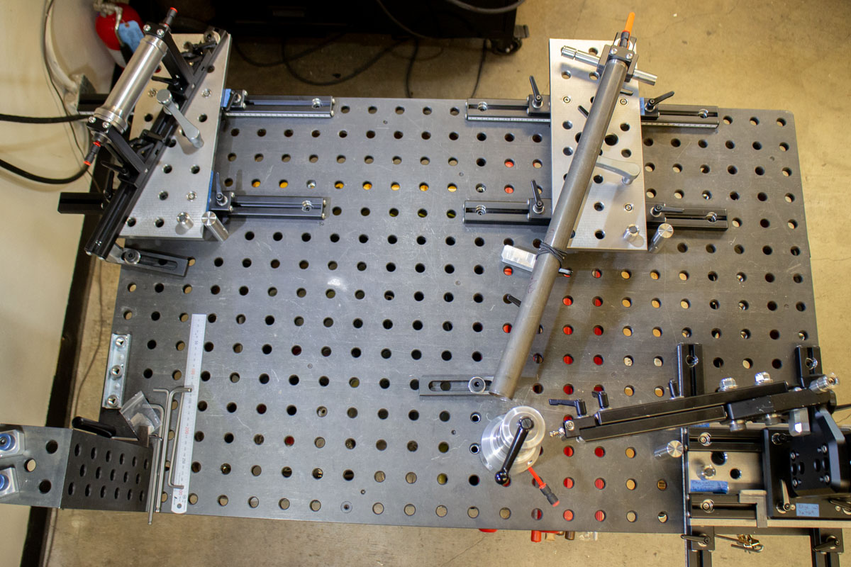
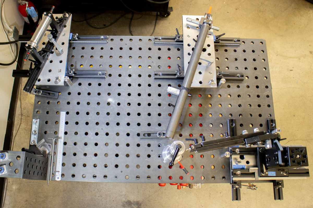
It would have been nice to go with two long rails to guide both the head and seat tube subassemblies rather than the four that I show. I had concerns over my ability to place a pin hole at the precision needed over such a long distance. As shown, I’m able to bore them in one setup using the DRO on my mill. There is a benefit to breaking these up. It’s an easy job to quickly remove and install each sub-assembly (see video). With a longer rail, the system would be more elegant, but more of a pain to set up.
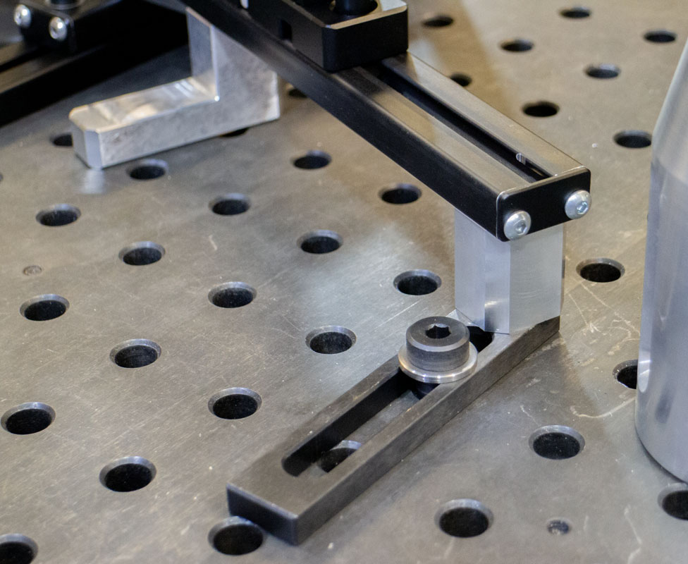
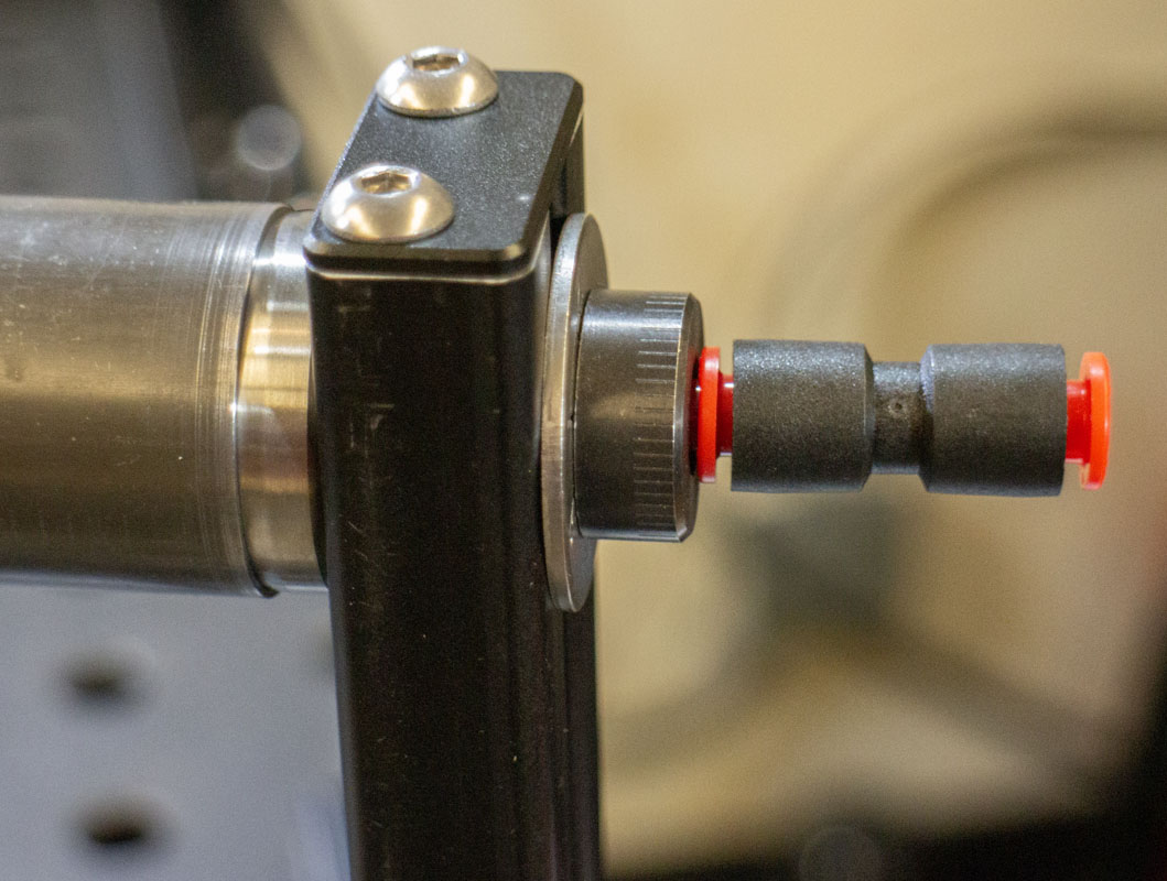
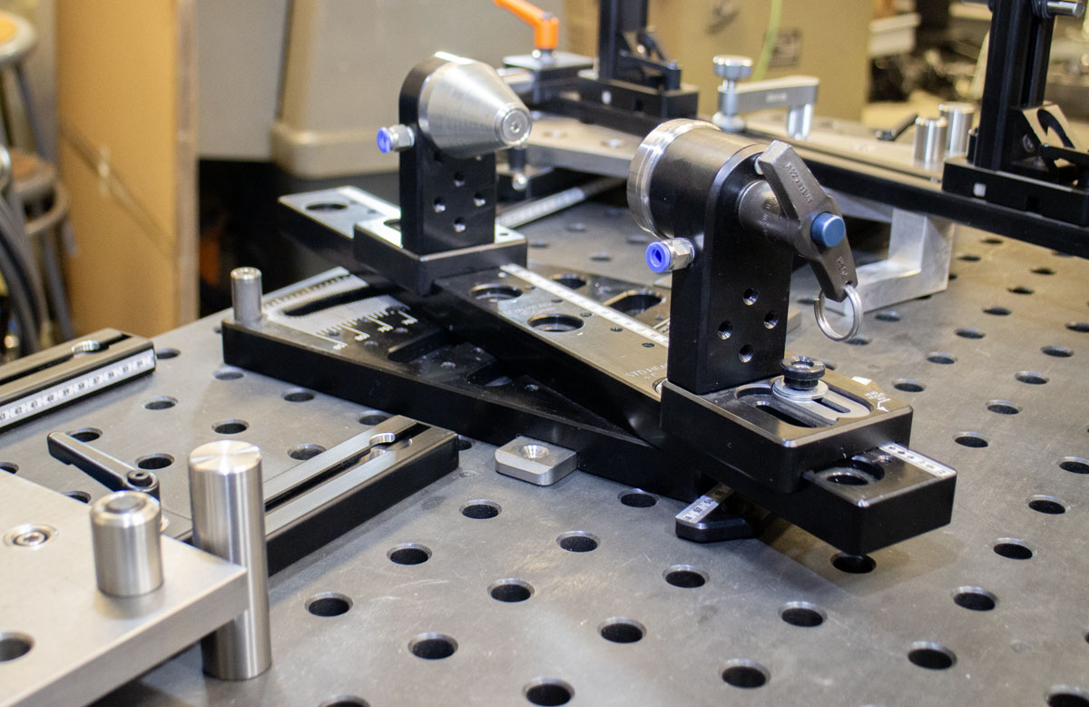
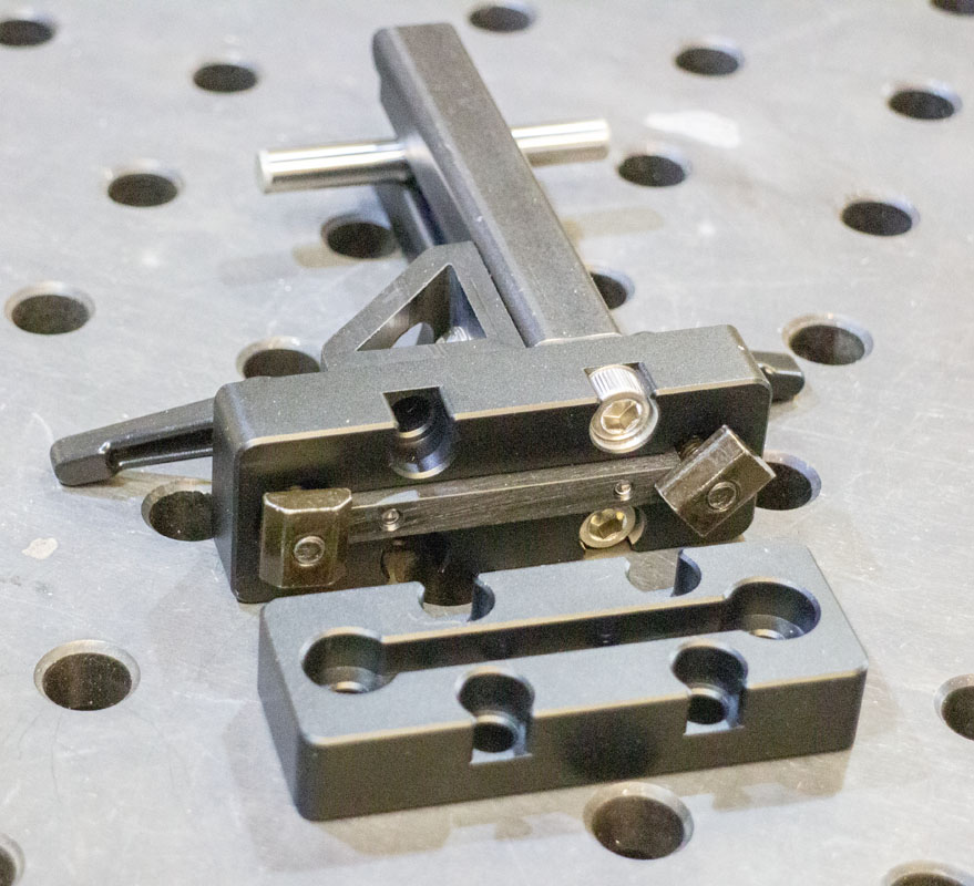
The cone mounting method is cool. It’s so simple, precise, rigid, and reconfigurable. It can mount anywhere there is a 5/8″ hole, which means anywhere in the ecosystem.
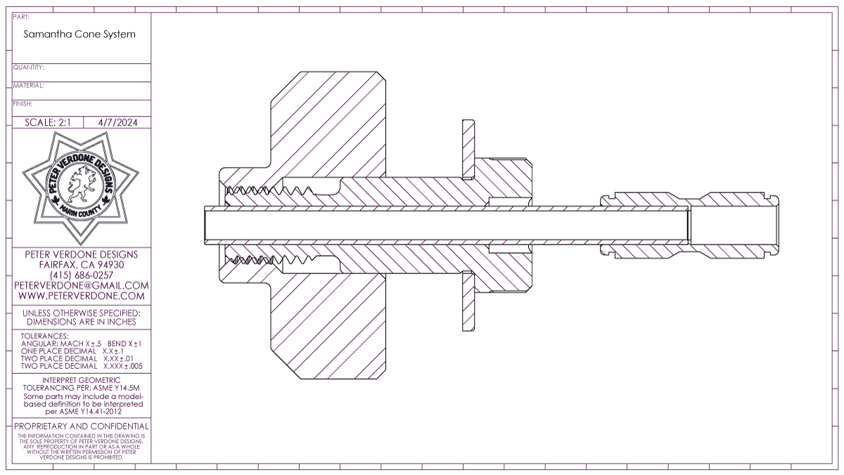
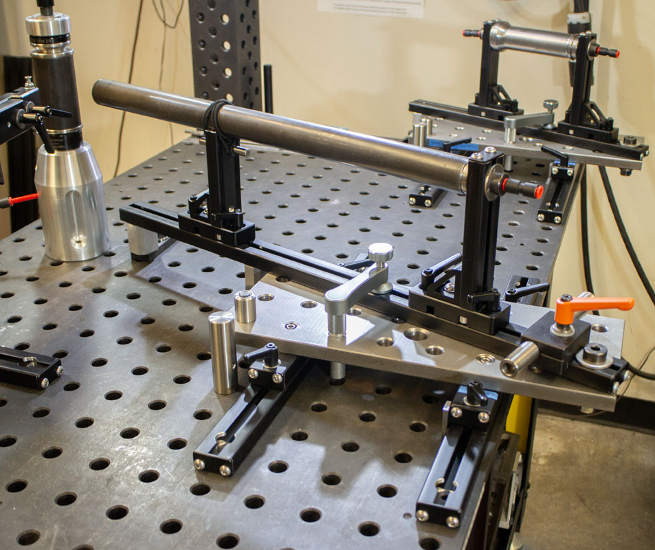
I’ve been playing with different cone profiles for optimizing the hold. A lot of ideas are circulating. A shift is much shallower cone angles to increase the hold that they have on tubes. For example, the seat tube cone for 31.6mm pin has a 20° angle and really fixes the tube well.
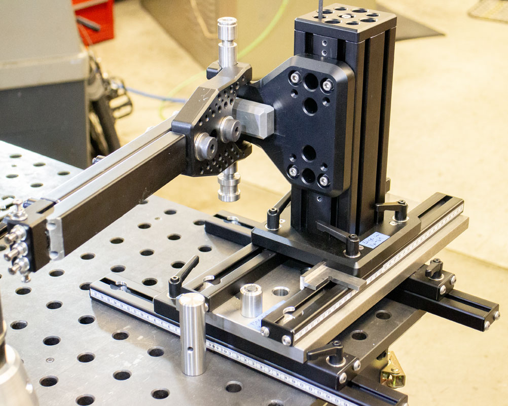
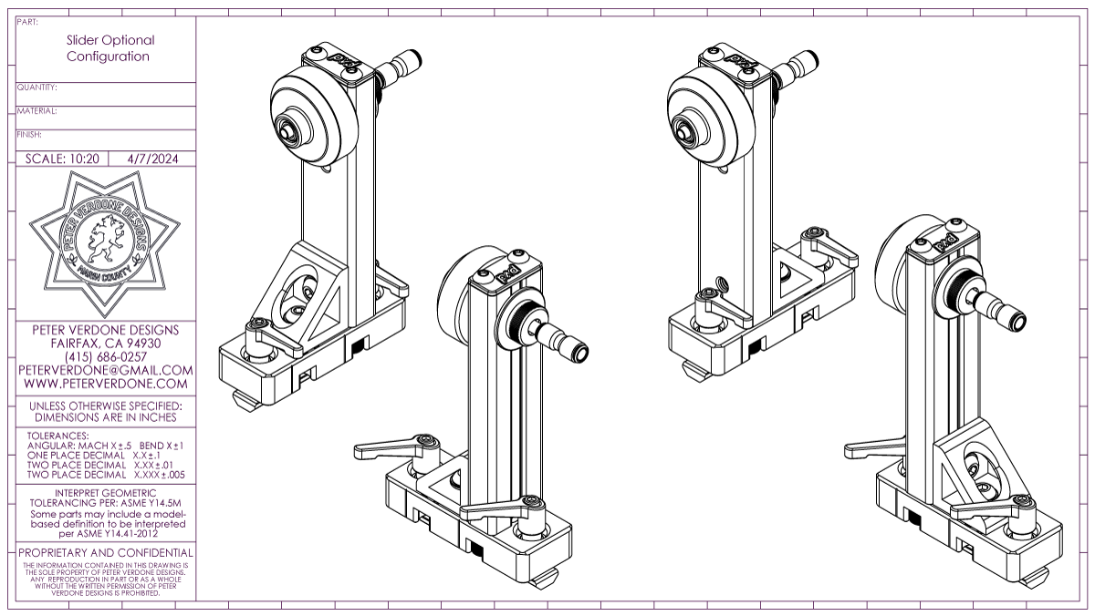
Cone slides sometimes need to come close to each other, like in my 85mm head tubes. For that reason the pillar can be mounted in an optional location. This keeps a solid framework but gives space to work.
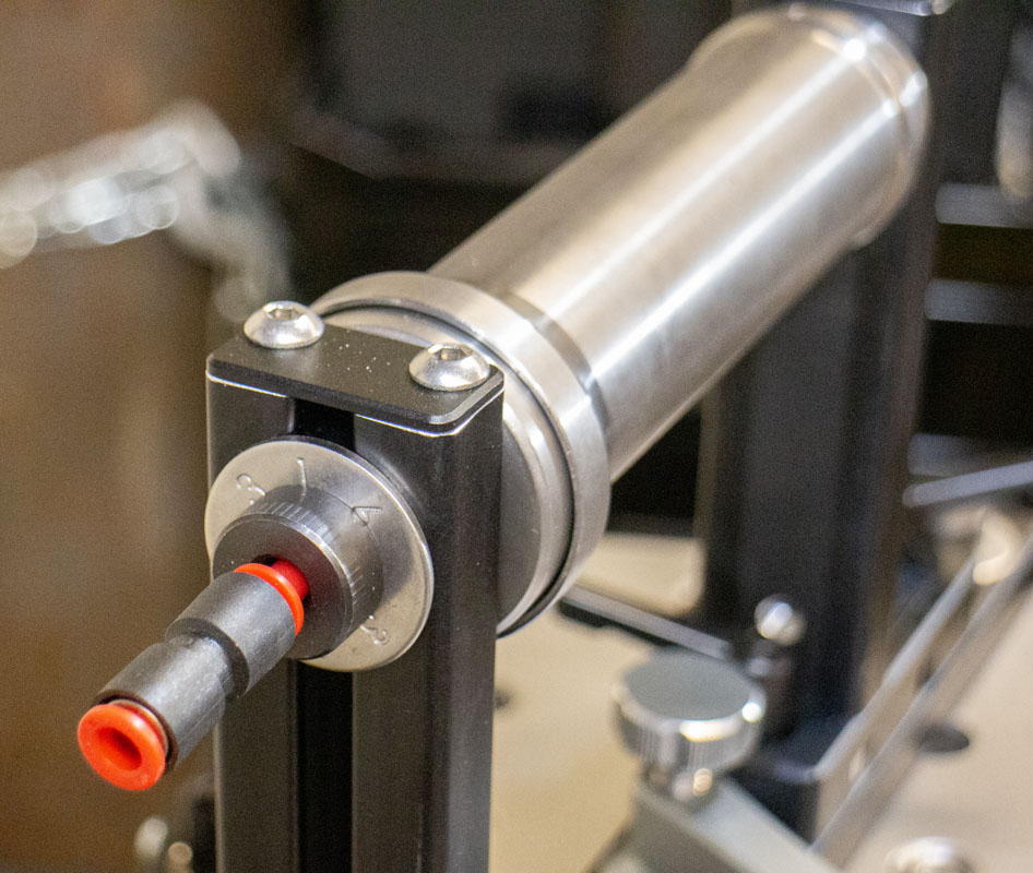
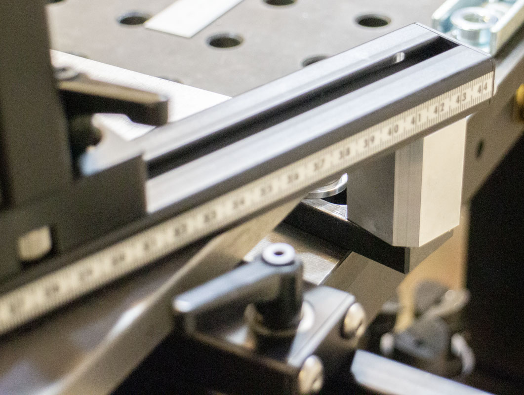
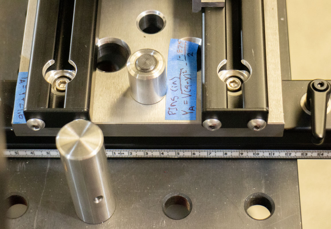
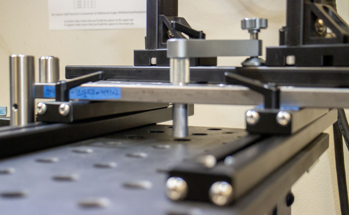
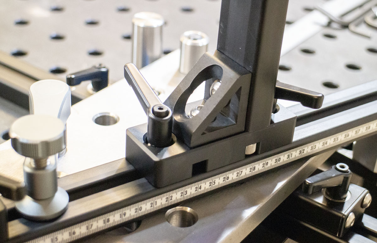
The Cyberdyne System used a 10.63″ (270mm) cosine bar to set the angles of the head and seat tube. The Samantha brings that up to 14.0″ (356mm). That’s a 32% increase in usable resolution. For example, the difference between a 70.00° (91.5mm) and 70.10° (90.9mm) beam setting is 0.6mm (0.024″). Basically, it’s easier to be more precise. Far more than any other fixture….ever?
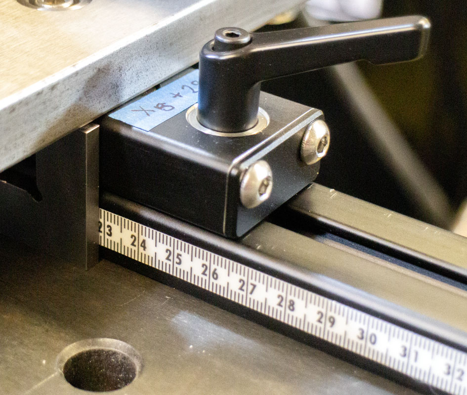
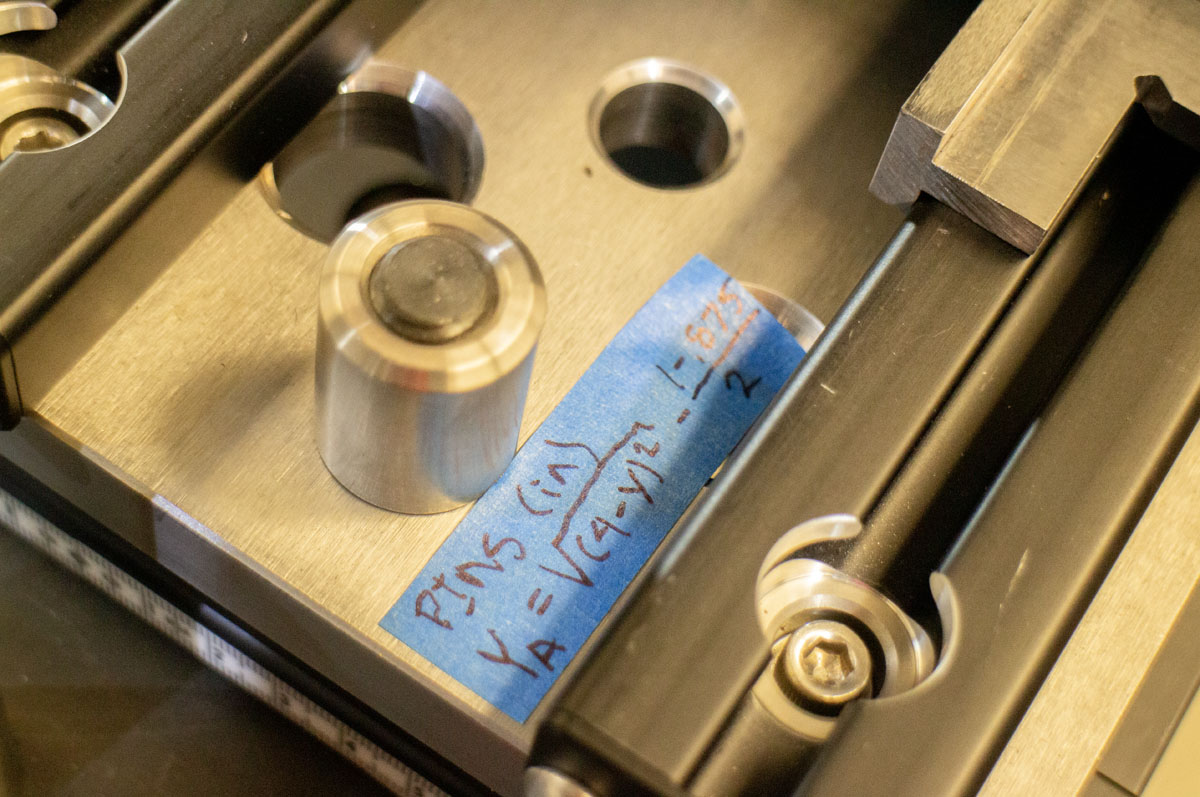
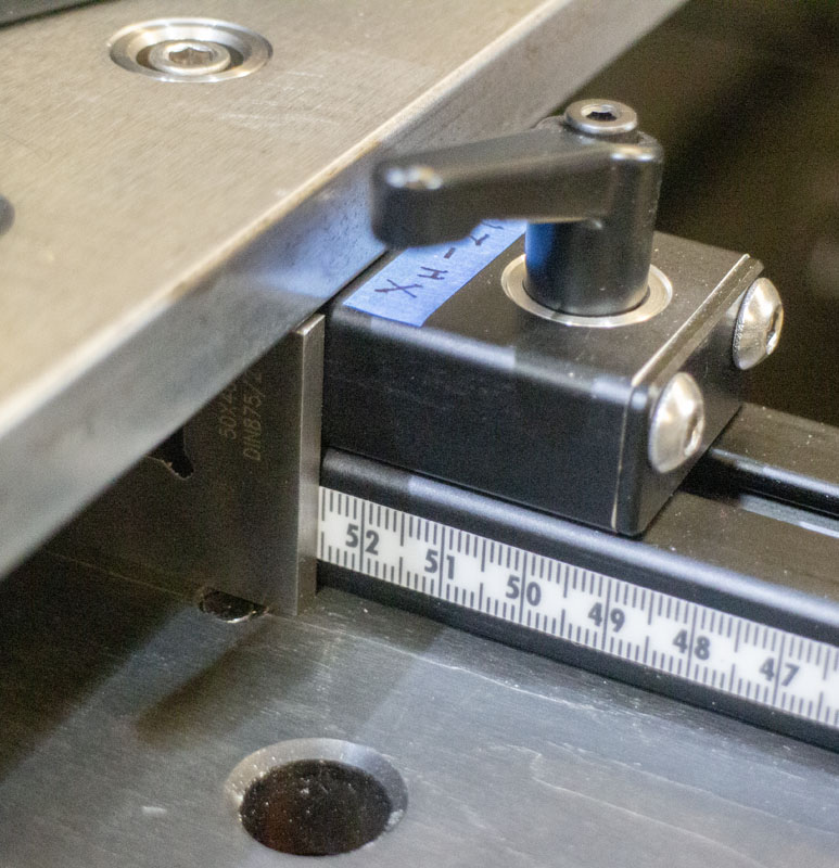
The cosine pin also acts as a point to measure to the raster from. Displacement between pins plus/minus the average of the pin diameters tell us a lot. This makes it easy to set the beams to within just a few thousands of an inch. This works for both for the X-axis location for the various parts but also the Y-axis of the rear axle slide. This is solved by simply taking SQRT((measurement between pins+(⌀pin1 +⌀pin2)/2)^2-Xaxis distance between pin centers^2). Of course, the quality of this particular measurement will be improved by maximizing the Y-axis displacement and minimizing the X-axis displacement. Very cool stuff.
I had some cheap vinyl adhesive scales left over from past projects that were stuck on the rails. Most were the 3/8″ tall scales but a small section is 1/4″. I would prefer some steel adhesive backed scales but that will wait on that for now. I’m thinking that the pin measurement system will work well for precision placement.
Quality precision is gained in another basic philosophical way. Because the pivot location for the beams are located closer in space to where the hand grips and saddle will be placed, those points will be ensured quite trivially within the context of the bike. All of this took work and deep thinking. The goal is making it easy to be more precise.
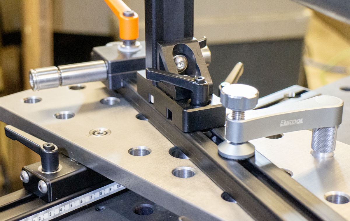
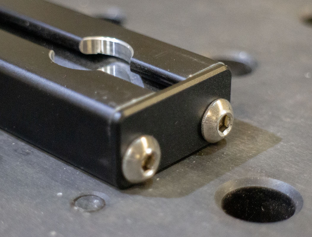
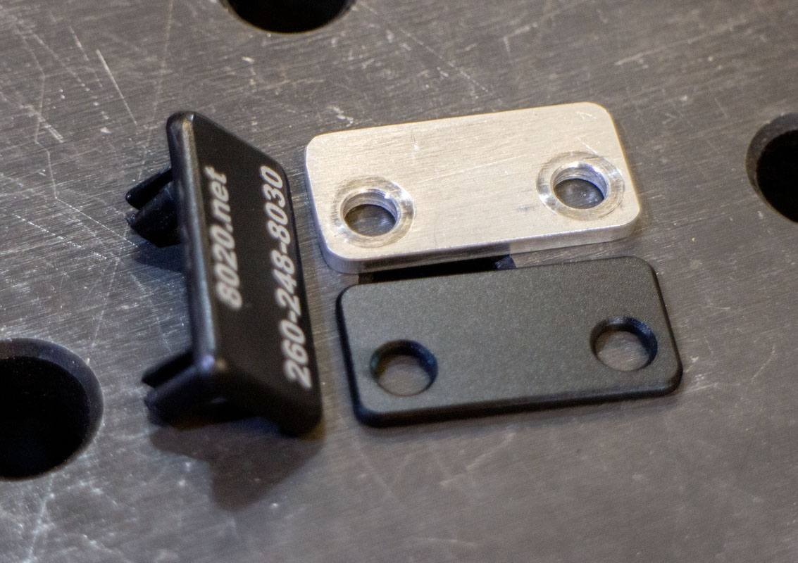
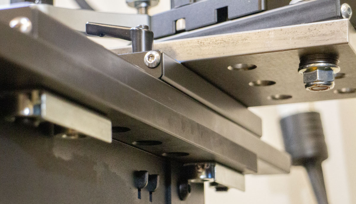
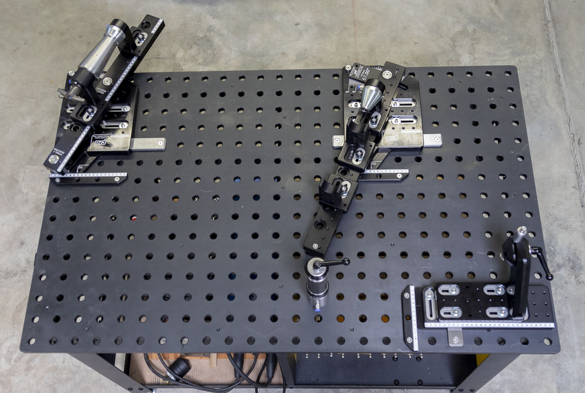
A nice detail that I made sure to add was the black anodized aluminum end plates for the 1575 8020 extrusion. It’s a shame that 8020 doesn’t sell these as their plastic end caps are effectively trash. The custom plates clean up the look of the fixture components but also add an important function: preventing the carriages from running off the end of the rails when working around or moving the assemblies. I had prototyped this when I did the wheel tool as I needed to stop the slide from separating from itself. Now I have nice ones.
I mention in one of the videos about the issue with downloaded CAD models of the adjustable levers that I use not accurately reflecting the parts. Be sure to measure your levers as they exist in fact to protect your designs. I’ve warned you.
The only detail that I’m not especially psyched about (so far) are the seat tube supports. I’m missing something in the construction or design but don’t have the time for a deep dive right now. I may change the design to have a modular top piece for differing tube diameters. Anyway, you may see an update on that in the future.
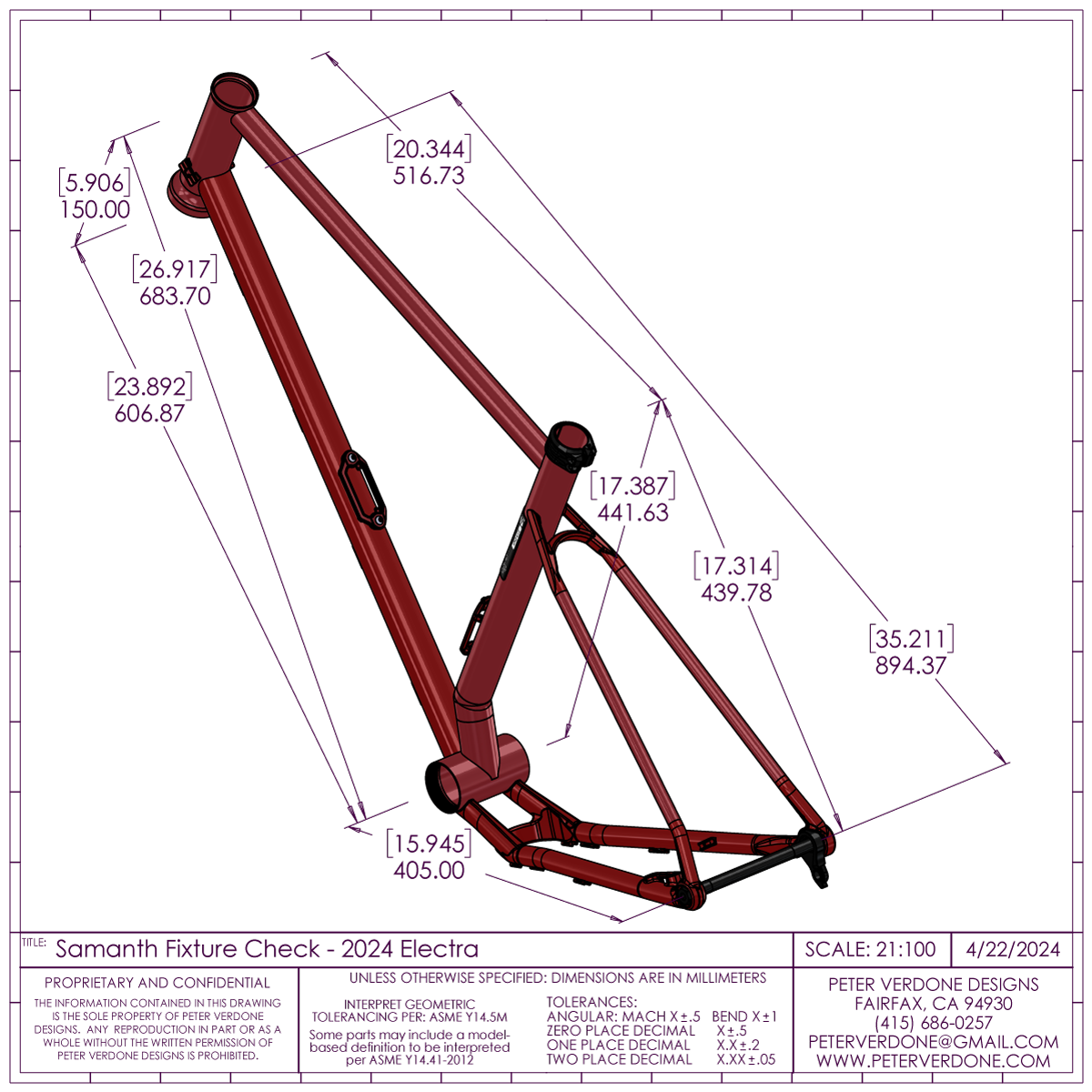
Below is an example of the calculations that are performed for setting the fixture. As always, we enter driving parameters from the chassis design producing very precise locations for the components. Notice that a new parameter has been included for fork slider angle from steerer to work with newer all-road suspension forks. Note that this is not a design environment, it’s a calculator. Your driving parameters would be coming from a sorted design.
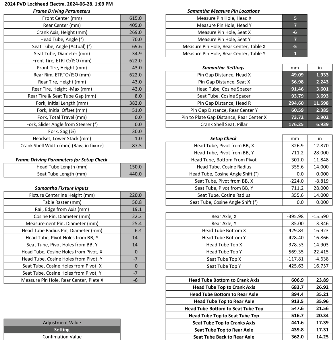
Setting and adjusting the fixture is really wonderful. The pin system along with the slide means I can count on precision. Setting this fixture with calipers to a thousandths of an inch is something that I’ve wanted for a pair of decades. I still have to do the proper final calibration but measures are already working well.
I’ve produced a documentation package for the Samantha fixture. I’m not sure where that is going but it exists. Should I release the plans? Should I make a kit to sell? It’s hard to know the next setup for a design but for now, I have a very nice tool.
An old video from a very early state of the design, circa December 8, 2023